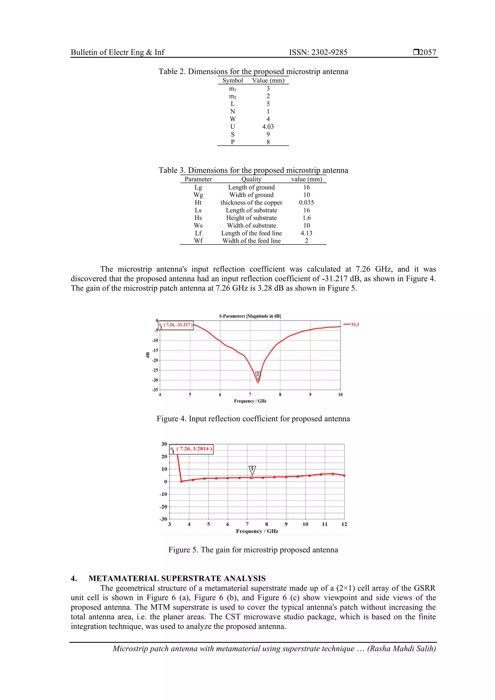
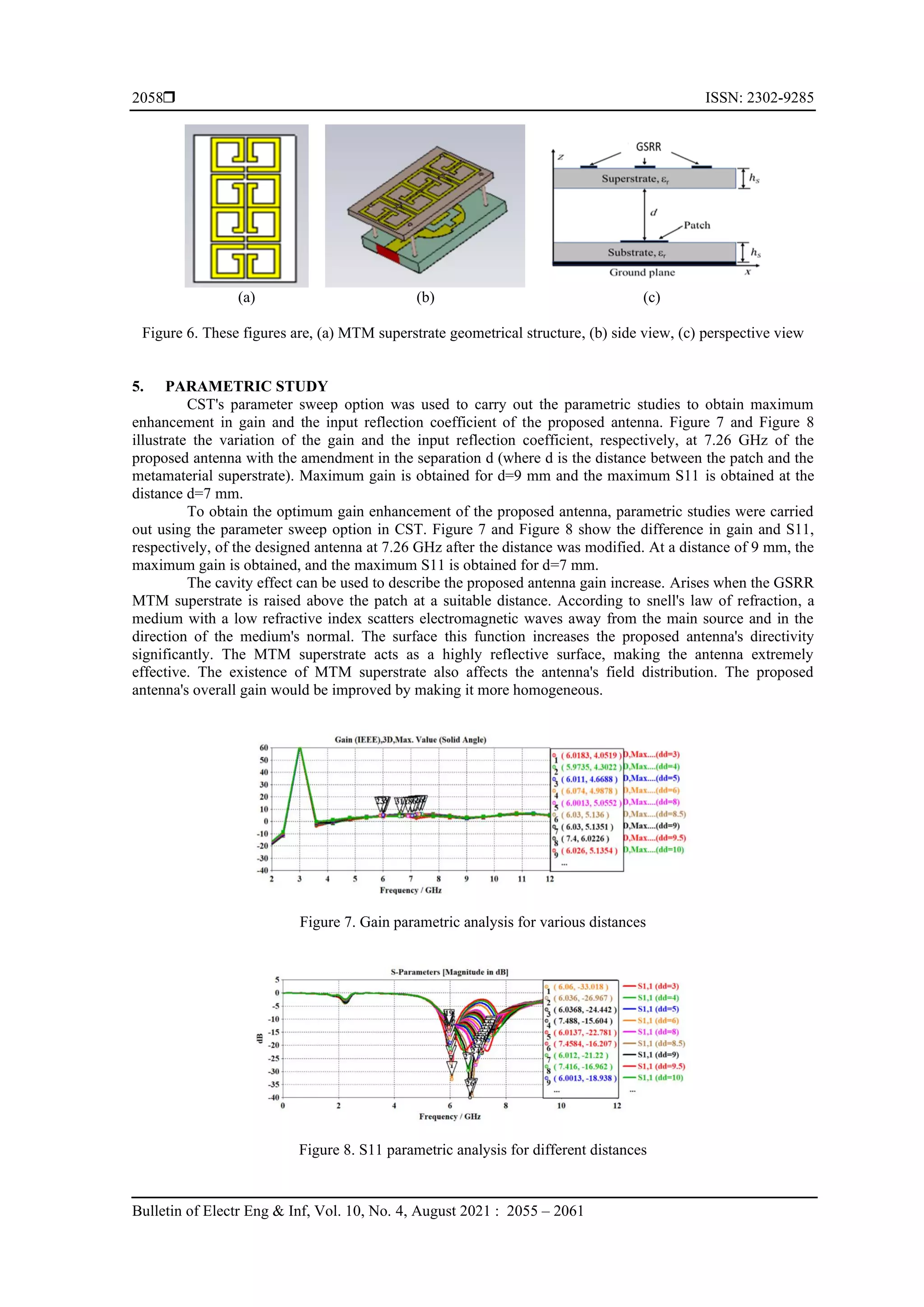
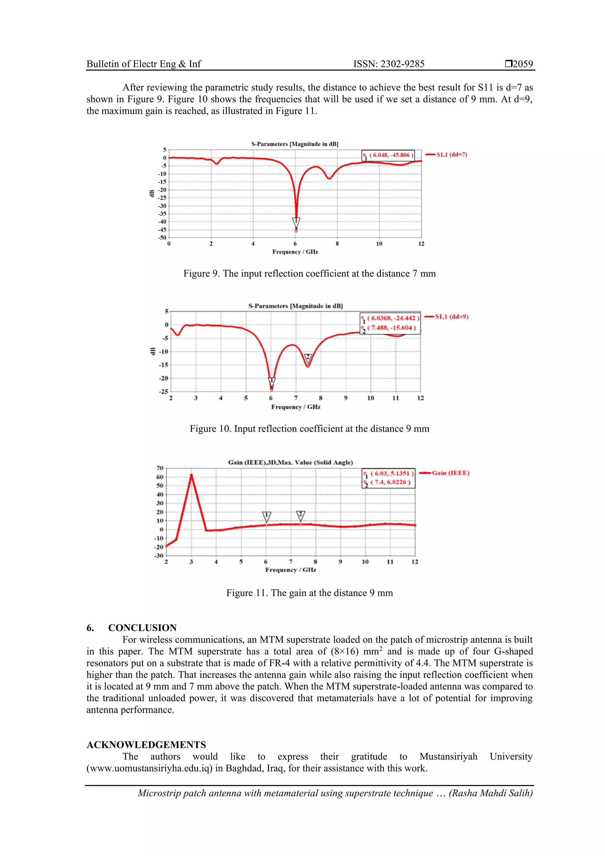
This document presents a study on a metamaterial superstrate applied to a microstrip patch antenna aimed at enhancing performance for wireless communications. The superstrate, consisting of four G-shaped resonators, significantly improves the antenna's gain from 3.28 dB to 6.02 dB and the input reflection coefficient from -31.217 dB to -45.8 dB when positioned optimally above the patch. The research demonstrates the potential of metamaterials in improving antenna efficiency and effectiveness.
![Bulletin of Electrical Engineering and Informatics
Vol. 10, No. 4, August 2021, pp. 2055~2061
ISSN: 2302-9285, DOI: 10.11591/eei.v10i4.2722 2055
Journal homepage: http://beei.org
Microstrip patch antenna with metamaterial using superstrate
technique for wireless communication
Rasha Mahdi Salih, Ali Khalid Jassim
Electrical Engineering Department, College of Engineering, Mustansiriyah University, Baghdad, Iraq
Article Info ABSTRACT
Article history:
Received Sep 11, 2020
Revised Apr 29, 2021
Accepted May 25, 2021
This work builds a metamaterial (MTM) superstrate loaded on a patch of
microstrip antenna for wireless communications. The MTM superstrate is
made up of four G-shaped resonators on FR-4 substrate with a relative
permittivity of 4.4 and has a total area of (8×16) mm2
, and is higher than the
patch. The MTM superstrate increases antenna gain while also raising the
input reflection coefficient. When it is 9 mm above the patch, the gain
increased from 3.28 dB to 6.02 dB, and when it is 7 mm above the patch, the
input reflection coefficient was enhanced from -31.217 dB to -45.8 dB. When
the MTM superstrate loaded antenna was compared to the traditional
unloaded antenna, it was discovered that metamaterials have a lot of potential
for improving antenna performance.
Keywords:
Input reflection coefficient
Metamaterial
Microstrip antenna
Superstrate
This is an open access article under the CC BY-SA license.
Corresponding Author:
Rasha Mahdi Salih
Department of Electrical Engineering
Mustansiriyah University
Baghdad, Iraq
Email: Asdfx7871@gmail.com
1. INTRODUCTION
The special properties of metamaterials have enticed scientists to develop highly efficient antennas
for future wireless communication [1]. No other ordinary/naturally occurring metamaterial has the property
that a metamaterial does [2]-[6]. Metamaterials are man-made structures that are engineered to have
properties that aren't found in nature. Veselago introduced the first metamaterial definition [7]-[9].
Metamaterials are made up of unit cells that are organized in a regular pattern [10]-[15]. Tiny metallic
resonators with a duration much shorter than the wavelength make up the unit cells. Different shapes are
possible for the unit cell. Metamaterial structures may be used to miniaturize a large antenna, add a second
resonance to a multiband antenna, increase the gain of a conventional antenna, increase the bandwidth of a
narrow band antenna, and add a second resonance to a multiband antenna [16]-[25]. The metamaterial's
exotic properties can be removed to achieve all of the antenna's aforementioned properties. In this study, we
propose a metamaterials unit cell to obtain resonances at 6 GHz. The unit cell is a G-shaped split ring
resonator (GSRR). The dielectric constant of the usable FR4 substrate is 4.4 and the height is 1.6 mm.
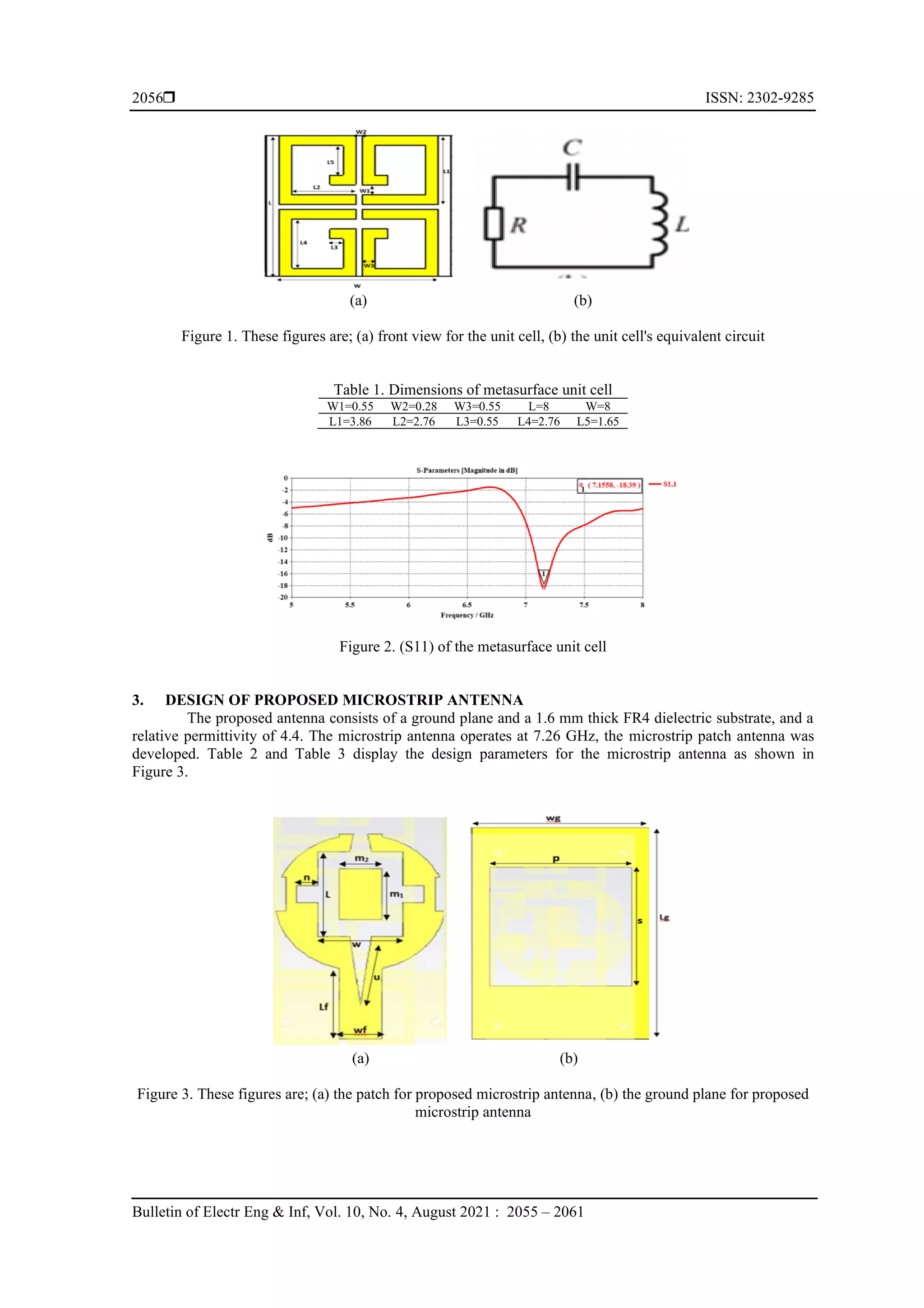
2. DESIGN OF THE METASURFACE UNIT CELL
The proposed metamaterial unit cell is made up of four symmetrically aligned GSRR. Placing the
cell in the middle determines the medium parameters. In Figure 1, the proposed GSRR's extensive dimension
layout and the electrical circuit represented it is. Table 1 shows the dimensions of the proposed metasurface
unit cell. The input reflection cofficient (S11) of the metasurface unit cell as shown in Figure 2.](https://image.slidesharecdn.com/342722-210818025427/75/Microstrip-patch-antenna-with-metamaterial-using-superstrate-technique-for-wireless-communication-1-2048.jpg)
![ ISSN: 2302-9285
Bulletin of Electr Eng & Inf, Vol. 10, No. 4, August 2021 : 2055 – 2061
2060
REFERENCES
[1] T. Ali, S. Pathan, and R. Biradar, “Frequency Reconfigurable and Metamaterial Antennas Design Techniques‐
Present and Future Research Directions,” Internet Technology Letters, vol. 1, no. 10, p. e19, 2018, doi:
10.1002/itl2019.
[2] V. G. Veselago, “The electrodynamics of substances with simultaneously negative values of and μ,” Soviet physics
uspekhi, vol. 10, no. 4, pp. 509-514, 1968.
[3] M. Lapine and S. Tretyakov,” Contemporary notes on metamaterials,” IET microwaves, antennas & propagation,
vol. 1, no. 1, pp. 3-11, 2007, doi: 10.1049/iet-map:20050307.
[4] T. Ali, M. Khaleeq, S. Pathan, and R. Biradar, “A multiband antenna loaded with metamaterial and slots for
GPS/WLAN/WiMAX applications,” Microwave and Optical Technology Letters, vol. 60, no. 1, pp. 79-85, 2018,
doi: 10.1002/mop.30921.
[5] Tanweer Ali and Rajashekhar C. Biradar, “A Miniaturized Volkswagen Logo UWB Antenna with Slotted Ground
Structure and Metamaterial for GPS,” Progress in Electromagnetics Research C, vol. 72, pp. 29-41, 2017, doi:
10.2528/PIERC16120109.
[6] Y. Dong and T. Itoh, "Metamaterial-Based Antennas," in Proceedings of the IEEE, vol. 100, no. 7, pp. 2271-2285,
July 2012, doi: 10.1109/JPROC.2012.2187631.
[7] Y. Dong, H. Toyao and T. Itoh, "Design and Characterization of Miniaturized Patch Antennas Loaded With
Complementary Split-Ring Resonators," in IEEE Transactions on Antennas and Propagation, vol. 60, no. 2, pp.
772-785, Feb. 2012, doi: 10.1109/TAP.2011.2173120.
[8] F. Raval, Y. P. Kosta, and H. Joshi, “Reduced size patch antenna using complementary split ring resonator as
defected ground plane,” AEU-International Journal of Electronics and Communications, vol. 69, no. 8, pp. 1126-
1133, 2015, doi: 10.1016/j.aeue.2015.04.013.
[9] Yang Cao, Xing Yu, Hongquan Feng, Rubing Han and Yuanyun Liu, "Waveguide demonstration of active
frequency selective surface in K-band," 2016 Progress in Electromagnetic Research Symposium (PIERS), 2016, pp.
3735-3739, doi: 10.1109/PIERS.2016.7735414.
[10] D. R. Smith, D. C. Vier, Th. Koschny, and C. M. Soukoulis, “Electromagnetic parameter retrieval from
inhomogeneous metamaterials,” Physical review E, vol. 71, no. 3, p. 036617, 2005.
[11] Z. Szabó, G. Park, R. Hedge and E. Li, "A Unique Extraction of Metamaterial Parameters Based on Kramers–
Kronig Relationship," in IEEE Transactions on Microwave Theory and Techniques, vol. 58, no. 10, pp. 2646-2653,
Oct. 2010, doi: 10.1109/TMTT.2010.2065310.
[12] A. A. Jabber, A. K. Jassim, and R. H. Thaher, “Compact reconfigurable PIFA antenna for wireless applications,”
Telkomnika, vol. 18, no. 2, pp. 595–602, 2020, doi: 10.12928/telkomnika.v18i2.13427.
[13] Z. Szabó, G. Park, R. Hedge and E. Li, "A Unique Extraction of Metamaterial Parameters Based on Kramers–
Kronig Relationship," in IEEE Transactions on Microwave Theory and Techniques, vol. 58, no. 10, pp. 2646-2653,
Oct. 2010, doi: 10.1109/TMTT.2010.2065310.
[14] A. Benedetti, C. Sibilia, and M. Bertolotti, “Wideband negative magnetic permeability materials (NMPM) with
composite metal-semiconductor structures based on the Drude model, and applications to negative-refractive index
(NIM),” Optics Express, vol. 15, no. 11, pp. 6534-6545, 2007, doi: 10.1364/OE.15.006534.
[15] J. B. Pendry, A. J. Holden, D. J. Robbins, and W. J. Stewart, “Low-frequency plasmons in thin-wire structures,”
Journal of Physics: Condensed Matter, vol. 10, no. 22, p. 4785, 1998, doi: 10.1088/0953-8984/10/22/007.
[16] J. B. Pendry, A. J. Holden, W. J. Stewart, and I. Youngs, “Extremely low-frequency plasmons in metallic
mesostructures,” Physical review letters, vol. 76, no. 25, p. 4773, 1996, doi: 10.1103/PhysRevLett.76.4773.
[17] A. Alu and N. Engheta, "Pairing an epsilon-negative slab with a mu-negative slab: resonance, tunneling and
transparency," in IEEE Transactions on Antennas and Propagation, vol. 51, no. 10, pp. 2558-2571, Oct. 2003, doi:
10.1109/TAP.2003.817553.
[18] D. R. Smith, D. C. Vier, T. Koschny, and C. M. Soukoulis, “Electromagnetic parameter retrieval from
inhomogeneous metamaterials,” Physical review E, vol. 71, no. 3, p. 36617, 2005, doi:
10.1103/PhysRevE.71.036617.
[19] A. K. Jassim, M. Jasim, A. F. Fahad, “Design selective band antenna using coupling sidewall and multi resonator
for wireless communications,” Bulletin of Electrical Engineering and Informatics, vol. 9, no. 5, pp. 2206-2212,
2020, doi: 10.11591/eei.v9i5.2247.
[20] J. Baker-Jarvis, E. J. Vanzura and W. A. Kissick, "Improved technique for determining complex permittivity with
the transmission/reflection method," in IEEE Transactions on Microwave Theory and Techniques, vol. 38, no. 8,
pp. 1096-1103, Aug. 1990, doi: 10.1109/22.57336.
[21] X. Chen, T. M. Grzegorczyk, B.-I. Wu, J. Pacheco Jr, and J. A. Kong, “Robust method to retrieve the constitutive
effective parameters of metamaterials,” Physical review E, vol. 70, no. 1, p. 16608, 2004, doi:
10.1103/PHYSREVE.70.016608.
[22] H. A. Majid, M. K. A. Rahim and T. Masri, "Left handed metamaterial design for microstrip antenna application,"
2008 IEEE International RF and Microwave Conference, 2008, pp. 218-221, doi: 10.1109/RFM.2008.4897426.
[23] G. Kiziltas and J. L. Volakis, “Miniature antenna designs on metamaterial substrates,” in 3rd European Workshop
on Conformal Antennas, (Invited Paper), Bonn, Germany, 2003.
[24] Y. Dong and T. Itoh, "Metamaterial-Based Antennas," in Proceedings of the IEEE, vol. 100, no. 7, pp. 2271-2285,
July 2012, doi: 10.1109/JPROC.2012.2187631.](https://image.slidesharecdn.com/342722-210818025427/75/Microstrip-patch-antenna-with-metamaterial-using-superstrate-technique-for-wireless-communication-6-2048.jpg)
![Bulletin of Electr Eng & Inf ISSN: 2302-9285
Microstrip patch antenna with metamaterial using superstrate technique … (Rasha Mahdi Salih)
2061
[25] Ali Khalid Jassim and R. H. Thaher, “Design and analysis microstrip antenna with a reflector to enhancement gain
for wireless communication,” Bulletin of Electrical Engineering and Informatics, vol. 9, no. 2, pp. 652-660, 2020,
doi: 10.11591/eei.v9i2.1696.
[26] K. Aydin and E. Ozbay, “Left-handed metamaterial-based superlens for subwavelength imaging of electromagnetic
waves,” Applied Physics A, vol. 87, no. 2, pp. 137-141, 2007, doi: 10.1007/s00339-006-3817-4.
BIOGRAPHIES OF AUTHORS
Rasha Mahdi Salih: received the B.S. E. E. degrees in electrical engineering from
Mustansiriyh University, Baghdad, Iraq, in 2008. Her current research interest, in the areas of
microstrip antennas with metasurface for a master's degree. E-mail: asdfx7871@gmail.com
Asst. Prof. Dr. Ali Khalid Jassim: at Mustansiriyah University, college Engineering of
Electrical Engineering Department. Holds a Bachelor's degree in 1999 and a Master’s degree
in 2010 and a Ph.D. in 2019 in communications engineering. Works in the field of cellular
networks communications and antennas and has a many of research in international journals
and scientific conferences. E-mail: alijassim79@yahoo.com,
alijassim@uomustansiriyah.edu.iq](https://image.slidesharecdn.com/342722-210818025427/75/Microstrip-patch-antenna-with-metamaterial-using-superstrate-technique-for-wireless-communication-7-2048.jpg)