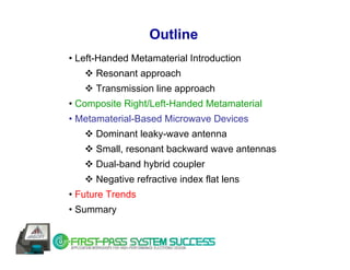
Download as PDF, PPTX


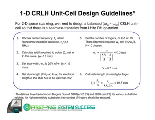
![Rectangular Waveguide Filled with LHM
→
Pin k backward wave (vp = -vg)
ε>0, μ>0 →
k
→
→ ε<0, μ<0
k
S
LH Triad ε>0, μ>0
→
S
Pout
→
S
HFSS simulation using effective medium [1]
naturally occurring LH material has not yet been discovered](https://image.slidesharecdn.com/metamateriales-100502230511-phpapp01/85/Metamateriales-5-320.jpg)
![LHM – Resonant Approach
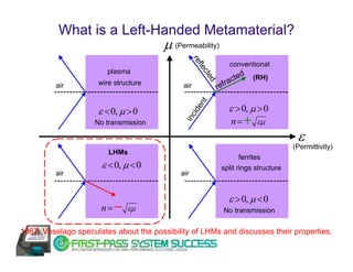
• 1967: LHM were first proposed by Russian Physicist Victor Veselago
• 2001: LHM realized based on split ring resonators - Resonant Approach towards LHMs [2].
SRR
metal wire
SRR-based LHM unit-cell
SRR: at resonance provides μ<0
metal wire: provides ε<0
• SRR-based metamaterials only exhibit LH properties at resonance - inherently narrow-band
and lossy.
• SRR-based LHMs are bulky - not practical for microwave engineering applications.](https://image.slidesharecdn.com/metamateriales-100502230511-phpapp01/85/Metamateriales-6-320.jpg)
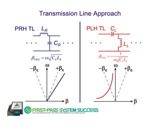
![LHM – Transmission Line Approach
• Backward wave transmission line can form a non-resonant LHM [3]-[4].
• Transmission Line Approach is based on the dual of a conventional transmission line.
Series capacitance (CL) and shunt
CL CL CL inductance (LL) combination
supports a fundamental backward
wave.
LL LL −1
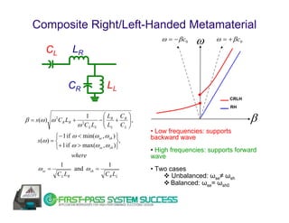
β=
Perfect LH transmission line ω C L LL
• Perfect LH transmission line not resonant dependent - low-loss and broad-band performance.
• However, perfect LH transmission line is not possible due to unavoidable parasitic right-
handed (RH) effects occurring with physical realization.](https://image.slidesharecdn.com/metamateriales-100502230511-phpapp01/85/Metamateriales-7-320.jpg)
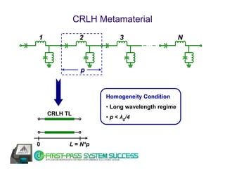
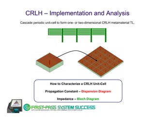
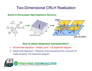
![CRLH Metamaterial – Physical Realization
CL LR capacitors
metal pads
(provides RH effects)
CR LL inductor
via to gnd
Composite right/left-handed (CRLH) unit-cell Lumped element implementation
Distributed microstrip implementation Distributed microstrip implementation based
based on interdigital capacitor on Sievenpiper mushroom structure [5]](https://image.slidesharecdn.com/metamateriales-100502230511-phpapp01/85/Metamateriales-11-320.jpg)
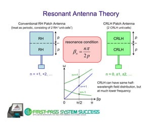
![Leaky-Wave Antenna Theory
Principle
Conventional RH Leaky-Wave Antenna z ko
(operated at higher-order mode)
kz
θ
β
source x
θ = asin(β (ω ) k0 )
CRLH Leaky-Wave Antenna [6]
(operated at dominant mode) kz2= ko2- β2
ω = − β c0 ω ω = + β c0
Characteristics:
II III
LH RH • Operating in leaky regions
RAD. RAD.
II : BACKWARD ( β < 0 )
CRLH
I IV RH
III : FORWARD ( β > 0 )
LH RH
GUIDANCE GUIDANCE • BROADSIDE radiation ( β = 0 )
ω0
balanced case: vg(β = 0 ) ≠ 0
β • Fundamental mode](https://image.slidesharecdn.com/metamateriales-100502230511-phpapp01/85/Metamateriales-15-320.jpg)
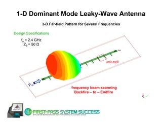
![1.0 GHz CRLH n=-1 Antenna [7]
for 4 unit-cells
5
Initial dispersion curve
4 Increase LL
Frequency (GHz)
Increase CL
3 Increase CL & LL
2
1
0
0 0.25 0.5 0.75 1
β∗ρ/π n= -1 mode is used
h1 = 3.16 mm
MIM 12.2 mm h2 = 0.254 mm
Capacitance z y
15 mm
x
CPW stub
h2
h1
1/19λ0 x 1/23λ0 x 1/88λ0
ground CWP feed](https://image.slidesharecdn.com/metamateriales-100502230511-phpapp01/85/Metamateriales-28-320.jpg)
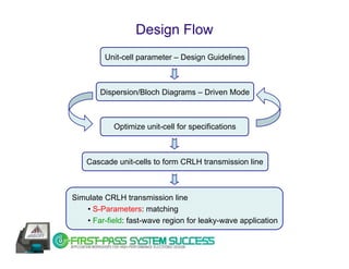
![1.0 GHz CRLH n=-1 Antenna [7]
0
-5
n = -3 top view
Return Loss (dB)
-10 n = -2
-15
-20
n = -1
measurement HFSS
-25
0 0.5 1 1.5 2 2.5 3 3.5 4 4.5 5
Frequency (GHz)
E-copol (x-z plane) H-copol (y-z plane) back view
E-xpol (x-z plane) H-xpol (y-z plane)
90 90
-5 -5
-10
135 -15
45 135 -10 45
-20 -15
-25 -20
-30 -25
-35
-30
-40
-45 -35
-50 -40 -35 -30 -25 -20 -15 -10 -5
-45 -40-35 -30 -25 -20 -15 -10 -5
180 0 180 0
225 315 225 315
270 270](https://image.slidesharecdn.com/metamateriales-100502230511-phpapp01/85/Metamateriales-29-320.jpg)
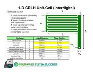
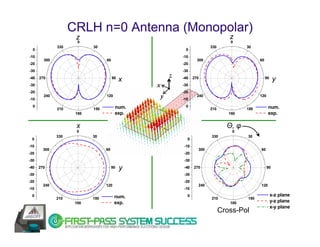
![CRLH n=0 Antenna (Monopolar) [8]
Experimental Results
6 4.0
3.8
Frequency (GHz)
Peak Gain (dBi)
4
3.6
3.4
2
ω
3.2
ω = − β c0 ω = + β c0 Exp. Peak Gain
Exp. Resonant Frequency
0 3.0
2 4 6
# of unit-cells (N)
n=0 points
As N increases…
CRLH • Gain increases.
RH
• Resonant frequency does not
β change much.](https://image.slidesharecdn.com/metamateriales-100502230511-phpapp01/85/Metamateriales-30-320.jpg)
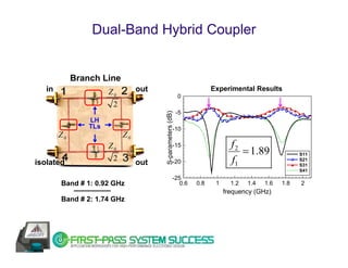
![Dual-Band Hybrid Coupler
CRLH / CRLH hybrid [9]
360
1 CRLH 2 Conventional quadrature:
270 restricted to odd harmonics
because only control on slope
CRLH CRLH
180
4 CRLH 3 DC offset
90
Characteristics: f0 f1 f 2CRLH f 2conv = 3 f1
0 f
• dual-band functionality for an
arbitrary pair of frequencies f1, f2 −90
• principle: transition frequency (fo)
−180
provides DC offset additional degree
of freedom with respect to the
−270 conv. RH
phase slope CRLH
• applications in multi-band systems −360](https://image.slidesharecdn.com/metamateriales-100502230511-phpapp01/85/Metamateriales-33-320.jpg)
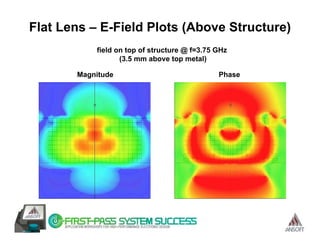
![Negative Refractive Index Flat Lens [10]
(nLH)sinθLH = (nRH) sinθRH Effective medium HFSS simulation
RHM
source
(15 mm from interface)
LHM
θRH θLH
RH medium LH medium
refractive index nRH > 0 refractive index nLH < 0
Possibility of realizing a flat lens
E-field magnitude
RH medium RH medium 1
LH medium RH medium 2](https://image.slidesharecdn.com/metamateriales-100502230511-phpapp01/85/Metamateriales-36-320.jpg)
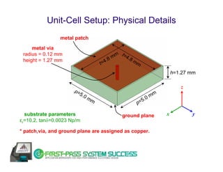
![Sievenpiper Unit-Cell: 1st Order Calculation
distributed unit-cell equivalent circuit model
fsh = 1/{2πsqrt(CR x LL)}
series capacitance: CR ~ substrate permittivity x (patch area/substrate height)
shunt inductance: LL ~ 0.2 x substrate height x ln[(2 x substrate height/via radis) – 1]
* Left-handed mode will always occur below the shunt resonance (ωsh). Therefore,
design dimensions such that wsh occurs at higher limit of frequency of interest.
fsh ~ 5 GHz for the dimensions shown in previous slide.](https://image.slidesharecdn.com/metamateriales-100502230511-phpapp01/85/Metamateriales-40-320.jpg)


![Applications & Research
Metamaterial Multiple-Input-Multiple-Output (MIMO)
Arrays for 802.11n Application [11]
Active CRLH Metamaterials
• High-gain leaky-wave antennas (embed amplifiers in unit-cell) [12]
• Distributed amplifiers [13]
Tunable Phase Shifters [14]](https://image.slidesharecdn.com/metamateriales-100502230511-phpapp01/85/Metamateriales-56-320.jpg)
![Implementations
Nano-Metamaterials: optical frequency applications [15]
Evanescent-Mode Metamaterials [16]
1-D LHM: cylindrical DRs in TE mode cutoff
parallel plate waveguide (-ε)
H-field Profile (TE01δ mode, -μ)
Three-Dimensional Metamaterials [17]](https://image.slidesharecdn.com/metamateriales-100502230511-phpapp01/85/Metamateriales-57-320.jpg)


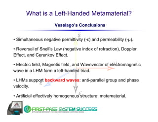
The document discusses left-handed metamaterials (LHMs) and their applications in microwave engineering. It introduces LHMs, including their defining properties of simultaneous negative permeability and permittivity. It describes two approaches to realizing LHMs - a resonant approach using split-ring resonators and a non-resonant transmission line approach. It then discusses composite right/left-handed metamaterials and their implementation using lumped element unit cells. Finally, it provides examples of metamaterial-based microwave devices like leaky-wave antennas that take advantage of the unique properties of LHMs.


