Downloaded 265 times
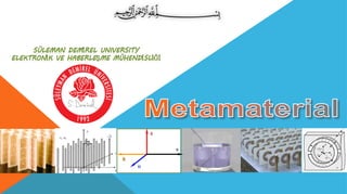


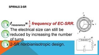
![METAMATERIAL BACKGROUND
Do not depend on the chemical
composition
Depend on the geometry of the
structure units. [1]
Metamaterials are artificial
engineered composite structures.
Not commonly found in nature.[2]](https://image.slidesharecdn.com/5c9kc8htteiuwww1vjul-signature-53e2e80f8da1b932ebd9306489c2a7c00956ce2524aee1f539cc3830a0b1526e-poli-150522211810-lva1-app6892/85/Metamaterial-4-320.jpg)
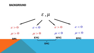
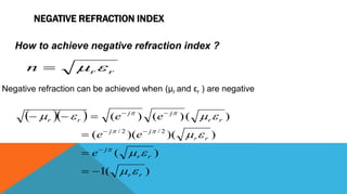
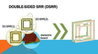
![NEGATIVE REFRACTION INDEX
Fig. 1. (a) Calculated ray-tracing image of a metal rod in an empty drinking glass. (b) Same
scenery, but the glass is filled with normal water, n 1.3 , leading to ordinary refraction. (c)
The water is replaced by “water” with a fictitious refractive index of n 1.3 .[5]
*Gunnar Dolling and Martin Wegener :Photorealistic images of objects in effective negative-index materials, 6 March 2006 / Vol. 14, No. 5 / OPTICS EXPRESS 1843](https://image.slidesharecdn.com/5c9kc8htteiuwww1vjul-signature-53e2e80f8da1b932ebd9306489c2a7c00956ce2524aee1f539cc3830a0b1526e-poli-150522211810-lva1-app6892/85/Metamaterial-10-320.jpg)
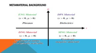
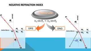
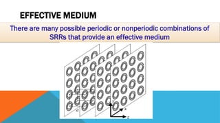
![SWISS ROLL
Anisotropic metamaterial.[3]
It is well suited to operation in (RF) range, because it has a
low resonant frequency and a strong magnetic response.[4]
Example: Swiss Roll
material operating at
21.5 MHz for which
λ/a > 1000 (where a
is the unit cell size).](https://image.slidesharecdn.com/5c9kc8htteiuwww1vjul-signature-53e2e80f8da1b932ebd9306489c2a7c00956ce2524aee1f539cc3830a0b1526e-poli-150522211810-lva1-app6892/85/Metamaterial-29-320.jpg)
![REFERENCES
[1] Tatjana Asenov,Nebojša Dončovm ,Bratislav Milovanović: Application of Metamaterials for the Microwave Antenna
Realisations, SERBIAN JOURNAL OF ELECTRICAL ENGINEERING Vol. 9, No. 1, February 2012, 1-7
[2] MARQUES, RICARDO , FERRAN MARTIN and MARIO SOROLLA. Metamaterials with Negative Parameters:
Theory, Design, and Microwave Applications. John Wiley & Sons, Inc., 2008.
[3] M. C. K. Wiltshire and J. V. Hajnal, Metamaterial endoscope for magnetic field transfer: near field imaging with
magnetic wires, 2003 OSA 7 April 2003 / Vol. 11, No. 7 / OPTICS EXPRESS 713
[4] M C Kwiltshire, J B Pendry, An effective medium description of 'Swiss Rolls', a magnetic metamaterial, IOP
PUBLISHING JOURNAL OF PHYSICS: CONDENSED MATTER, 19 (2007) 456216 (16pp)
[5] Gunnar Dolling and Martin Wegener :Photorealistic images of objects in effective negative-index materials, 6 March
2006 / Vol. 14, No. 5 / OPTICS EXPRESS 1843
[6] A. Ishimaru, S. Jaruwatanadilok, and Y. Kuga by there research ( GENERALIZED SURFACE PLASMON
RESONANCE SENSORS USING METAMATERIALS AND NEGATIVE INDEX MATERIALS) Progress In
Electromagnetics Research, PIER 51, 139–152, 2005](https://image.slidesharecdn.com/5c9kc8htteiuwww1vjul-signature-53e2e80f8da1b932ebd9306489c2a7c00956ce2524aee1f539cc3830a0b1526e-poli-150522211810-lva1-app6892/85/Metamaterial-34-320.jpg)


The document discusses metamaterials, which are engineered composite structures whose properties depend on geometry rather than chemical composition. It covers topics such as negative refraction index, designs of split ring resonators (SRRs), and various configurations that influence electromagnetic behavior. Additionally, it references several studies and applications related to metamaterials within the microwave and RF ranges.