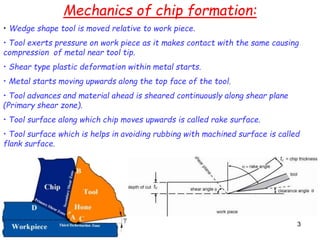
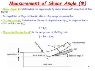
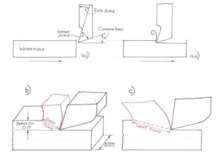
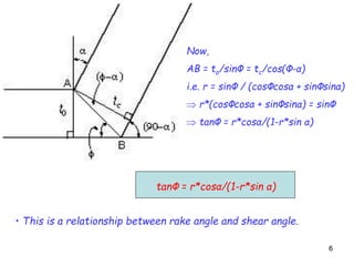
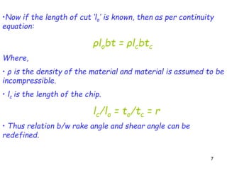
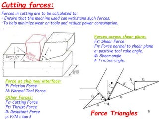
11
Topic – Analysis of Cutting forces in Orthogonal metal
cutting(2D cutting) with the help of Merchants Circle
by
Mr. Binit kumar
Assistant Prof., ME department
GLBITM, Greater Noida
2
Introduction
• Object of mfg process is to produce piece of specified shape.
• Any of the following three type of operations may be employed for the same:
1. Constant Mass Operation (Casting, rolling etc.)
2. Material Addition Operation (Welding, Bolting, riveting etc)
3. Material Removal Operation (Machining, grinding, lapping etc)
33
Mechanics of chip formation:
• Wedge shape tool is moved relative to work piece.
• Tool exerts pressure on work piece as it makes contact with the same causing
compression of metal near tool tip.
• Shear type plastic deformation within metal starts.
• Metal starts moving upwards along the top face of the tool.
• Tool advances and material ahead is sheared continuously along shear plane
(Primary shear zone).
• Tool surface along which chip moves upwards is called rake surface.
• Tool surface which is helps in avoiding rubbing with machined surface is called
flank surface.
44
Measurement of Shear Angle (Φ)
• Shear Angle Φis defined as the angle made by shear plane with direction of tool
travel.
• Cutting Ratio or Chip thickness ratio or chip compression factor:
• Cutting ratio (r) is defined as the uncut chip thickness (t0) to chip thickness
after metal is cut (tc).
r = t0/tc
• Chip reduction factor (ζ) is the reciprocal of Cutting ratio.
ζ = 1/r = tc/t0
A
B
55
66
tanΦ = r*cosα/(1-r*sin α)
Now,
AB = to/sinΦ = tc/cos(Φ-α)
i.e. r = sinΦ / (cosΦcosα + sinΦsinα)
 r*(cosΦcosα + sinΦsinα) = sinΦ
 tanΦ = r*cosα/(1-r*sin α)
• This is a relationship between rake angle and shear angle.
77
•Now if the length of cut ‘lo’ is known, then as per continuity
equation:
ρlobt = ρlcbtc
Where,
• ρ is the density of the material and material is assumed to be
incompressible.
• lc is the length of the chip.
lc/lo = to/tc = r
• Thus relation b/w rake angle and shear angle can be
redefined.
88
Cutting forces:
Forces in cutting are to be calculated to:
• Ensure that the machine used can withstand such forces.
•To help minimize wear on tools and reduce power consumption.
Forces across shear plane:
Fs: Shear Force
Fn: Force normal to shear plane
α: positive tool rake angle.
Φ: Shear angle
λ: Friction angle.
Force at chip tool interface:
F: Friction Force
N: Normal Tool Force
Other Forces:
Fc: Cutting Force
Ft: Thrust Force
R: Resultant Force
μ: F/N = tan λ
Force Triangles
99
• Shear Force ‘Fs’ is resistance to shear of metal.
• Normal Force ‘Fn’ is the force that w/p provides for backing up.
• Fs and Fn are at right angle to each other.
• R’ is the resultant of Fs and Fn and equal and opposite to R which is the resultant
of F and N. Thus R’ and R can be used interchangeably.
• Normal Tool Force ‘N’ acts at tool chip interface and is provided by the tool.
• Frictional Force ‘F’ is the frictional resistance of the tool acting on chip.
• All these forces can be represented with a circle called Merchant Force Circle.
• On this circle force triangles are superimposed.
• R or R’ forms the diameter of this circle.
Merchant Force Circle
• Orthogonal components of R, cutting
force Fc (horizontal) and thrust force Ft
(vertical) can be measure with the help of
dynamometer.
• Power consumed during cutting ‘E’ is:
E = Fc*V
• Where V is cutting speed.
• Now:
VV
F = Fc*Sinα + Ft*Cosα
N = Fc*Cosα – Ft*Sinα
And
Fs = Fc*CosΦ – Ft*SinΦ
Fn = Fc*SinΦ + Ft*CosΦ
V
1010
Now,
Shear Plane Area ‘As’ is
As = bto/sinΦ
And average stresses on shear plane area are:
Τs = Fs/As
σs = Fn/As
Also from Merchant Force Circle:
Also;
R = Fc*sec(λ-α)
Thus, Fs = Fc*sec(λ-α)*Cos(Φ+λ-α)
Since, Τs = Fs*SinΦ/bto
Thus, Τs = Fc*sec(λ-α)*Cos(Φ+λ-α)*SinΦ/bto
Now ‘α’ for a tool is constant and assuming that ‘λ’ is independent of ‘Φ’, and for
Maximum shear stress:
dΤs/dΦ = 0
Cos(Φ+λ-α)*CosΦ - Sin(Φ+λ-α)*SinΦ
Fs = R*Cos(Φ+λ-α)
and
Fc = R*Cos(λ-α)
11
Now,
Cutting Power Pc:
Pc = Fc*V
V = ΠDN/(1000*60) in m/s
Thus,
Pc = Fc*V/1000 in Kw
tan(Φ+λ-α) = cotΦ = tan(900-Φ)
• Thus on having high value of shear angle for a tool, value of friction angle reduces
• Thus low friction b/w tool and chip occurs and thus tool life increases and cutting
force required decreases.
Assumptions made by Merchant in making shear angle prediction:
• The work material behaves like an ideal plastic.
• The theory involves the minimum energy principle.
• As, Τs and λ are assumed to be constant and independent of Φ.
Φ = 450 + α/2 – λ/2
Thank you
12

Merchant circle cutting force anlysis

  • 1.
    11 Topic – Analysisof Cutting forces in Orthogonal metal cutting(2D cutting) with the help of Merchants Circle by Mr. Binit kumar Assistant Prof., ME department GLBITM, Greater Noida
  • 2.
    2 Introduction • Object ofmfg process is to produce piece of specified shape. • Any of the following three type of operations may be employed for the same: 1. Constant Mass Operation (Casting, rolling etc.) 2. Material Addition Operation (Welding, Bolting, riveting etc) 3. Material Removal Operation (Machining, grinding, lapping etc)
  • 3.
    33 Mechanics of chipformation: • Wedge shape tool is moved relative to work piece. • Tool exerts pressure on work piece as it makes contact with the same causing compression of metal near tool tip. • Shear type plastic deformation within metal starts. • Metal starts moving upwards along the top face of the tool. • Tool advances and material ahead is sheared continuously along shear plane (Primary shear zone). • Tool surface along which chip moves upwards is called rake surface. • Tool surface which is helps in avoiding rubbing with machined surface is called flank surface.
  • 4.
    44 Measurement of ShearAngle (Φ) • Shear Angle Φis defined as the angle made by shear plane with direction of tool travel. • Cutting Ratio or Chip thickness ratio or chip compression factor: • Cutting ratio (r) is defined as the uncut chip thickness (t0) to chip thickness after metal is cut (tc). r = t0/tc • Chip reduction factor (ζ) is the reciprocal of Cutting ratio. ζ = 1/r = tc/t0 A B
  • 5.
  • 6.
    66 tanΦ = r*cosα/(1-r*sinα) Now, AB = to/sinΦ = tc/cos(Φ-α) i.e. r = sinΦ / (cosΦcosα + sinΦsinα)  r*(cosΦcosα + sinΦsinα) = sinΦ  tanΦ = r*cosα/(1-r*sin α) • This is a relationship between rake angle and shear angle.
  • 7.
    77 •Now if thelength of cut ‘lo’ is known, then as per continuity equation: ρlobt = ρlcbtc Where, • ρ is the density of the material and material is assumed to be incompressible. • lc is the length of the chip. lc/lo = to/tc = r • Thus relation b/w rake angle and shear angle can be redefined.
  • 8.
    88 Cutting forces: Forces incutting are to be calculated to: • Ensure that the machine used can withstand such forces. •To help minimize wear on tools and reduce power consumption. Forces across shear plane: Fs: Shear Force Fn: Force normal to shear plane α: positive tool rake angle. Φ: Shear angle λ: Friction angle. Force at chip tool interface: F: Friction Force N: Normal Tool Force Other Forces: Fc: Cutting Force Ft: Thrust Force R: Resultant Force μ: F/N = tan λ Force Triangles
  • 9.
    99 • Shear Force‘Fs’ is resistance to shear of metal. • Normal Force ‘Fn’ is the force that w/p provides for backing up. • Fs and Fn are at right angle to each other. • R’ is the resultant of Fs and Fn and equal and opposite to R which is the resultant of F and N. Thus R’ and R can be used interchangeably. • Normal Tool Force ‘N’ acts at tool chip interface and is provided by the tool. • Frictional Force ‘F’ is the frictional resistance of the tool acting on chip. • All these forces can be represented with a circle called Merchant Force Circle. • On this circle force triangles are superimposed. • R or R’ forms the diameter of this circle. Merchant Force Circle • Orthogonal components of R, cutting force Fc (horizontal) and thrust force Ft (vertical) can be measure with the help of dynamometer. • Power consumed during cutting ‘E’ is: E = Fc*V • Where V is cutting speed. • Now: VV F = Fc*Sinα + Ft*Cosα N = Fc*Cosα – Ft*Sinα And Fs = Fc*CosΦ – Ft*SinΦ Fn = Fc*SinΦ + Ft*CosΦ V
  • 10.
    1010 Now, Shear Plane Area‘As’ is As = bto/sinΦ And average stresses on shear plane area are: Τs = Fs/As σs = Fn/As Also from Merchant Force Circle: Also; R = Fc*sec(λ-α) Thus, Fs = Fc*sec(λ-α)*Cos(Φ+λ-α) Since, Τs = Fs*SinΦ/bto Thus, Τs = Fc*sec(λ-α)*Cos(Φ+λ-α)*SinΦ/bto Now ‘α’ for a tool is constant and assuming that ‘λ’ is independent of ‘Φ’, and for Maximum shear stress: dΤs/dΦ = 0 Cos(Φ+λ-α)*CosΦ - Sin(Φ+λ-α)*SinΦ Fs = R*Cos(Φ+λ-α) and Fc = R*Cos(λ-α)
  • 11.
    11 Now, Cutting Power Pc: Pc= Fc*V V = ΠDN/(1000*60) in m/s Thus, Pc = Fc*V/1000 in Kw tan(Φ+λ-α) = cotΦ = tan(900-Φ) • Thus on having high value of shear angle for a tool, value of friction angle reduces • Thus low friction b/w tool and chip occurs and thus tool life increases and cutting force required decreases. Assumptions made by Merchant in making shear angle prediction: • The work material behaves like an ideal plastic. • The theory involves the minimum energy principle. • As, Τs and λ are assumed to be constant and independent of Φ. Φ = 450 + α/2 – λ/2
  • 12.