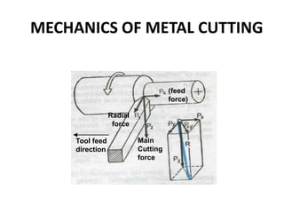
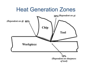
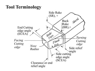
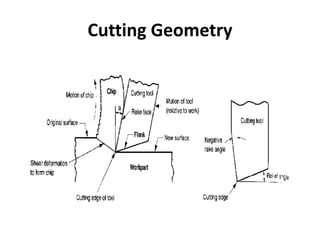
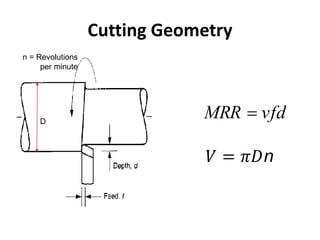
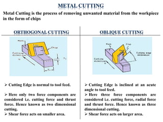
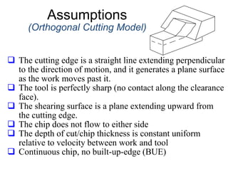
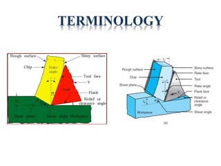
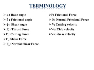
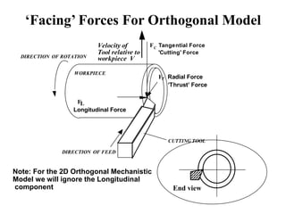
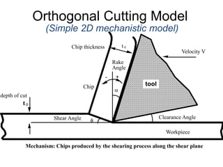
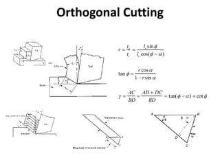
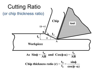
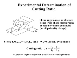
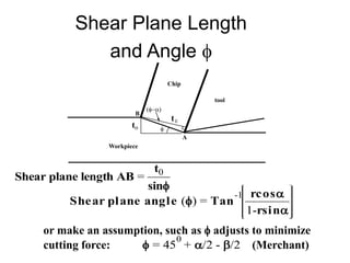
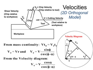
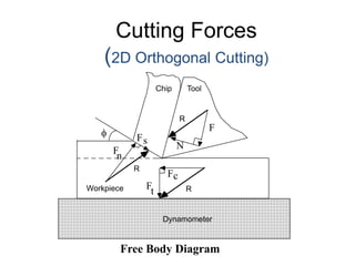
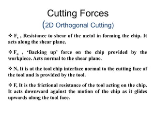
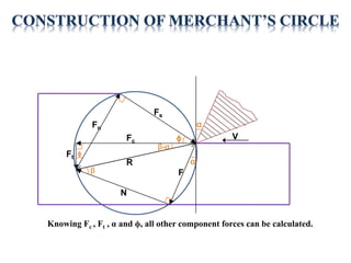
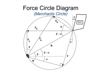
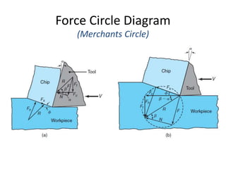
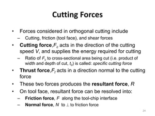
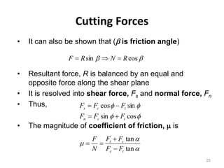
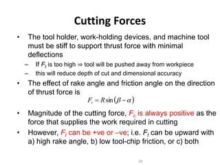
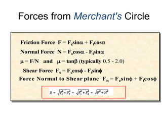
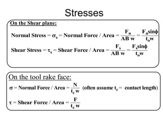
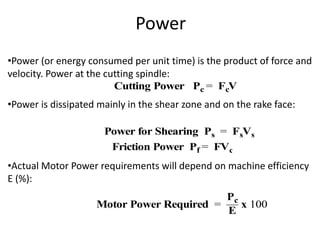
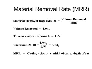
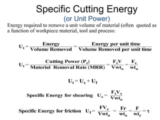
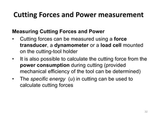
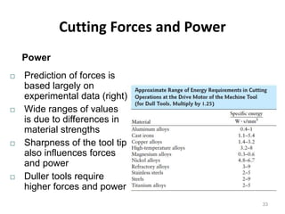
MECHANICS OF METAL CUTTING
(feed
force)
Main
Cutting
force
Radial
force
Tool feed
direction
Topics to be covered
 Tool terminologies and geometry
 Orthogonal Vs Oblique cutting
 Turning Forces
 Velocity diagram
 Merchants Circle
 Power & Energies
Need for calculating forces, velocities and
angles during machining??
• We need to determine the cutting forces in turning for
Estimation of cutting power consumption, which also enables
selection of the power source (e.g. motors) during design of the
machine tools.
• Structural design of the machine – fixture – tool system.
• Evaluation of role of the various machining parameters (tool
material and geometry) on cutting forces to make machining
process more efficient and economical.
• Condition monitoring of the cutting tools and machine tools.
Tool
Workpiece
Chip
Heat Generation Zones
(Dependent on sharpness
of tool)
(Dependent on m)
(Dependent on f)
10%
30%
60%
Tool Terminology
Side relief
angle
Side cutting
edge angle
(SCEA)
Clearance or end
relief angle
Back
Rake
(BR),+
Side Rake
(SR), +
End Cutting
edge angle
(ECEA)
Nose
Radius
Turning
Cutting
edge
Facing
Cutting
edge
Cutting Geometry
Cutting Geometry
vfd
MRR 
𝑉 = 𝜋𝐷n
D
n = Revolutions
per minute
 Cutting Edge is normal to tool feed.
 Here only two force components are
considered i.e. cutting force and thrust
force. Hence known as two dimensional
cutting.
 Shear force acts on smaller area.
 Cutting Edge is inclined at an acute
angle to tool feed.
 Here three force components are
considered i.e. cutting force, radial force
and thrust force. Hence known as three
dimensional cutting.
 Shear force acts on larger area.
Metal Cutting is the process of removing unwanted material from the workpiece
in the form of chips
Assumptions
(Orthogonal Cutting Model)
 The cutting edge is a straight line extending perpendicular
to the direction of motion, and it generates a plane surface
as the work moves past it.
 The tool is perfectly sharp (no contact along the clearance
face).
 The shearing surface is a plane extending upward from
the cutting edge.
 The chip does not flow to either side
 The depth of cut/chip thickness is constant uniform
relative to velocity between work and tool
 Continuous chip, no built-up-edge (BUE)
TERMINOLOGY
 α : Rake angle
 b : Frictional angle
 ϕ : Shear angle
 Ft : Thrust Force
Fc: Cutting Force
Fs: Shear Force
 Fn: Normal Shear Force
F: Frictional Force
 N: Normal Frictional Force
 V: Cutting velocity
Vc: Chip velocity
Vs: Shear velocity
FL
FC
Fr
DIRECTION OF ROTATION
WORKPIECE
CUTTING TOOL
DIRECTION OF FEED
Velocity of
Tool relative to
workpiece V
Longitudinal Force
Radial Force
‘Thrust’ Force
Tangential Force
'Cutting' Force
‘Facing’ Forces For Orthogonal Model
End view
Note: For the 2D Orthogonal Mechanistic
Model we will ignore the Longitudinal
component
Orthogonal Cutting Model
(Simple 2D mechanistic model)
Mechanism: Chips produced by the shearing process along the shear plane
a
t0
f
+
Rake
Angle
Chip
Workpiece
Clearance Angle
Shear Angle
t c
depth of cut
Chip thickness
Tool
Velocity V
tool
-
Orthogonal Cutting
r 
to
tc

ls sinf
ls cos(f  a)
tan f 
r cosa
1  rsin a
 
AC
BD

AD  DC
BD
 tan(f a)  cotf
tool
Cutting Ratio
(or chip thickness ratio)
As Sinf =
to
AB
and Cosf-a) =
tc
AB
Chip thickness ratio (r) =
t0
tc
=
sinf
cos(fa)
f
tc
to
fa)
A
B
Chip
Workpiece
Experimental Determination of
Cutting Ratio
Shear angle f may be obtained
either from photo-micrographs
or assume volume continuity
(no chip density change):
Since t0w0L0 = tcwcLc and w0=wc (exp. evidence)
Cutting ratio , r = t0
tc
= Lc
L0
i.e. Measure length of chips which is easier than measuring thickness
w
t
L
0
0
0
wc
Lc
c
t
Shear Plane Length
and Angle f
Shear plane length AB =
t0
sinf
Shear plane angle (f) = Tan
-1 rcosa
1-rsina
or make an assumption, such as f adjusts to minimize
cutting force: f = 45
0
+ a/2 - b/2 (Merchant)
f
tc
to
fa)
A
B
Chip
tool
Workpiece
Velocities
(2D Orthogonal
Model)
Velocity Diagram
From mass continuity: Vto = Vctc
From the Velocity diagram:
Vs = V
cosa
cos(fa)
Vc = Vr and Vc = V
sinf
cos(fa)
(Chip relative
to workpiece)
V = Chip Velocity
(Chip relative to tool)
Tool
Workpiece
Chip
V
s V = Cutting Velocity
(Tool relative to
workpiece)
Shear Velocity
c
a
f  a
90  f f
Vs
V c
V
Cutting Forces
(2D Orthogonal Cutting)
Free Body Diagram
Tool
Workpiece
Chip
Dynamometer
R
R
R
Fc
Ft
f
s
F
F
n
N
F
 Fs , Resistance to shear of the metal in forming the chip. It
acts along the shear plane.
 Fn , ‘Backing up’ force on the chip provided by the
workpiece. Acts normal to the shear plane.
 N, It is at the tool chip interface normal to the cutting face of
the tool and is provided by the tool.
 F, It is the frictional resistance of the tool acting on the chip.
It acts downward against the motion of the chip as it glides
upwards along the tool face.
Cutting Forces
(2D Orthogonal Cutting)
Fn
Ft
Fs
Fc
F
R
α
α
ϕ
β
ϕ
β-α
N
V
Knowing Fc , Ft , α and ϕ, all other component forces can be calculated.
Force Circle Diagram
(Merchants Circle)
R
F
t
Fc
Tool
F
N
a
b  a
b
a
a
Fs
f
b  a
f
F
n
Force Circle Diagram
(Merchants Circle)
Cutting Forces
• Forces considered in orthogonal cutting include
– Cutting, friction (tool face), and shear forces
• Cutting force,Fc acts in the direction of the cutting
speed V, and supplies the energy required for cutting
– Ratio of Fc to cross-sectional area being cut (i.e. product of
width and depth of cut, t0) is called: specific cutting force
• Thrust force,Ft acts in a direction normal to the cutting
force
• These two forces produces the resultant force, R
• On tool face, resultant force can be resolved into:
– Friction force, F along the tool-chip interface
– Normal force, N to  to friction force
24
Cutting Forces
• It can also be shown that (b is friction angle)
• Resultant force, R is balanced by an equal and
opposite force along the shear plane
• It is resolved into shear force, Fs and normal force, Fn
• Thus,
• The magnitude of coefficient of friction, m is
25
b
b cos
sin R
N
R
F 


f
f
f
f
cos
sin
sin
cos
t
c
n
t
c
s
F
F
F
F
F
F




a
a
m
tan
tan
t
c
c
t
F
F
F
F
N
F




Cutting Forces
• The tool holder, work-holding devices, and machine tool
must be stiff to support thrust force with minimal
deflections
– If Ft is too high ⇒ tool will be pushed away from workpiece
– this will reduce depth of cut and dimensional accuracy
• The effect of rake angle and friction angle on the direction
of thrust force is
• Magnitude of the cutting force, Fc is always positive as the
force that supplies the work required in cutting
• However, Ft can be +ve or –ve; i.e. Ft can be upward with
a) high rake angle, b) low tool-chip friction, or c) both
26
 )
a
b 
 sin
R
Ft
Forces from Merchant's Circle
Friction Force F = Fcsina + Ftcosa
Normal Force N = Fccosa - Ftsina
Shear Force Fs = Fccosf - Ftsinf
m = F/N and m = tanb typically 0.5 - 2.0)
Force Normal to Shear plane Fn = Fcsinf + Ftcosf
Stresses
On the Shear plane:
Normal Stress = s = Normal Force / Area =
Fn
AB w
=
Fnsinf
tow
Shear Stress = s = Shear Force / Area =
Fs
AB w
=
Fssinf
tow
On the tool rake face:
 = Normal Force / Area =
N
tc w
(often assume tc = contact length)
 = Shear Force / Area =
F
tc w
Power
•Power (or energy consumed per unit time) is the product of force and
velocity. Power at the cutting spindle:
•Power is dissipated mainly in the shear zone and on the rake face:
•Actual Motor Power requirements will depend on machine efficiency
E (%):
Cutting Power Pc = FcV
Power for Shearing Ps = FsVs
Friction Power Pf = FVc
Motor Power Required =
Pc
E
x 100
Material Removal Rate (MRR)
Material Removal Rate (MRR) =
Volume Removed
Time
Volume Removed = Lwto
Time to move a distance L = L/V
Therefore, MRR =
Lwto
L/V
= Vwto
MRR = Cutting velocity x width of cut x depth of cut
Specific Cutting Energy
(or Unit Power)
Energy required to remove a unit volume of material (often quoted as
a function of workpiece material, tool and process:
Ut =
Energy
Volume Removed
=
Energy per unit time
Volume Removed per unit time
Specific Energy for shearing Us =
FsVs
Vwto
Ut =
Cutting Power (Pc)
Material Removal Rate (MRR)
=
FcV
Vwto
=
Fc
wto
Specific Energy for friction Uf =
FVc
Vwto
=
Fr
wto
=
F
wtc
= 
Ut = Us + Uf +Uc +Um
Cutting Forces and Power measurement
Measuring Cutting Forces and Power
• Cutting forces can be measured using a force
transducer, a dynamometer or a load cell mounted
on the cutting-tool holder
• It is also possible to calculate the cutting force from the
power consumption during cutting (provided
mechanical efficiency of the tool can be determined)
• The specific energy (u) in cutting can be used to
calculate cutting forces
32
Cutting Forces and Power
Power
33
 Prediction of forces is
based largely on
experimental data (right)
 Wide ranges of values
is due to differences in
material strengths
 Sharpness of the tool tip
also influences forces
and power
 Duller tools require
higher forces and power

3142509_Mechanics_of_Metal_Cutting_1777.pptx

  • 1.
    MECHANICS OF METALCUTTING (feed force) Main Cutting force Radial force Tool feed direction
  • 2.
    Topics to becovered  Tool terminologies and geometry  Orthogonal Vs Oblique cutting  Turning Forces  Velocity diagram  Merchants Circle  Power & Energies
  • 3.
    Need for calculatingforces, velocities and angles during machining?? • We need to determine the cutting forces in turning for Estimation of cutting power consumption, which also enables selection of the power source (e.g. motors) during design of the machine tools. • Structural design of the machine – fixture – tool system. • Evaluation of role of the various machining parameters (tool material and geometry) on cutting forces to make machining process more efficient and economical. • Condition monitoring of the cutting tools and machine tools.
  • 4.
    Tool Workpiece Chip Heat Generation Zones (Dependenton sharpness of tool) (Dependent on m) (Dependent on f) 10% 30% 60%
  • 5.
    Tool Terminology Side relief angle Sidecutting edge angle (SCEA) Clearance or end relief angle Back Rake (BR),+ Side Rake (SR), + End Cutting edge angle (ECEA) Nose Radius Turning Cutting edge Facing Cutting edge
  • 6.
  • 7.
    Cutting Geometry vfd MRR  𝑉= 𝜋𝐷n D n = Revolutions per minute
  • 8.
     Cutting Edgeis normal to tool feed.  Here only two force components are considered i.e. cutting force and thrust force. Hence known as two dimensional cutting.  Shear force acts on smaller area.  Cutting Edge is inclined at an acute angle to tool feed.  Here three force components are considered i.e. cutting force, radial force and thrust force. Hence known as three dimensional cutting.  Shear force acts on larger area. Metal Cutting is the process of removing unwanted material from the workpiece in the form of chips
  • 9.
    Assumptions (Orthogonal Cutting Model) The cutting edge is a straight line extending perpendicular to the direction of motion, and it generates a plane surface as the work moves past it.  The tool is perfectly sharp (no contact along the clearance face).  The shearing surface is a plane extending upward from the cutting edge.  The chip does not flow to either side  The depth of cut/chip thickness is constant uniform relative to velocity between work and tool  Continuous chip, no built-up-edge (BUE)
  • 10.
  • 11.
     α :Rake angle  b : Frictional angle  ϕ : Shear angle  Ft : Thrust Force Fc: Cutting Force Fs: Shear Force  Fn: Normal Shear Force F: Frictional Force  N: Normal Frictional Force  V: Cutting velocity Vc: Chip velocity Vs: Shear velocity
  • 12.
    FL FC Fr DIRECTION OF ROTATION WORKPIECE CUTTINGTOOL DIRECTION OF FEED Velocity of Tool relative to workpiece V Longitudinal Force Radial Force ‘Thrust’ Force Tangential Force 'Cutting' Force ‘Facing’ Forces For Orthogonal Model End view Note: For the 2D Orthogonal Mechanistic Model we will ignore the Longitudinal component
  • 13.
    Orthogonal Cutting Model (Simple2D mechanistic model) Mechanism: Chips produced by the shearing process along the shear plane a t0 f + Rake Angle Chip Workpiece Clearance Angle Shear Angle t c depth of cut Chip thickness Tool Velocity V tool -
  • 14.
    Orthogonal Cutting r  to tc  lssinf ls cos(f  a) tan f  r cosa 1  rsin a   AC BD  AD  DC BD  tan(f a)  cotf
  • 15.
    tool Cutting Ratio (or chipthickness ratio) As Sinf = to AB and Cosf-a) = tc AB Chip thickness ratio (r) = t0 tc = sinf cos(fa) f tc to fa) A B Chip Workpiece
  • 16.
    Experimental Determination of CuttingRatio Shear angle f may be obtained either from photo-micrographs or assume volume continuity (no chip density change): Since t0w0L0 = tcwcLc and w0=wc (exp. evidence) Cutting ratio , r = t0 tc = Lc L0 i.e. Measure length of chips which is easier than measuring thickness w t L 0 0 0 wc Lc c t
  • 17.
    Shear Plane Length andAngle f Shear plane length AB = t0 sinf Shear plane angle (f) = Tan -1 rcosa 1-rsina or make an assumption, such as f adjusts to minimize cutting force: f = 45 0 + a/2 - b/2 (Merchant) f tc to fa) A B Chip tool Workpiece
  • 18.
    Velocities (2D Orthogonal Model) Velocity Diagram Frommass continuity: Vto = Vctc From the Velocity diagram: Vs = V cosa cos(fa) Vc = Vr and Vc = V sinf cos(fa) (Chip relative to workpiece) V = Chip Velocity (Chip relative to tool) Tool Workpiece Chip V s V = Cutting Velocity (Tool relative to workpiece) Shear Velocity c a f  a 90  f f Vs V c V
  • 19.
    Cutting Forces (2D OrthogonalCutting) Free Body Diagram Tool Workpiece Chip Dynamometer R R R Fc Ft f s F F n N F
  • 20.
     Fs ,Resistance to shear of the metal in forming the chip. It acts along the shear plane.  Fn , ‘Backing up’ force on the chip provided by the workpiece. Acts normal to the shear plane.  N, It is at the tool chip interface normal to the cutting face of the tool and is provided by the tool.  F, It is the frictional resistance of the tool acting on the chip. It acts downward against the motion of the chip as it glides upwards along the tool face. Cutting Forces (2D Orthogonal Cutting)
  • 21.
    Fn Ft Fs Fc F R α α ϕ β ϕ β-α N V Knowing Fc ,Ft , α and ϕ, all other component forces can be calculated.
  • 22.
    Force Circle Diagram (MerchantsCircle) R F t Fc Tool F N a b  a b a a Fs f b  a f F n
  • 23.
  • 24.
    Cutting Forces • Forcesconsidered in orthogonal cutting include – Cutting, friction (tool face), and shear forces • Cutting force,Fc acts in the direction of the cutting speed V, and supplies the energy required for cutting – Ratio of Fc to cross-sectional area being cut (i.e. product of width and depth of cut, t0) is called: specific cutting force • Thrust force,Ft acts in a direction normal to the cutting force • These two forces produces the resultant force, R • On tool face, resultant force can be resolved into: – Friction force, F along the tool-chip interface – Normal force, N to  to friction force 24
  • 25.
    Cutting Forces • Itcan also be shown that (b is friction angle) • Resultant force, R is balanced by an equal and opposite force along the shear plane • It is resolved into shear force, Fs and normal force, Fn • Thus, • The magnitude of coefficient of friction, m is 25 b b cos sin R N R F    f f f f cos sin sin cos t c n t c s F F F F F F     a a m tan tan t c c t F F F F N F    
  • 26.
    Cutting Forces • Thetool holder, work-holding devices, and machine tool must be stiff to support thrust force with minimal deflections – If Ft is too high ⇒ tool will be pushed away from workpiece – this will reduce depth of cut and dimensional accuracy • The effect of rake angle and friction angle on the direction of thrust force is • Magnitude of the cutting force, Fc is always positive as the force that supplies the work required in cutting • However, Ft can be +ve or –ve; i.e. Ft can be upward with a) high rake angle, b) low tool-chip friction, or c) both 26  ) a b   sin R Ft
  • 27.
    Forces from Merchant'sCircle Friction Force F = Fcsina + Ftcosa Normal Force N = Fccosa - Ftsina Shear Force Fs = Fccosf - Ftsinf m = F/N and m = tanb typically 0.5 - 2.0) Force Normal to Shear plane Fn = Fcsinf + Ftcosf
  • 28.
    Stresses On the Shearplane: Normal Stress = s = Normal Force / Area = Fn AB w = Fnsinf tow Shear Stress = s = Shear Force / Area = Fs AB w = Fssinf tow On the tool rake face:  = Normal Force / Area = N tc w (often assume tc = contact length)  = Shear Force / Area = F tc w
  • 29.
    Power •Power (or energyconsumed per unit time) is the product of force and velocity. Power at the cutting spindle: •Power is dissipated mainly in the shear zone and on the rake face: •Actual Motor Power requirements will depend on machine efficiency E (%): Cutting Power Pc = FcV Power for Shearing Ps = FsVs Friction Power Pf = FVc Motor Power Required = Pc E x 100
  • 30.
    Material Removal Rate(MRR) Material Removal Rate (MRR) = Volume Removed Time Volume Removed = Lwto Time to move a distance L = L/V Therefore, MRR = Lwto L/V = Vwto MRR = Cutting velocity x width of cut x depth of cut
  • 31.
    Specific Cutting Energy (orUnit Power) Energy required to remove a unit volume of material (often quoted as a function of workpiece material, tool and process: Ut = Energy Volume Removed = Energy per unit time Volume Removed per unit time Specific Energy for shearing Us = FsVs Vwto Ut = Cutting Power (Pc) Material Removal Rate (MRR) = FcV Vwto = Fc wto Specific Energy for friction Uf = FVc Vwto = Fr wto = F wtc =  Ut = Us + Uf +Uc +Um
  • 32.
    Cutting Forces andPower measurement Measuring Cutting Forces and Power • Cutting forces can be measured using a force transducer, a dynamometer or a load cell mounted on the cutting-tool holder • It is also possible to calculate the cutting force from the power consumption during cutting (provided mechanical efficiency of the tool can be determined) • The specific energy (u) in cutting can be used to calculate cutting forces 32
  • 33.
    Cutting Forces andPower Power 33  Prediction of forces is based largely on experimental data (right)  Wide ranges of values is due to differences in material strengths  Sharpness of the tool tip also influences forces and power  Duller tools require higher forces and power

Editor's Notes

  • #19 http://engineeronadisk.com/notes_manufact/cuttinga7.html (use sine rule to prove the second one and also sin(90-a) = cos (a)) In the mass continuity equation actually is it (length x width x thickness) / Time...since width before and after cut is the same it cancels and length over time is Velocity