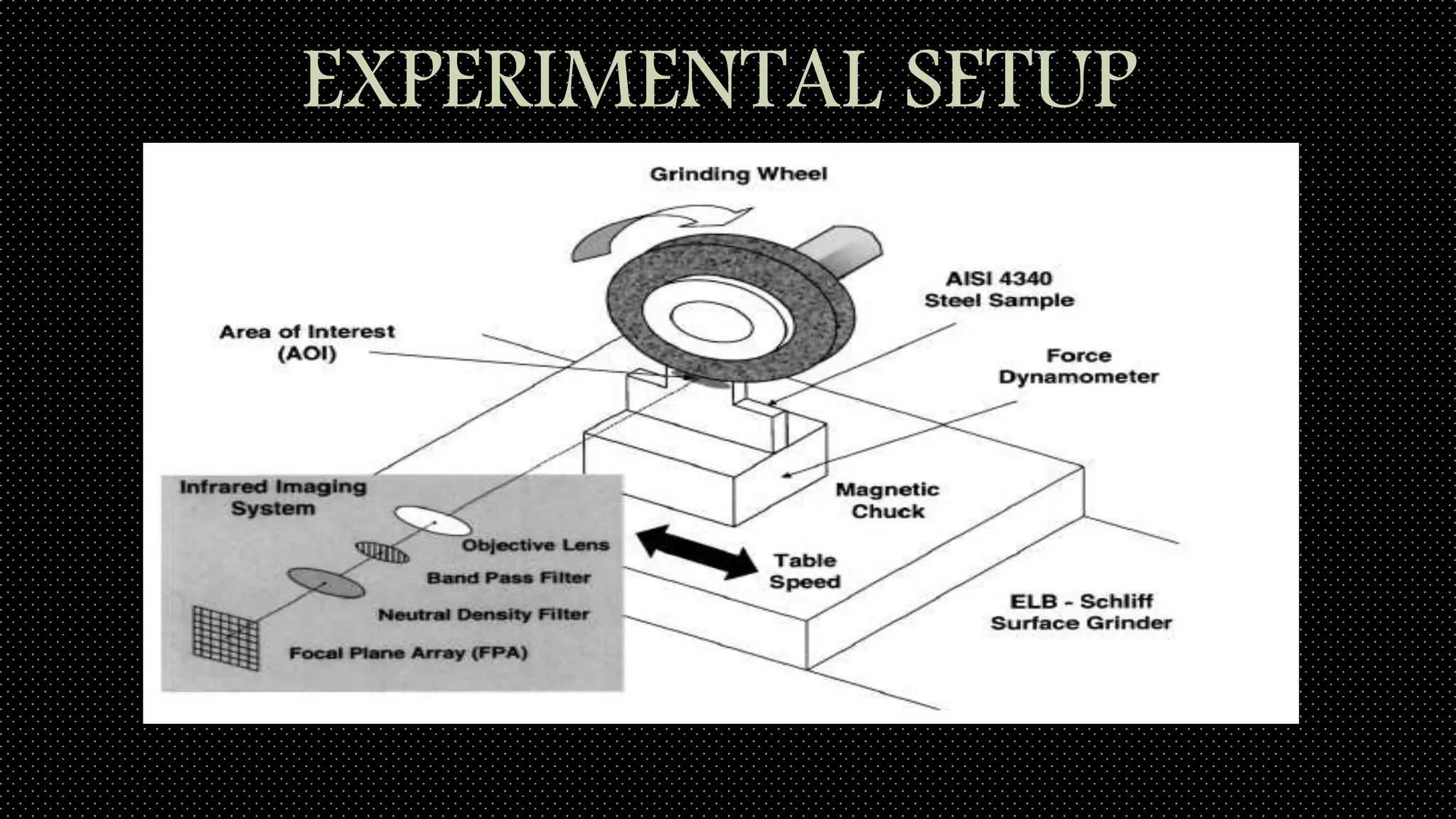
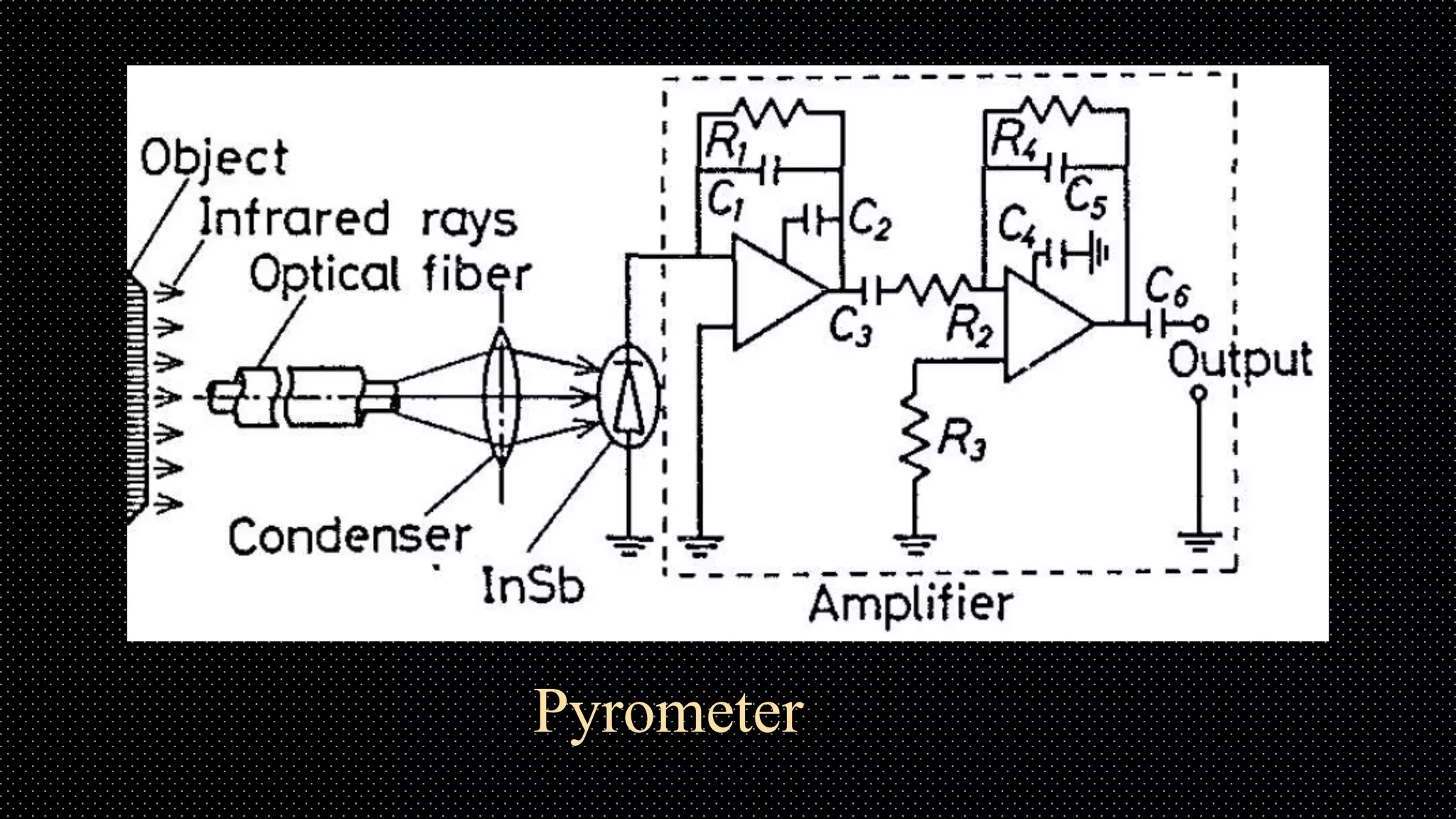
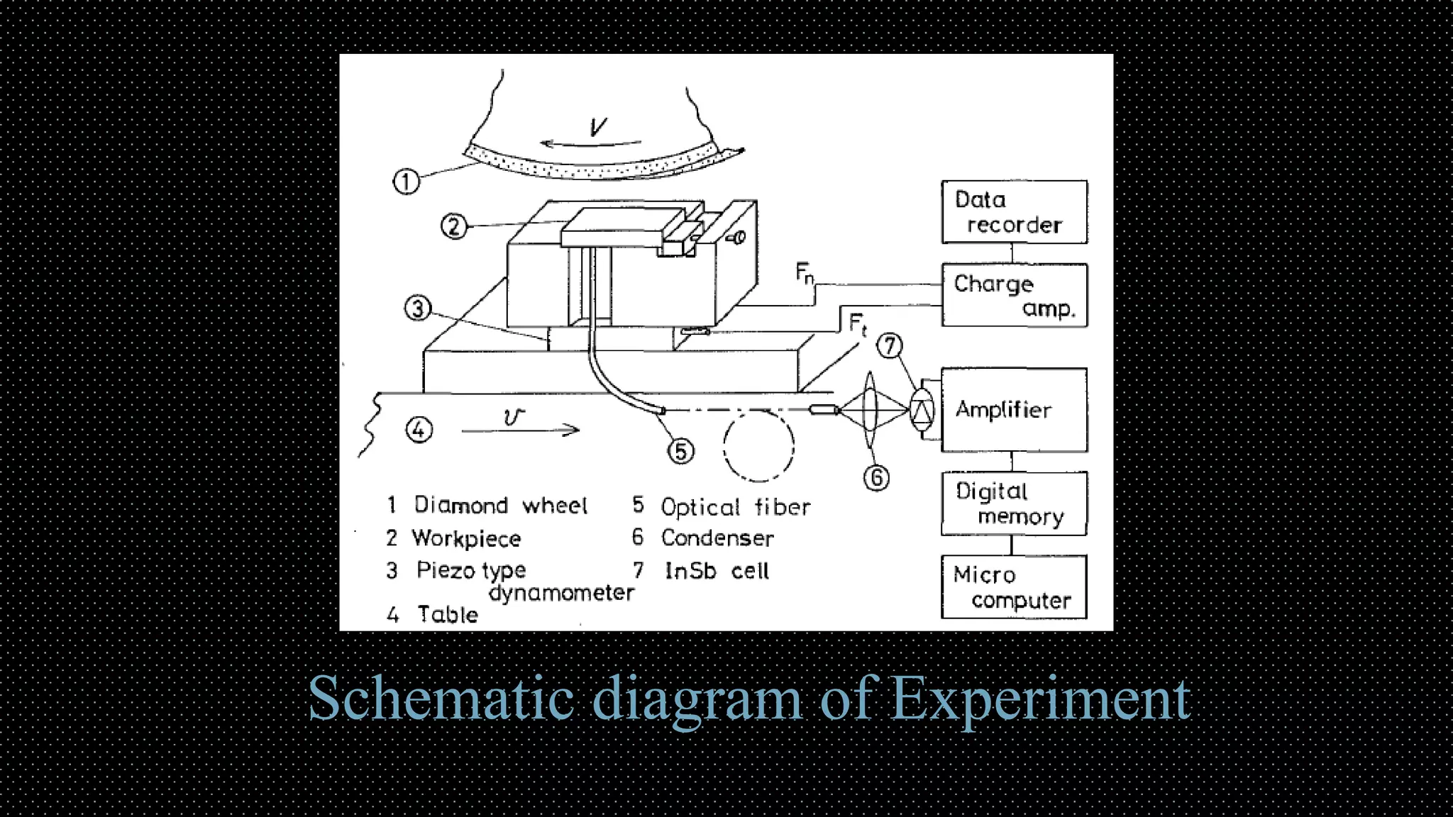
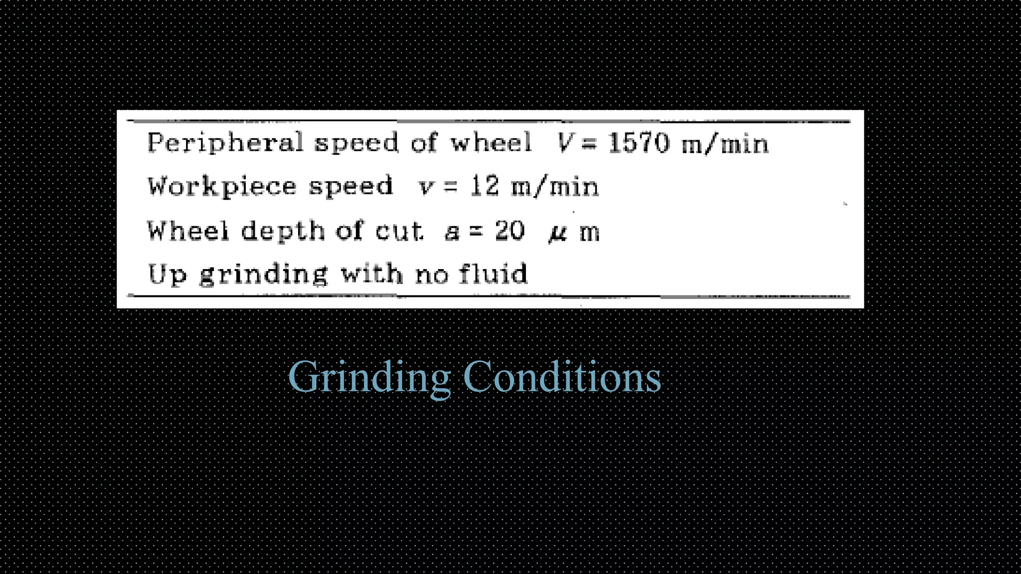
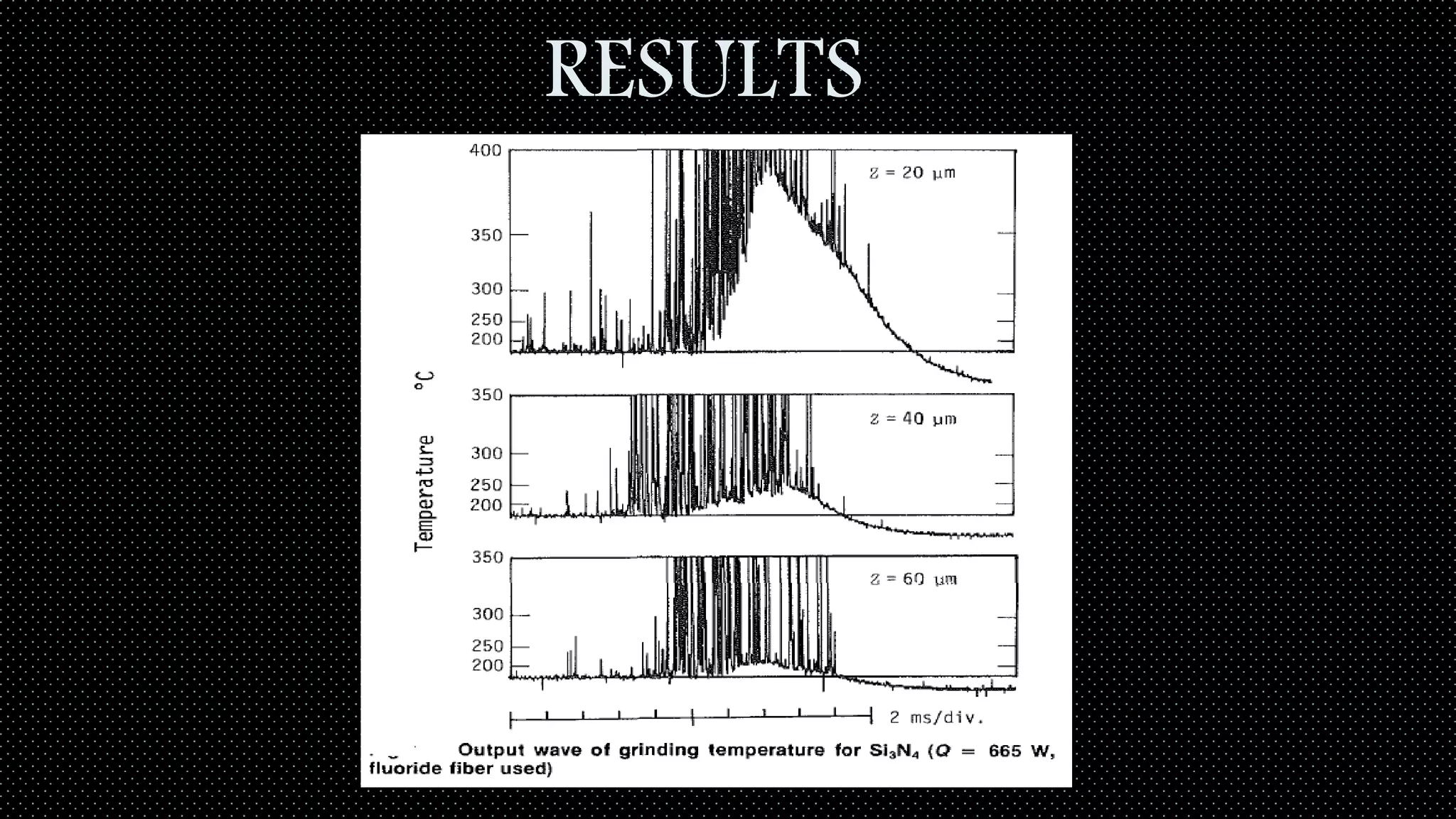
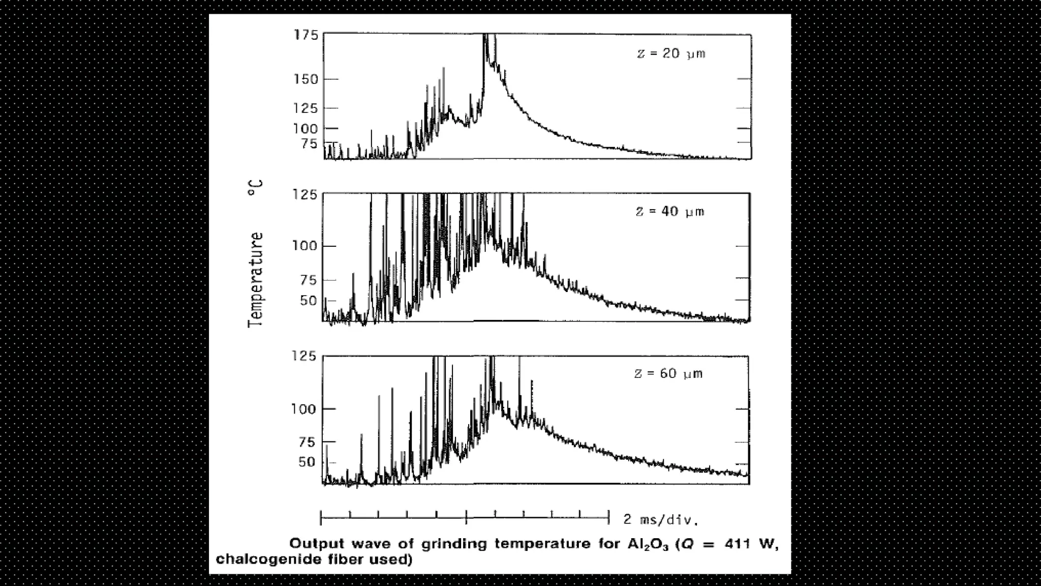
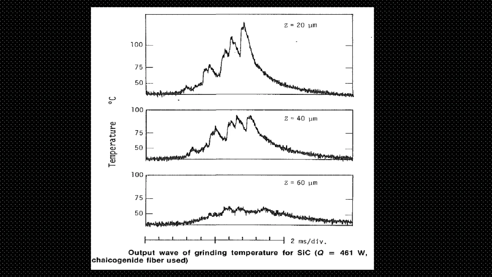
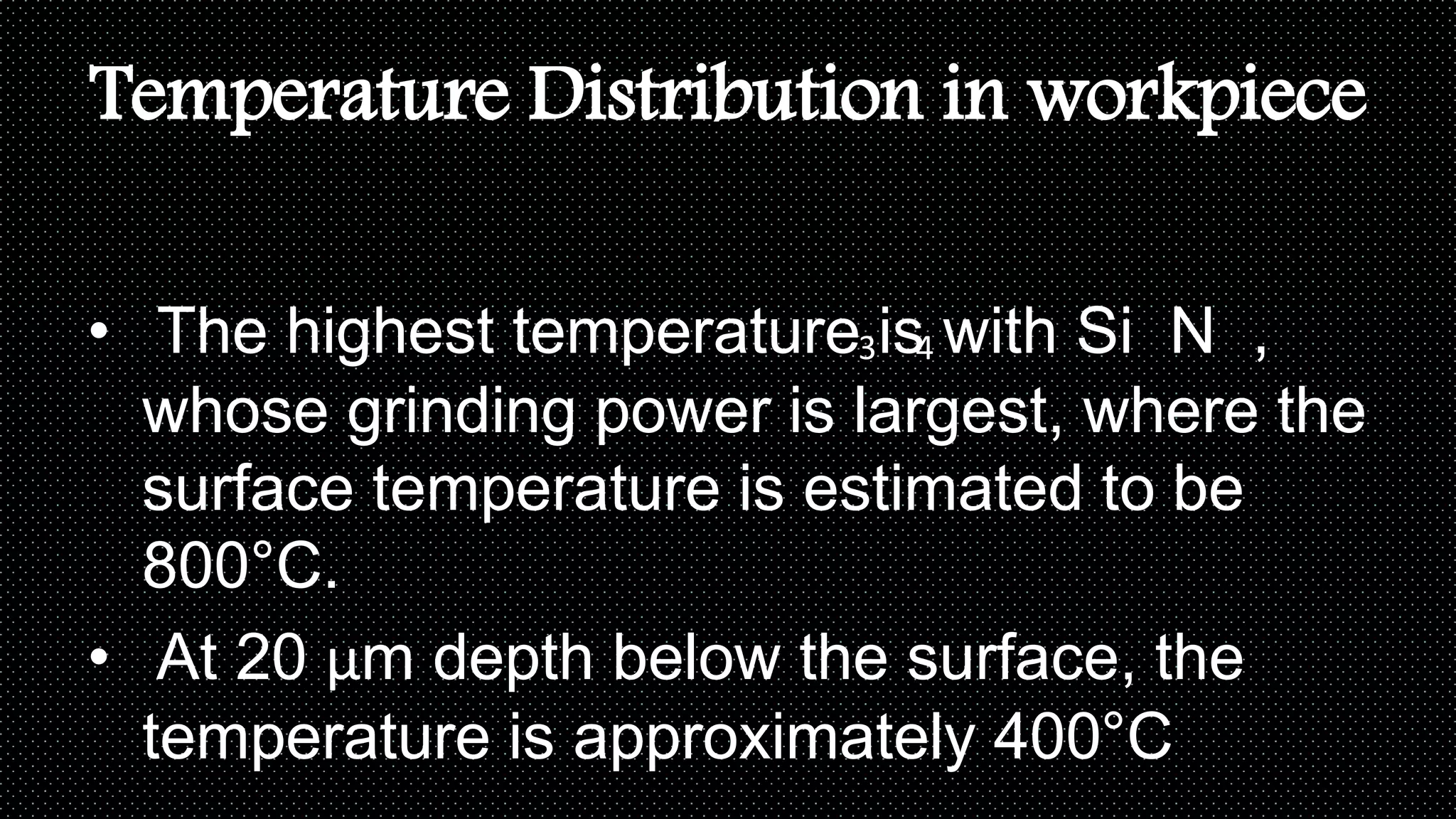
Measurement of Temperature
Field in Surface Grinding Using
Infra-Red (IR) Imaging System
PRESENTED BY - SAYAN MALLICK
ROLL NO - 16ME61R14
M.TECH (1st YEAR)
MANUFACTURING SCIENCE
IIT KHARAGPUR
CONTENTS
• INTRODUCTION
• OBJECTIVE
• Process description
• Experimental Method
• Results & Discussion
• Conclusion
• References
OBJECTIVE
• To measure grinding temperature with an
effective method of Infra-Red radiation
using optical fiber.
INTRODUCTION
• large amount of energy is expended for
material removal in grinding.
• Heat is generated resulting various faults
in machined surface
CONTINUED
• Grinding Burn
• A better understanding of thermal damage
is likely to be gained by a study of the
workpiece temperature field.
• The heart of the measurement technique
is a Charge-Coupled Device (CCD) based,
Infra-Red (IR) imaging system and
PROCESS DESCRIPTION
Pyrometer
 3 kinds of optical fiber is used.
 Quartz fiber, fluoride fiber and
chalcogenide fiber.
Characteristics of optical fiber
Spectral transmission loss of optical fibers
• The upper limit of the wavelength of light
transmission :-
Chalcogenide - 6 μm
Fluoride – 4 μm
Quartz – 2 μm
• The diameter of the chalcogenide fiber is
approximately 320 μm, which is about 6
Calibration
• Emissivity of material depends on many
factors.
• Such as Temperature, Surface finish and
wave length of radiation.
• Therefore the calibration curve of the three
versions of the pyrometer were obtained by
EXPERIMENTAL SETUP
Pyrometer
Schematic diagram of Experiment
Grinding Conditions
RESULTS
Temperature Distribution in workpiece
• The highest temperature is with Si N ,
whose grinding power is largest, where the
surface temperature is estimated to be
800°C.
• At 20 μm depth below the surface, the
temperature is approximately 400°C
43
• In the case of SiC and Al203 the
temperatures at 40 μm depth are only
100°C.
• The temperature gradients are smaller
than for Si3N4.
• the main reasons for this is that the
grinding powers are smaller than in the
CONCLUSION
• The grinding temperature of ceramics is
measured by an IRP with an optical fiber,
either a fluoride fiber or a chalcogenide fiber.
Si3N4, SiC, and Al203 are used as work
materials.
• For Si3N4 and Al203, the signal trace versus
time is observed as a curve with a great
many peaks, but for SiC there are no peaks.
• This phenomenon arises from the optical
properties of ceramics.
• The grinding temperature is highest in Si3N4,
whose grinding power is the largest for these
three materials.
•
• The temperature distribution in the surface
layer of ceramics was greatly different from
REFERECNES
• 1 Littmann, W. E, and Wulff, J., 1955, "The Influence of the Grinding
• Process on the Structure of Hardened Steel," Trans. ASM, Vol. 47, pp. 692-
• 714.
• 2 Takazawa, K., 1966, "Effects of Grinding Variables on the Surface Structure
• of Hardened Steel," Bull. Japan Soc. of Precision Engineering, Vol. 2,
• No. 1, Apr., pp. 14-19.
• ,3 Ueda, T., Hosokawa, A., and Yamamoto, A., 1985, "Studies on Temperature
• of Abrasive Grains in Grinding-Application of Infrared Radiation Pyrometer,"
• ASME JOURNAL OF ENGINEERING FOR INDUSTRY, Vol. 107, No. 2,
• pp. 127-133.
• 4 Ueda, T., Hosokawa, A., and Yamamoto, A., 1986, "Measurement of
• Grinding Temperature Using Infrared Radiation Pyrometer with Optical Fiber,"
• ASME JOURNAL OF ENGINEERING FOR INDUSTRY, Vol. 108, No. 4, pp. 247-251.
• 5 Yamagishi, T., 1989, "Chalcogenide Glass Fiber For Infrared Transmission,"
• New Glass., Vol. 3, No. 4, pp. 10-12.
• 6 Siegel, R., and Howell, J. R., 1972, Thermal Radiation Heat Transfer,
• McGraw-Hill Kogakushi, Ltd., pp. 42-78.
• 7 Touloukian, Y. S., and Ho, C. Y., 1972, "Thermophysical Properties of
• Matter," Plenum, 8
THANK YOU

Measurement of Grinding Temperature Field Using Infra-Red (IR) Imaging System

  • 1.
    Measurement of Temperature Fieldin Surface Grinding Using Infra-Red (IR) Imaging System PRESENTED BY - SAYAN MALLICK ROLL NO - 16ME61R14 M.TECH (1st YEAR) MANUFACTURING SCIENCE IIT KHARAGPUR
  • 2.
    CONTENTS • INTRODUCTION • OBJECTIVE •Process description • Experimental Method • Results & Discussion • Conclusion • References
  • 3.
    OBJECTIVE • To measuregrinding temperature with an effective method of Infra-Red radiation using optical fiber.
  • 4.
    INTRODUCTION • large amountof energy is expended for material removal in grinding. • Heat is generated resulting various faults in machined surface
  • 5.
    CONTINUED • Grinding Burn •A better understanding of thermal damage is likely to be gained by a study of the workpiece temperature field. • The heart of the measurement technique is a Charge-Coupled Device (CCD) based, Infra-Red (IR) imaging system and
  • 6.
    PROCESS DESCRIPTION Pyrometer  3kinds of optical fiber is used.  Quartz fiber, fluoride fiber and chalcogenide fiber.
  • 7.
  • 8.
    Spectral transmission lossof optical fibers
  • 9.
    • The upperlimit of the wavelength of light transmission :- Chalcogenide - 6 μm Fluoride – 4 μm Quartz – 2 μm • The diameter of the chalcogenide fiber is approximately 320 μm, which is about 6
  • 10.
    Calibration • Emissivity ofmaterial depends on many factors. • Such as Temperature, Surface finish and wave length of radiation. • Therefore the calibration curve of the three versions of the pyrometer were obtained by
  • 11.
  • 12.
  • 13.
  • 14.
  • 15.
  • 18.
    Temperature Distribution inworkpiece • The highest temperature is with Si N , whose grinding power is largest, where the surface temperature is estimated to be 800°C. • At 20 μm depth below the surface, the temperature is approximately 400°C 43
  • 19.
    • In thecase of SiC and Al203 the temperatures at 40 μm depth are only 100°C. • The temperature gradients are smaller than for Si3N4. • the main reasons for this is that the grinding powers are smaller than in the
  • 20.
    CONCLUSION • The grindingtemperature of ceramics is measured by an IRP with an optical fiber, either a fluoride fiber or a chalcogenide fiber. Si3N4, SiC, and Al203 are used as work materials. • For Si3N4 and Al203, the signal trace versus time is observed as a curve with a great many peaks, but for SiC there are no peaks.
  • 21.
    • This phenomenonarises from the optical properties of ceramics. • The grinding temperature is highest in Si3N4, whose grinding power is the largest for these three materials. • • The temperature distribution in the surface layer of ceramics was greatly different from
  • 22.
    REFERECNES • 1 Littmann,W. E, and Wulff, J., 1955, "The Influence of the Grinding • Process on the Structure of Hardened Steel," Trans. ASM, Vol. 47, pp. 692- • 714. • 2 Takazawa, K., 1966, "Effects of Grinding Variables on the Surface Structure • of Hardened Steel," Bull. Japan Soc. of Precision Engineering, Vol. 2, • No. 1, Apr., pp. 14-19. • ,3 Ueda, T., Hosokawa, A., and Yamamoto, A., 1985, "Studies on Temperature • of Abrasive Grains in Grinding-Application of Infrared Radiation Pyrometer," • ASME JOURNAL OF ENGINEERING FOR INDUSTRY, Vol. 107, No. 2, • pp. 127-133. • 4 Ueda, T., Hosokawa, A., and Yamamoto, A., 1986, "Measurement of • Grinding Temperature Using Infrared Radiation Pyrometer with Optical Fiber," • ASME JOURNAL OF ENGINEERING FOR INDUSTRY, Vol. 108, No. 4, pp. 247-251. • 5 Yamagishi, T., 1989, "Chalcogenide Glass Fiber For Infrared Transmission," • New Glass., Vol. 3, No. 4, pp. 10-12. • 6 Siegel, R., and Howell, J. R., 1972, Thermal Radiation Heat Transfer, • McGraw-Hill Kogakushi, Ltd., pp. 42-78. • 7 Touloukian, Y. S., and Ho, C. Y., 1972, "Thermophysical Properties of • Matter," Plenum, 8
  • 23.