Download as PDF, PPTX

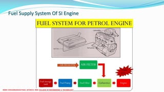
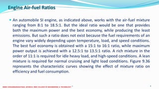
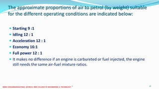
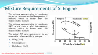
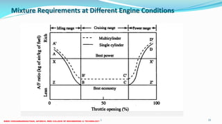
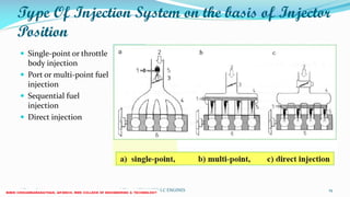
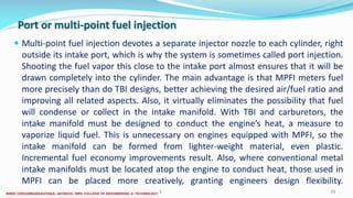
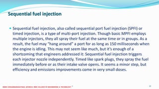
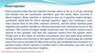
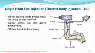
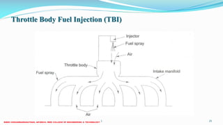
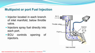
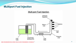
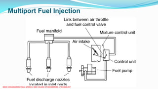

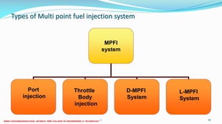
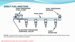
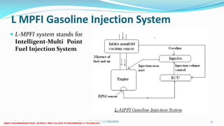
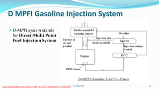
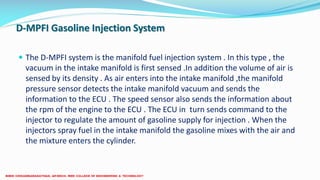
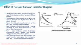
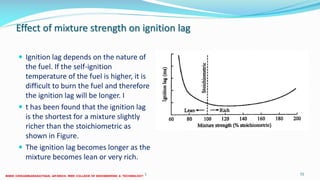
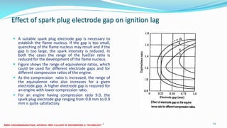


This document discusses fuel supply systems and air-fuel ratio requirements for spark ignition engines. It begins by describing the stages of the fuel supply system, including filtration, atomization and the need to finely disperse fuel before combustion. It then discusses the various fuel injection systems used in SI engines, including single-point/throttle body injection where fuel is injected into the throttle body, multi-point/port injection where each cylinder has a dedicated injector, and direct injection where fuel is injected directly into the combustion chamber. The document focuses on the air-fuel ratio requirements for SI engines under different operating conditions such as idling, cruising and high power, and explains why richer or leaner mixtures are needed depending on the situation.


