Download as PDF, PPTX

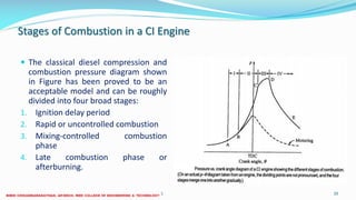
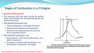
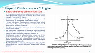
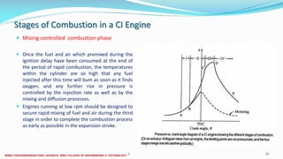
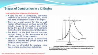
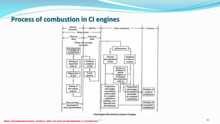

The document discusses the stages of combustion in a compression ignition (diesel) engine. It describes four stages: 1) ignition delay period, where fuel is injected and mixes with air before igniting; 2) rapid uncontrolled combustion, where ignition occurs rapidly across the cylinder; 3) mixing-controlled combustion phase, where combustion is controlled by fuel injection rate and mixing; 4) late combustion or afterburning phase, where any remaining fuel continues burning slowly through the expansion stroke. The document explains the physical and chemical processes that occur during each stage.


