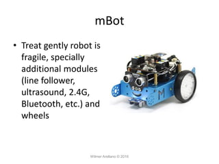
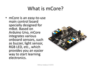
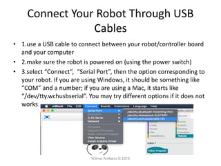
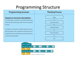
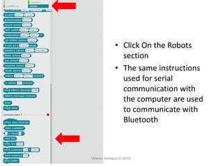
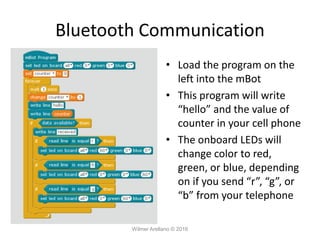
m-Block
By Wilmer Arellano
Wilmer Arellano © 2016
• You are free:
– to Share — to copy, distribute and transmit the work
• Under the following conditions:
– Attribution — You must attribute the work in the manner
specified by the author or licensor (but not in any way that
suggests that they endorse you or your use of the work).
– Noncommercial — You may not use this work for
commercial purposes.
– No Derivative Works — You may not alter, transform, or
build upon this work.
Wilmer Arellano © 2016
• With the understanding that:
– Public Domain — Where the work or any of its elements is in the public
domain under applicable law, that status is in no way affected by the
license.
– Other Rights — In no way are any of the following rights affected by the
license:
• Your fair dealing or fair use rights, or other applicable copyright exceptions and
limitations;
• The author's moral rights;
• Rights other persons may have either in the work itself or in how the work is used, such
as publicity or privacy rights.
– Notice — For any reuse or distribution, you must make clear to others the
license terms of this work.
Wilmer Arellano © 2016
mBot
• mBot is an all-in-one
solution for kids to enjoy
the hands-on experience
about programming,
electronics, and robotics.
Working with mBlock
inspired by Scratch 2.0,
you can use Bluetooth or
2.4GHz wireless module
to connect with mBot (By
different version), this
easy-to-assemble mBot
Wilmer Arellano © 2016
mBot
• Treat gently robot is
fragile, specially
additional modules
(line follower,
ultrasound, 2.4G,
Bluetooth, etc.) and
wheels
Wilmer Arellano © 2016
What is mCore?
• mCore is an easy-to-use
main control board
specially designed for
mBot. Based on
Arduino Uno, mCore
integrates various
onboard sensors, such
as buzzer, light sensor,
RGB LED, etc., which
provides you an easier
way to start learning
electronics.
Wilmer Arellano © 2016
What is mCore?
Wilmer Arellano © 2016
mBlock
• mBlock is a graphical programming environment based on
Scratch 2.0 Open Source Code that makes it easy to program
Arduino projects and create interactive applications.
Wilmer Arellano © 2016
Tutorials
• Resources page
• Scratch Tutorial
• m-Block Tutorial
Wilmer Arellano © 2016
Connect Your Robot Through USB
Cables
• 1.use a USB cable to connect between your robot/controller board
and your computer
• 2.make sure the robot is powered on (using the power switch)
• 3.select “Connect”, “Serial Port”, then the option corresponding to
your robot. If you are using Windows, it should be something like
“COM” and a number; if you are using a Mac, it starts like
“/dev/tty.wchusbserial”. You may try different options if it does not
works.
Wilmer Arellano © 2016
Programming Structure
Wilmer Arellano © 2016
Programming Structure
Wilmer Arellano © 2016
Play a Tone Example 1
Wilmer Arellano © 2016
Loading Programs to the Robot
Wilmer Arellano © 2016
Connect Your Robot Through 2.4G
Modules
• In this mode, the program runs in the
computer which sends instructions to the
robot on the actions to perform.
• This is an interesting feature for applications
as the remote control operation illustrated
bellow.
• For most applications it is not the preferred
way of operating the robot.
Wilmer Arellano © 2016
Connect Your Robot Through 2.4G
Modules
• The 2.4G module set comes with a electronic module and a USB dongle. If
your are using the dongle first time, you need to connect the 2.4G
electronic module to your robot; power up your robot; press the button
on top of the 2.4G module, and then plug the dongle to your computer.
When the LED light on the module turns from blinking to steady lighting, it
means the 2.4G module is paired with the dongle.
• On the software side, after pairing the dongle you need to select Connect-
>2.4G Serial->Connect in the software menu. When “Connected” is shown
in the title bar, you know your mBot is connected to the computer.
Wilmer Arellano © 2016
Connect Your Robot Through 2.4G
Modules
• Connect with USB cable
• Upgrade Firmware
• Close Program
• Turn off m-Robot
• Open Program
• Turn On Robot
• Connect with 2.4G
Wilmer Arellano © 2016
Play a Tone Example 2
Wilmer Arellano © 2016
Remote Control
• Select the xy-grid backdrop
Wilmer Arellano © 2016
Remote Control
• Delete the image on costume 1 of the Panda
Wilmer Arellano © 2016
Remote Control
Wilmer Arellano © 2016
Functions
• A function is a group of statements that together
perform a task.
• Functions are a utilized to make programs:
– Easier to understand
– Easier to troubleshoot
• As it can be observed in next slide, the main program
can be written as macro instructions.
• These macro instructions will be executed one by one,
as described in the definitions.
• It may be convenient to program a robot using
functions, one per robot task.
Wilmer Arellano © 2016
Functions
• This example is for the mBlock and the
onboard LEDs
Wilmer Arellano © 2016
Functions
Wilmer Arellano © 2016
Functions
• This example is for an Arduino board with an
LED connected to pin 9.
Wilmer Arellano © 2016
Functions
Wilmer Arellano © 2016
Observe how the ledOn and
LedOff blocks are
represented in Arduino
language.
void ledOn()
{
digitalWrite(9,1);
_delay(1);
}
void LedOff()
{
digitalWrite(9,0);
_delay(1);
}
void setup(){
pinMode(9,OUTPUT);
}
void loop(){
ledOn();
LedOff();
_loop();
}
void _delay(float seconds){
long endTime = millis() + seconds * 1000;
while(millis() < endTime)_loop();
}
void _loop(){
}
Code typed directly on Arduino Ide
void _delay(float seconds){
long endTime = millis() + seconds * 1000;
while(millis() < endTime)
_loop();
void _delay(float seconds){
long endTime = millis() + seconds * 1000;
while(millis() < endTime){
_loop();
}
Other versions of the _loop() function
millis(): Returns the number of milliseconds
since the Arduino board began running the
current program. This number will overflow
(go back to zero), after approximately 50 days.
Wilmer Arellano © 2016
void ledOn()
{
digitalWrite(9,1);
delay(1000);
}
void LedOff()
{
digitalWrite(9,0);
delay(1000);
}
void setup(){
pinMode(9,OUTPUT);
}
void loop(){
ledOn();
LedOff();
}
Simplified code on Arduino Ide
Wilmer Arellano © 2016
int frequency;
void ledOn()
{
digitalWrite(9,1);
frequency = 1000;
_delay(1);
}
void LedOff()
{
digitalWrite(9,0);
frequency = 500;
_delay(1);
}
void setup(){
pinMode(9,OUTPUT);
}
void loop(){
ledOn();
LedOff();
_loop();
}
void _delay(float seconds){
long endTime = millis() + seconds * 1000;
while(millis() < endTime)_loop();
}
void _loop(){
tone(8, frequency);
delay(100);
noTone(8);
delay(100);
}
Advantages of the _loop() function
You can execute instructions
while waiting
Wilmer Arellano © 2016
/*
* “Hello World!”
* This is the Hello World! for Arduino.
* It shows how to send data to the computer
*/
void setup() // run once, when the sketch starts
{
Serial.begin(9600); // set up Serial library at 9600 bps
Serial.println("Is anybody out there?"); // prints phrase with ending
line break
}
void loop() // run over and over again
{
// do nothing!
}
// After sending program to the Arduino, press Reset button on the board
and watch Serial monitor
Wilmer Arellano © 2016
/*
Function Example
*/
float quotient;
void setup(){
Serial.begin(9600);
quotient = divide1(7, 2);
Serial.print("divide1 ");
Serial.println (quotient);
Serial.print("divide2 ");
Serial.println (divide2(7, 2));
}
void loop(){
}
/* This function will return 3.00 even though
it has a float type. This is because calculation is
based on integers (integer math) */
float divide1(int dividend, int divisor){
float result;
result = dividend/divisor;
return result;
}
/* This function will return 3.50 the cast (type)with
argument float forces float math */
float divide2(int dividend, int divisor){
float result;
result = (float)dividend/divisor;
return result;
}
Wilmer Arellano © 2016
Testing The Ultrasonic sensor
• This program will allow to send distance
measured by the ultrasonic sensor to a
computer.
• A USB cable must be used to connect the
robot to de computer.
• Port must be selected in mBlock and in
Arduino IDE.
Wilmer Arellano © 2016
Click Here
Wilmer Arellano © 2016
Distance readings will be sent to computer
Select right speed
Wilmer Arellano © 2016
Bluetooth Communication
• Bluetooth communication is easy with the
mBot
• We will illustrate with a program that sends
and receives text.
• Connect the Bluetooth module to the mBot
Wilmer Arellano © 2016
Bluetooth Communication
• We will explain Bluetooth
communication for the
Android App
– Serial Bluetooth Terminal
• Install the App in your
phone
Wilmer Arellano © 2016
Bluetooth Communication
• Navigate to Devices
• Select Bluetooth LE
• Click Scan
• Press and hold
Mackeblock for further
configuration
Wilmer Arellano © 2016
Bluetooth Communication
• Select Custom
• Press and hold each of
the three bottom fields
and select to the image
Wilmer Arellano © 2016
Bluetooth Communication
• Navigate to Settings
• Press and hold Send
and select “LF”
Wilmer Arellano © 2016
Bluetooth Communication
• Navigate to Terminal
• Click on Connect
• You are ready to start
sending your
commands
Wilmer Arellano © 2016
• Select The
communication
extension
Wilmer Arellano © 2016
• Click On the Robots
section
• The same instructions
used for serial
communication with
the computer are used
to communicate with
Bluetooth
Wilmer Arellano © 2016
Bluetooth Communication
• Load the program on the
left into the mBot
• This program will write
“hello” and the value of
counter in your cell phone
• The onboard LEDs will
change color to red,
green, or blue, depending
on if you send “r”, “g”, or
“b” from your telephone
Wilmer Arellano © 2016
Bluetooth Communication
• On the Arduino side
make sure that
Serial.begin() has the
argument 115200.
Wilmer Arellano © 2016
Gripper Connections
Wilmer Arellano © 2016
Gripper Connections
Wilmer Arellano © 2016
• Use to male-female jumper cables to connect
the gripper to the RJ25 adapter
• Connect the RJ25 to one port. Use the mini
fan block to control

mBot

  • 1.
  • 2.
    • You arefree: – to Share — to copy, distribute and transmit the work • Under the following conditions: – Attribution — You must attribute the work in the manner specified by the author or licensor (but not in any way that suggests that they endorse you or your use of the work). – Noncommercial — You may not use this work for commercial purposes. – No Derivative Works — You may not alter, transform, or build upon this work. Wilmer Arellano © 2016
  • 3.
    • With theunderstanding that: – Public Domain — Where the work or any of its elements is in the public domain under applicable law, that status is in no way affected by the license. – Other Rights — In no way are any of the following rights affected by the license: • Your fair dealing or fair use rights, or other applicable copyright exceptions and limitations; • The author's moral rights; • Rights other persons may have either in the work itself or in how the work is used, such as publicity or privacy rights. – Notice — For any reuse or distribution, you must make clear to others the license terms of this work. Wilmer Arellano © 2016
  • 4.
    mBot • mBot isan all-in-one solution for kids to enjoy the hands-on experience about programming, electronics, and robotics. Working with mBlock inspired by Scratch 2.0, you can use Bluetooth or 2.4GHz wireless module to connect with mBot (By different version), this easy-to-assemble mBot Wilmer Arellano © 2016
  • 5.
    mBot • Treat gentlyrobot is fragile, specially additional modules (line follower, ultrasound, 2.4G, Bluetooth, etc.) and wheels Wilmer Arellano © 2016
  • 6.
    What is mCore? •mCore is an easy-to-use main control board specially designed for mBot. Based on Arduino Uno, mCore integrates various onboard sensors, such as buzzer, light sensor, RGB LED, etc., which provides you an easier way to start learning electronics. Wilmer Arellano © 2016
  • 7.
    What is mCore? WilmerArellano © 2016
  • 8.
    mBlock • mBlock isa graphical programming environment based on Scratch 2.0 Open Source Code that makes it easy to program Arduino projects and create interactive applications. Wilmer Arellano © 2016
  • 9.
    Tutorials • Resources page •Scratch Tutorial • m-Block Tutorial Wilmer Arellano © 2016
  • 10.
    Connect Your RobotThrough USB Cables • 1.use a USB cable to connect between your robot/controller board and your computer • 2.make sure the robot is powered on (using the power switch) • 3.select “Connect”, “Serial Port”, then the option corresponding to your robot. If you are using Windows, it should be something like “COM” and a number; if you are using a Mac, it starts like “/dev/tty.wchusbserial”. You may try different options if it does not works. Wilmer Arellano © 2016
  • 11.
  • 12.
  • 13.
    Play a ToneExample 1 Wilmer Arellano © 2016
  • 14.
    Loading Programs tothe Robot Wilmer Arellano © 2016
  • 15.
    Connect Your RobotThrough 2.4G Modules • In this mode, the program runs in the computer which sends instructions to the robot on the actions to perform. • This is an interesting feature for applications as the remote control operation illustrated bellow. • For most applications it is not the preferred way of operating the robot. Wilmer Arellano © 2016
  • 16.
    Connect Your RobotThrough 2.4G Modules • The 2.4G module set comes with a electronic module and a USB dongle. If your are using the dongle first time, you need to connect the 2.4G electronic module to your robot; power up your robot; press the button on top of the 2.4G module, and then plug the dongle to your computer. When the LED light on the module turns from blinking to steady lighting, it means the 2.4G module is paired with the dongle. • On the software side, after pairing the dongle you need to select Connect- >2.4G Serial->Connect in the software menu. When “Connected” is shown in the title bar, you know your mBot is connected to the computer. Wilmer Arellano © 2016
  • 17.
    Connect Your RobotThrough 2.4G Modules • Connect with USB cable • Upgrade Firmware • Close Program • Turn off m-Robot • Open Program • Turn On Robot • Connect with 2.4G Wilmer Arellano © 2016
  • 18.
    Play a ToneExample 2 Wilmer Arellano © 2016
  • 19.
    Remote Control • Selectthe xy-grid backdrop Wilmer Arellano © 2016
  • 20.
    Remote Control • Deletethe image on costume 1 of the Panda Wilmer Arellano © 2016
  • 21.
  • 22.
    Functions • A functionis a group of statements that together perform a task. • Functions are a utilized to make programs: – Easier to understand – Easier to troubleshoot • As it can be observed in next slide, the main program can be written as macro instructions. • These macro instructions will be executed one by one, as described in the definitions. • It may be convenient to program a robot using functions, one per robot task. Wilmer Arellano © 2016
  • 23.
    Functions • This exampleis for the mBlock and the onboard LEDs Wilmer Arellano © 2016
  • 24.
  • 25.
    Functions • This exampleis for an Arduino board with an LED connected to pin 9. Wilmer Arellano © 2016
  • 26.
    Functions Wilmer Arellano ©2016 Observe how the ledOn and LedOff blocks are represented in Arduino language.
  • 27.
    void ledOn() { digitalWrite(9,1); _delay(1); } void LedOff() { digitalWrite(9,0); _delay(1); } voidsetup(){ pinMode(9,OUTPUT); } void loop(){ ledOn(); LedOff(); _loop(); } void _delay(float seconds){ long endTime = millis() + seconds * 1000; while(millis() < endTime)_loop(); } void _loop(){ } Code typed directly on Arduino Ide void _delay(float seconds){ long endTime = millis() + seconds * 1000; while(millis() < endTime) _loop(); void _delay(float seconds){ long endTime = millis() + seconds * 1000; while(millis() < endTime){ _loop(); } Other versions of the _loop() function millis(): Returns the number of milliseconds since the Arduino board began running the current program. This number will overflow (go back to zero), after approximately 50 days. Wilmer Arellano © 2016
  • 28.
    void ledOn() { digitalWrite(9,1); delay(1000); } void LedOff() { digitalWrite(9,0); delay(1000); } voidsetup(){ pinMode(9,OUTPUT); } void loop(){ ledOn(); LedOff(); } Simplified code on Arduino Ide Wilmer Arellano © 2016
  • 29.
    int frequency; void ledOn() { digitalWrite(9,1); frequency= 1000; _delay(1); } void LedOff() { digitalWrite(9,0); frequency = 500; _delay(1); } void setup(){ pinMode(9,OUTPUT); } void loop(){ ledOn(); LedOff(); _loop(); } void _delay(float seconds){ long endTime = millis() + seconds * 1000; while(millis() < endTime)_loop(); } void _loop(){ tone(8, frequency); delay(100); noTone(8); delay(100); } Advantages of the _loop() function You can execute instructions while waiting Wilmer Arellano © 2016
  • 30.
  • 31.
    /* * “Hello World!” *This is the Hello World! for Arduino. * It shows how to send data to the computer */ void setup() // run once, when the sketch starts { Serial.begin(9600); // set up Serial library at 9600 bps Serial.println("Is anybody out there?"); // prints phrase with ending line break } void loop() // run over and over again { // do nothing! } // After sending program to the Arduino, press Reset button on the board and watch Serial monitor Wilmer Arellano © 2016
  • 32.
    /* Function Example */ float quotient; voidsetup(){ Serial.begin(9600); quotient = divide1(7, 2); Serial.print("divide1 "); Serial.println (quotient); Serial.print("divide2 "); Serial.println (divide2(7, 2)); } void loop(){ } /* This function will return 3.00 even though it has a float type. This is because calculation is based on integers (integer math) */ float divide1(int dividend, int divisor){ float result; result = dividend/divisor; return result; } /* This function will return 3.50 the cast (type)with argument float forces float math */ float divide2(int dividend, int divisor){ float result; result = (float)dividend/divisor; return result; } Wilmer Arellano © 2016
  • 33.
    Testing The Ultrasonicsensor • This program will allow to send distance measured by the ultrasonic sensor to a computer. • A USB cable must be used to connect the robot to de computer. • Port must be selected in mBlock and in Arduino IDE. Wilmer Arellano © 2016
  • 34.
  • 35.
  • 36.
  • 37.
    Distance readings willbe sent to computer Select right speed Wilmer Arellano © 2016
  • 38.
    Bluetooth Communication • Bluetoothcommunication is easy with the mBot • We will illustrate with a program that sends and receives text. • Connect the Bluetooth module to the mBot Wilmer Arellano © 2016
  • 39.
    Bluetooth Communication • Wewill explain Bluetooth communication for the Android App – Serial Bluetooth Terminal • Install the App in your phone Wilmer Arellano © 2016
  • 40.
    Bluetooth Communication • Navigateto Devices • Select Bluetooth LE • Click Scan • Press and hold Mackeblock for further configuration Wilmer Arellano © 2016
  • 41.
    Bluetooth Communication • SelectCustom • Press and hold each of the three bottom fields and select to the image Wilmer Arellano © 2016
  • 42.
    Bluetooth Communication • Navigateto Settings • Press and hold Send and select “LF” Wilmer Arellano © 2016
  • 43.
    Bluetooth Communication • Navigateto Terminal • Click on Connect • You are ready to start sending your commands Wilmer Arellano © 2016
  • 44.
  • 45.
    • Click Onthe Robots section • The same instructions used for serial communication with the computer are used to communicate with Bluetooth Wilmer Arellano © 2016
  • 46.
    Bluetooth Communication • Loadthe program on the left into the mBot • This program will write “hello” and the value of counter in your cell phone • The onboard LEDs will change color to red, green, or blue, depending on if you send “r”, “g”, or “b” from your telephone Wilmer Arellano © 2016
  • 47.
    Bluetooth Communication • Onthe Arduino side make sure that Serial.begin() has the argument 115200. Wilmer Arellano © 2016
  • 48.
  • 49.
    Gripper Connections Wilmer Arellano© 2016 • Use to male-female jumper cables to connect the gripper to the RJ25 adapter • Connect the RJ25 to one port. Use the mini fan block to control