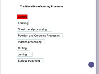
SRI RAMAKRISHNA INSTITUTE OF TECHNOLOGY,
COIMBATORE-10
AN AUTONOMOUS INSTITUTION
(APPROVED BY AICTE, NEW DELHI – AFFILIATED TO ANNA UNIVERSITY, CHENNAI)
MANUFACTURING PROCESSES- UMECOO2
I.Karthikeyan
Assistant Professor,
Mechanical Department .
6/10/2021
1
COURSE OBJECTIVES
 To introduce various forming processes available in
manufacturing products.
 To impart knowledge on various fabrication
techniques used in industries
SYLLABUS
METAL CASTING PROCESSES
Moulding sands - Types and Properties, Patterns -
types of patterns, selection of materials for patterns
- pattern allowances, Gating and Riser, Sand
moulding processes, Moulding machines, Core
requirements, Core making processes, Core
making machines, Permanent casting processes,
Melting furnaces, Casting defects and remedies
METAL FABRICATION PROCESSES
Classification of welding processes: Principle of
Gas welding, Arc welding, resistance welding, Solid
State Welding, Thermo chemical welding and
radiant energy welding – Welding defect and
remedies-Brazing and soldering.
METAL FORMING PROCESSES
Forging: Classification of forging processes,
Rolling: Classification of rolling processes - rolling
mill - rolling of bars and shapes. Extrusion:
Classification of extrusion processes - extrusion
equipments - examples. Drawing: Drawing of rods,
wires and tubes.
SHEET METAL AND POWDER METALLURGY
PROCESSES
Sheet metal forming methods: Shearing, Blanking,
Bending, Stretch Forming, deep forming. Spinning:
Spinning processes, High Velocity Forming. Powder
Metallurgy: Methods of producing powder.
Pressing, sintering, sizing-Advantages and
limitations
PLASTICS MANUFACTURING PROCESSES
Plastics Working: Types of plastics - plastic
moulding processes- Injection moulding -
Compression Moulding – Transfer Moulding –
Extrusion – Blow moulding – Thermoforming -
Rotational Moulding
LIST OF EXPERIMENTS:
 Preparation of Mould with solid patterns
 Preparation of Mould with split patterns
 Preparation of Mould with core
 Arc welding of two similar metals
 Sheet metal fabrication
REFERENCES
 Serope Kalpakjian , Steven Schmid , “Manufacturing
Engineering & Technology”, Pearson, Seventh Edition,
2014.
 M.P.Groover, “Fundamentals of Modern Manufacturing
Materials, Processes and Systems”, John Wiley & Sons,
2010.
 P N Rao, “Manufacturing Technology Volume 1:
Foundry, Forming and Welding”, Tata McGraw Hill,
Fourth Edition, 2013.
 Helmi A. Youssef, Hassan A. El-Hofy, Mahmoud H.
Ahmed, “Manufacturing Technology: Materials,
Processes, and Equipment”, CRC Press, 2011.s
 Nee, Andrew Yeh Ching (Ed), “Handbook of
Manufacturing Engineering and Technology”, Springer,
2015.
METAL CASTING PROCESSES
Moulding sands - Types and Properties, Patterns -
types of patterns, selection of materials for patterns
- pattern allowances, Gating and Riser, Sand
moulding processes, Moulding machines, Core
requirements, Core making processes, Core
making machines, Permanent casting processes,
Melting furnaces, Casting defects and remedies
1. WHAT IS MANUFACTURING ?
 Arrived from the Latin word “manu factus”, meaning
“made by hand”.
 Manufacturing is the process of converting raw
materials into products
 Manufacturing engineering or manufacturing
process are the steps through which raw materials are
transformed into a final product.
 The manufacturing process begins with the product
design, and materials specification from which the
product is made. These materials are then modified
through manufacturing processes to become the
required part.
WHY STUDY
MANUFACTURING PROCESSES?
The designer and the drafter must have a
working knowledge of the various processes that
could produce a part in order to: lower cost and
reduce production time.
THREE PHASES OF THE MANUFACTURING PROCESS
1. Product design.
2. Selection of materials.
3. Selection of production methods and techniques.
THE INFORMATION NEEDED TO PRODUCE A PART, MOST
OFTEN COMES IN THE FORM OF A: WORKING DRAWING
THREE MAIN STAGES OF THE PRODUCTION OF A
MACHINED PART
ROUGH FORMING
CASTING, FORGING, WELDING
FINISHING
DRILLING, MACHINING, SURFACING
ASSEMBLING
THE ASSEMBLY OF PARTS
CLASSIFICATION OF MANUFACTURING
PROCESSES
 Processing Operations
Shaping Processes- Powder Metallurgy, Forming
Processes, Material Removal /Machining
Processes
Surface Processes- Cleaning and Surface treatment,
Coating and Deposition processes
Processes affecting Changes in properties- Heat
treatments
 Assembly Operations
Permanent joining Operations- welding, brazing,
soldering
Mechanical fastening Processes- threaded fasteners,
rivets
CLASSIFICATION OF MANUFACTURING
PROCESSES
 (Metal) Casting Processes
 Joining Processes
 (Metal) Forming Processes
 Sheet metal Processes
 Plastic materials (Polymers) processes
 Machining processes
 Powder Metallurgy
 Heat treatment & Surface treatment processes
 Assembly processes
18
FACTS
 "ferrous" means generally "containing iron". The
word is derived from the Latin word ferrum
("iron"). Ferrous metals include steel and pig iron
(with a carbon content of a few percent) and alloys
of iron with other metals
 Carbon is the 15th most abundant element in the Earth's
crust, and the fourth most abundant element in the
universe by mass after hydrogen, helium, and oxygen.
Carbon's abundance, its unique diversity of organic
compounds, and its unusual ability to form polymers at
the temperatures commonly encountered
on Earth enables this element to serve as a common
element of all known life. It is the second most abundant
element in the human body by mass (about 18.5%) after
oxygen.
 is a chemical element with the symbol C and atomic
number 6. It is nonmetallic and tetravalent—making
four electrons available to form covalent chemical bonds
Traditional Manufacturing Processes
Casting
Forming
Sheet metal processing
Cutting
Joining
Powder- and Ceramics Processing
Plastics processing
Surface treatment

INTRODUCTION- METAL CASTING
 Casting is a process in which a liquid metal is
somehow delivered into a mold that contains a
hollow shape of the intended shape.
 The metal is poured into the mold through a hollow
channel called a sprue.
 The metal and mold are then cooled, and the metal
part (the casting) is extracted.
 Casting is most often used for making complex
shapes that would be difficult or uneconomical to
make by other methods
1.1 INTRODUCTION- METAL CASTING
Foundry
 A foundry is a factory that produces metal castings.
 Metals are cast into shapes by melting them into a
liquid, pouring the metal into a mold, and removing the
mold material after the metal has solidified as it cools.
 The most common metals processed
are aluminium and cast iron.
 However, other metals, such
as bronze, brass, steel, magnesium, and zinc, are also
used to produce castings in foundries. In this process,
parts of desired shapes and sizes can be formed.
EARLY HISTORY
 The oldest known cast
in existence is a
copper frog from 3200
BCE in Mesopotamia.
 Other early casts from
around 3000BCE like
weapons and cult
objects were
discovered in the
Middle East and India.
THE CASTING PROCESS
 The rough casting is now ready for the machine shop.
 Holes are then bored and reamed.
 Top and bottom surfaces are machined
 Smaller holes will be drilled and counterbored.
 All corners on cast parts are fillets and rounds.
Rough
Casting
Machined
Finish
 Casting processes have been known for thousands of
years,
 Traditional techniques include lost-wax casting (which
may be further divided into centrifugal
casting and vacuum assist direct pour casting), plaster
mold casting and sand casting.
 The modern casting process is subdivided into two
main categories: expendable and non-expendable
casting.
 It is further broken down by the mold material, such as
sand or metal, and pouring method, such as gravity,
vacuum, or low pressure
Casting
Refractory mold  pour liquid metal  solidify, remove  finish
• VERSATILE: complex geometry, internal cavities, hollow sections
• VERSATILE: small (~10 grams)  very large parts (~1000 Kg)
• ECONOMICAL: little wastage (extra metal is re-used)
• ISOTROPIC: cast parts have same properties along all directions
WHY WE USE CASTING
 Capable of large sizes
 Capable of holding detail
 Useful for metals with low
ductility
 Most economical type of
fabrication
 Minimal waste
 Empty spaces can weaken
metal
 Poor surface finish
 Small parts hard to remove
 Additional hardening usually
needed
Advantages Disadvantages
WHAT IS SAND CASTING?
 Sand Casting is a process in which a cast is formed from
a molten metal in a sand mold.
 Can be used to produce a range of sizes from a fraction of
an ounce to hundreds of tons.
 Sand casting, also known as sand molded casting, is
a metal casting process characterized by using sand as
the mold material.
 The term "sand casting" can also refer to an object
produced via the sand casting process.
 Sand castings are produced in
specialized factories called foundries. Over 60% of all
metal castings are produced via sand casting process.
 SAND CASTING
 Sand moulds
 Type of patterns
– Pattern materials
– Pattern allowances
 Moulding sand
– Types
– Properties
– Testing
 Core making
– Types
– Applications
 Moulding machines
– Types
– Application
 MELTING FURNACES
– Blast
– Cupola
 SPECIAL CASTING
PROCESSES
– Shell
– investment casting
– Ceramic mould
– Lost Wax process
– Pressure die casting
– Centrifugal casting
– CO2 process
– Stir Casting
(Working principle)
 DEFECTS IN SAND CASTING
36
37
STAGES IN SAND CASTING
There are six steps in this process:
 Place a pattern in sand to create a mold.
 Incorporate the pattern and sand in a gating
system.
 Remove the pattern.
 Fill the mold cavity with molten metal.
 Allow the metal to cool.
 Break away the sand mold and remove the casting.
MOLDING OR MOULDING
 It is the process of creating a cavity in a moulding
box, formed by a pattern.
 The cavity is similar in shape and size to that of the
actual casting plus some allowances provided on
the pattern. A mould is made of some sort of heat
resistant materials .
 Silica is the mostly used with binding materials
because of its abundance
 It is cheap and can be packed into any desired shape.
 It mainly does not react with molten metals and can
withstand high temperatures.
 Water, Clay, Molasses are used as binding materials in
different proportions.
Two types
 Permanent Mould
 Temporary Moulds
Permanent Moulds
 Generally used for casting low melting point materials
 Made of ferrous metals and alloys such as gray cast
iron and steels
 They are very costlier and are suited for large scale
production of small sized similar parts.
Temporary Moulds
These are made of refractory resins, sand, plaster of
Paris and ceramics etc.,
Suitable for only one casting and has to be produced
fresh each time using patterns.
Gating System
 It is nothing but the basic design, which is needed to
construct a smooth and proper filling of the mold
cavity of the casting without any discontinuity, voids or
solid inclusions.
 A proper method of gating system is that it leads the
pure molten metal to flow through a ladle to the
casting cavity, which ensures proper and smooth
filling of the cavity.
 This depends on the layout of the gating channels too,
such as the direction and the position of the runner,
sprue and ingates
 The main elements needed for the gating system are
as follows:
 Pouring basin or bush.
 Sprue or downspure.
 Sprue Well
 Runner
 Ingate
 Ladle
 Slag trap or filter.
 The characteristics of each element are mentioned
below:
 Pouring basin : This is otherwise called as bush or cup.
It is circular or rectangular in shape. It collects the molten
metal, which is poured, from the ladle.
 Sprue : It is circular in cross section. It leads the molten
metal from the pouring basin to the sprue well.
 Sprue Well : It changes the direction of flow of the
molten metal to right angle and passes it to the runner.
 Runner : The runner takes the molten metal from sprue
to the casting.
 Ingate: This is the final stage where the molten metal
moves from the runner to the mold cavity.
 Slag trap : It filters the slag when the molten metal
moves from the runner and ingate. It is also placed in the
runner.
 A riser, also known as a feeder, is a reservoir built
into a metal casting mold to prevent cavities due
to shrinkage.
 Most metals are less dense as a liquid than as a solid
so castings shrink upon cooling, which can leave a
void at the last point to solidify. Risers prevent this by
providing molten metal to the casting as it solidifies,
so that the cavity forms in the riser and not the
casting
GENERAL SAND CASTING
 Two-piece casting flask
 top is cope, bottom is
drag
 Sand packed around
pattern of intended shape
 Gating system for metal
flow and escape
 trimming necessary
 Often used with
automotive parts and
piping
 Iron, steel, bronze,
aluminum, lead, tin, zinc
ADVANCEMENTS IN SAND CASTING
 In 1924, the Ford automobile company set a record
production of 1 million cars, consuming the casting
industry.
 Experiments were conducted with types of clay to
improve strength in molding sand, updating cupola
furnaces to electric and moving the traditional
foundry to a factory setting improved process.
 Now, sand casting is a fully automated factory
system.
TYPES OF SAND
 Green sand , Dry sand , Loam Sand , facing sand
Backing sand, System Sand , Parting sand, Core
sand and Molasses Sand
Most common
 Silica sand, water, clay
 Named for moisture, not color
 Sand must maintain certain properties
 i.e. strength, thermal stability, collapsibility, reusability
 Compressed with hydraulic pressure
 Sometimes different layers of different qualities
GREEN SAND
 Green sand. Green sand is an aggregate of sand,
bentonite clay in silica sand, pulverized coal and 6 to
8%water. Its principal use is in making molds for
metal casting.
 The function of the clay and water is to provide the requisite
bond for green sand. It is fine, light, soft and powerful.
 It can be squeezed in hand to provide any shape.
 Moulds in this sand are known as green sand and do not
need any baking before pouring the molten metal in them.
The green sand is the natural sand containing sufficient
moisture in it.
 Used for producing simple, small and medium sized castings
DRY SAND
 When the moisture is removed from green sand, it
is known as dry sand. After evaporation of moisture
from the mould, the mould produced by dry sand
has greater strength, rigidity and thermal stability.
This sand is used for large and heavy castings.
LOAM SAND
 Loam sand is a mixture of 50 percent sand and 50
percent clay. Water is added in sufficient amount. It
is used for large and heavy moulds e.g., turbine
parts, hoppers etc
 It is used in the form of thin paste, the moulds are
formed with a backing of soft bricks . It contains fire
clay, graphite and fibrous reinforcement.
 Fire clay is a range of refractory clays used in the manufacture of ceramics, especially fire
brick. The United States Environmental Protection Agency defines fire clay very generally as a
"mineral aggregate composed of hydrous silicates of aluminium (Al2O3·2SiO2·2H2O) with or
without free silica
FACING SAND
 A sand used for facing of the mould is known as
facing sand.
 It consists of silica sand and clay, without addition
of used sand. It is used directly next to the surface
of the pattern.
 Facing sand comes in direct contact with the hot
molten metal; therefore it must have high
refractoriness and strength. It has very fine grains.
 Different forms of carbon known as facing materials
(graphite or plumbago powder) are used to prevent
the metal from burning into the sand.
BACKING SAND
 The backing sand is old and repeatedly used sand
of black colour. It is used to back up the facing sand
and to fill the whole volume of the box. This sand is
accumulated on the floor after casting and hence
also known as floor sand.
 Black in color due to the addition of coal dust and
burning after coming in contact with molten metal.
 It is weak in bonding strength and does not come in
contact with the pattern.
PARTING SAND
 A pure silica sand employed on the faces of the
pattern before moulding is known as parting sand.
When the pattern is withdrawn from the mould, the
moulding sand sticks to it.
 To avoid sticking, parting sand is sprinkled on the
pattern before it is embedded in the moulding sand.
Parting sand is also sprinkled on the contact
surface of cope, drag and cheek.
 Burnt core sand would be used for this purpose.
SYSTEM SAND
 The sand employed in mechanical heavy castings
and has high strength, permeability and
refractoriness, is known as system sand.
 It is used for machine moulding to fill the whole
flask. In machine moulding no facing sand is used.
The system sand is cleaned and has special
additives.
CORE SAND
 A sand used for making cores is known as core
sand. It is silica sand mixed with core oil (linseed
oil, resin, mineral oil) and other binding materials
(dextrine, corn flour, sodium silicate). It has
remarkable compressive strength.
MOLASSES SAND:
 A sand which carries molasses as a binder is
known as molasses sand. It is used for core making
and small castings of intricate shapes.
CHARACTERISTICS OF MOULDING SAND
Refractoriness is the property of sand to withstand
high temperature of molten metal without fusion or
soften and thus facilitating a clean casting
 Moulding sands with poor refractoriness may burn
when the molten metal is poured into the mould.
Usually, sand moulds should be able to withstand
up to 1650°C.
 Rough and larger grains possess higher
refractoriness.
 Chemicals like oxides of iron, sodium, potassioum
and calcium react chemically during pouring of
molten metal and hence to be avoided
Flow-ability is the ability of moulding sand to free flow
and fill the recesses and the fine details in the
pattern. It varies with moisture content.
It can also be stated as the ability of sand to beahve
like a fluid, so that it flows during ramming to all
portions of the moulding box .
Under pressure – flow, retain the shape when
pressure is removed.
POROSITY OR PERMEABILITY
 Porosity also known as permeability is the most
important property of the moulding sand.
 It is the ability of the moulding sand to allow gasses to
pass through. Gasses and steam are generated during
the pouring of molten metal into the sand cavity.
 This property depends not only on the shape and size
of the particles of the sand but also on the amount of
the clay, binding material, and moisture contents in the
mixture.
 This gases are those that are absorbed from the
atmosphere, steam formed due to heating of moisture,
coal dust , oil and other binders present in sand.
COHESIVENESS
 Cohesiveness is the property of sand to hold its
particles together. It may be defined as the strength
of the moulding sand. This property plays a vital
role in retaining intricate shapes of the mould.
 Insufficient strength may lead to a collapse in the
mould particles during handling, turning over, or
closing. Clay and bentonite improves the
cohesiveness.
ADHESIVENESS
 Adhesiveness is the property of sand due to which
the sand particles sticks to the sides of the
moulding box. Adhesiveness of sand enables the
proper lifting of cope along with the sand.
Plasticity
 Plasticity is the property of the moulding sand by
virtue of which it flows to all corners around the
mould when rammed, thus not providing any
possibility of left out spaces, andacquires a
predetermined shape under ramming pressure.
COLLAPSIBILITY:
 Collapsibility is the property of sand due to which
the sand mould collapse automatically after the
solidification of the casting. The mould should
disintegrate into small particles of moulding sand
with minimum force after the casting is removed
from it.
 GREEN STRENGTH, DRY STRENGTH, HOT
STRENGTH, FINENESS
TYPES OF SAND
1. Natural Sand
 Available from natural deposits
 Needs only 5-8% water
 Used for light castings in Ferrous & Non-Ferrous
2. Synthetic Sand
 Prepared (with desired properties, as we like) artificially by
mixing clay free sand
 Used in mechanized production machine moulding & High
pressure moulding.
3. Special Sand
a) Zircon sand
b) Chromite sand
68
MOULDING SAND
According to the amount of clayey matter they
contain, the moulding sands are classified as:
1. Silica Sand : Upto 2% clay
2. Lean or Weak sand : 2 to 10% clay
3. Moderately strong sand : 10 to 20% clay
4. Strong sand : Upto 30% clay
5. Extra strong sand : Upto 50% clay
Types of sand :
1. Natural 2. Synthetic 3. Chemically coated
69
DESIRABLE MOLD SAND PROPERTIES AND
CHARACTERISTICS
 Strength - to maintain shape and resist erosion
 Permeability - to allow hot air and gases to pass through
voids in sand
 Thermal stability - to resist cracking on contact with
molten metal
 Collapsibility - ability to give way and allow casting to
shrink without cracking the casting
 Reusability - can sand from broken mold be reused to
make other molds. 70
BINDERS
 Organic - Cereal, resins, pitch, drying oil, molasses
etc.,
 In-Organic - Fire clay, KAOLINITE, BENTONITE and
ILLITE
High Thermo Chemical stability
TYPICAL GREEN MOULDING SAND for gray iron
Silica sand = 68 to 86%
Clay = 10 to 20%
Water = 3 to 6%
Additives = 1 to 6%
71
ADDITIVES
Additives are added to the molding sand to
improve the properties like strength, refractoriness
and permeability.
Necessary of Additives:
1. To give a good surface finish to the casting
2. To eliminate casting defects
(Expansion of moulding sand or Contraction of he
casting)
72
1) Sea Coal – fine bituminous coal powder
2) Saw dust
3) Pitch – distilled from soft coal
4) Cereals – ground corn flour or corn starch
5) Silica flour – very fine powdered silica
6) Special additives
 Fuel oil
 Dextrin
 Molasses
 Iron oxide
73
Sand Casting
cope: top half
drag: bottom half
core: for internal cavities
pattern: positive
funnel  sprue 
 runners  gate 
 cavity 
 {risers, vents}
SOFTWARE SUPPORT
 Casting process simulation uses numerical methods to
calculate cast component quality considering mold filling,
solidification and cooling, and provides a quantitative
prediction of casting mechanical properties, thermal
stresses and distortion.
 Simulation accurately describes a cast component's quality
up-front before production starts.
 The casting rigging can be designed with respect to the
required component properties.
 This has benefits beyond a reduction in pre-production
sampling, as the precise layout of the complete casting
system also leads to energy, material, and tooling savings.
 Casting process simulation was initially developed at
universities starting from the early '70s, mainly in Europe
and in the U.S., and is regarded as the most important
innovation in casting technology over the last 50 years.
 Since the late '80s, commercial programs (such
as AutoCAST and MAGMA) are available which make it
possible for foundries to gain new insight into what is
happening inside the mold or die during the casting process
PATTERN
 Primarily used to produce the mould cavity in sand.
 It is slightly larger than the desired casting, due to
various allowances.
 It is the principal tool used in casting process
 The model or replica of the object to be cast
 Used for forming an impression known as mold in
damp sand or other suitable molding material.
 This mold is a cavity, which when filled with molten
metal that is allowed to solidy, forms a reproduction
of the pattern called casting.
77
 Since it is a direct duplication, the patter very closely
confirms to the shape and size of the desired casting
except for a few variations due to the essential
allowances provided in the pattern.
 The process of making patterns is known as pattern
making.
TYPES OF PATTERN
1. Single piece pattern.
2. Split piece pattern.
3. Loose piece pattern.
4. Match plate pattern.
5. Sweep pattern.
6. Gated pattern.
7. Skeleton pattern
8. Follow board pattern.
9. Cope and Drag pattern.
79
1. SINGLE PIECE (SOLID) PATTERN
 Made from one piece and does not contain loose pieces or joints.
 Inexpensive.
 Used for large size simple castings.
 Pattern is accommodated either in the cope or in the drag.
Examples:
1. Bodies of regular shapes.
2. stuffling box of steam engine.
80
 This pattern is the cheapest one but its use is to
limited extent for production as the moulder has to
cut his own runners, risers and feeding gates.
SINGLE PIECE PATTERN
82
2. SPLIT PIECE PATTERN:
 Patterns of intricate shaped castings cannot be made in one
piece because of the inherent difficulties associated with the
molding operations (e.g. withdrawing pattern from mould).
 The upper and the lower parts of the split piece patterns are
accommodated in the cope and drag portions of the mold
respectively.
 Parting line of the pattern forms the parting line of the mould.
83
 Dowel pins are used for keeping the alignment between
the two parts of the pattern.
 Examples:
1. Hallow cylinder
2. Taps and water
stop cocks etc.,
84
85
86
3.LOOSE PIECE PATTERN
 Certain patterns cannot be withdrawn once they are embedded in
the molding sand. Such patterns are usually made with one or more
loose pieces for facilitating from the molding box and are known as
loose piece patterns.
 Loose parts or pieces remain attached with the main body of the
pattern, with the help of dowel pins.
 The main body of the pattern is drawn first from the molding box
and thereafter as soon as the loose parts are removed, the result is
the mold cavity.
87
88
4. MATCH PLATE PATTERN
 It consists of a match plate, on either side of which each
half of split patterns is fastened.
 A no. of different sized and shaped patterns may be
mounted on one match plate.
 The match plate with the help of locator holes can be
clamped with the drag.
 After the cope and drag have been rammed with the
molding sand, the match plate pattern is removed from in
between the cope and drag.
89
 Small and accurate castings- rapid production
 Aluminium is used as metal plate
 Greater dimensional accuracy and minimum requirement
for machining of the castings
 It consists of a flat metal plate or wooden plate to which
the patterns and gates are permanently fastened
 Match plate patterns are normally used in machine molding.
 By using this we can eliminate mismatch of cope and drag
cavities.
91
5. SWEEP PATTERN
 A sweep pattern is just a form made on a wooden
board which sweeps the shape of the casting into the
sand all around the circumference. The sweep
pattern rotates about the post.
 Once the mold is ready, Sweep pattern and the post
can be removed.
 Sweep pattern avoids the necessity of making a full,
large circular and costly three-dimensional pattern.
92
 Making a sweep pattern saves a lot of time and labor as
compared to making a full pattern.
 A sweep pattern is preferred for producing large casting of
circular sections and symmetrical shapes.
 Used to produce symmetrically large castings, particularly of
round cross sections, the outer edge of
93
94
6. GATED PATTERN
 The sections connecting different patterns serve as runner
and gates.
 This facilitates filling of the mould with molten metal in a
better manner and at the same time eliminates the time and
labour otherwise consumed in cutting runners and gates.
 A gated pattern can manufacture many casting at one time
and thus it is used in mass production systems.
 Gated patterns are employed for producing small castings.
95
96
 Provision for easy passage of the flowing molten metal
into the mould is known as gating.
 Gated patterns are used in mass production of small
castings.
 The time normally spent by the moulder in creation of
the gates and withdrawal of patterns is eliminated by
this arrangement.
7. SKELETON PATTERN
 A skeleton pattern is the skeleton of a desired shape
which may be S-bend pipe or a chute or something
else. The skeleton frame is mounted on a metal base
 The skeleton is made from wooden strips, and is
thus a wooden work.
 The skeleton pattern is filled with sand and is
rammed.
98
 A strickle (board) assists in giving the desired shape to the sand
and removes extra sand.
 Skeleton patterns are employed for producing a few large
castings.
 A skeleton pattern is very economical, because it involves less
material costs.
99
8. FOLLOW BOARD PATTERN
 A follow board is a wooden board and is used for supporting a
pattern which is very thin and fragile and which may give way
and collapse under pressure when the sand above the pattern is
being rammed.
 With the follow board support under the weak pattern, the drag
is rammed, and then the fallow board is with drawn, The
rammed drag is inverted, cope is mounted on it and rammed.
100
 During this operation pattern remains over the inverted drag
and get support from the rammed sand of the drag under it.
 Follow boards are also used for casting master patterns for
many applications.
101
102
9. COPE AND DRAG PATTERNS
 A cope and drag pattern is another form of split pattern.
 Each half of the pattern is fixed to a separate metal/wood
plate.
 Each half of the pattern(along the plate) is molded
separately in a separate molding box by an independent
molder or moulders.
103
 The two moulds of each half of the pattern are finally
assembled and the mould is ready for pouring.
 Cope and drag patterns are used for producing big castings
which as a whole cannot be conveniently handled by one
moulder alone.
104
COPE AND DRAG PATTERN
105
(A)SPLIT
PATTERN
(B) FOLLOW-
BOARD
(C) MATCH
PLATE
(D) LOOSE-PIECE
(E) SWEEP
(F) SKELETON
PATTERN
106
(a) solid pattern
(b) split pattern
(c) match-plate pattern
(d) cope and drag pattern 107
PATTERN MATERIALS
1. Wood – Teak, Mahogany, White pine….
2. Metal – Cast Iron, Brass, Aluminium, White metal
3. Plaster
4. Plastics
5. Wax
108
COLOUR SCHEME FOR PATTERNS
1. Surface as cast : BLACK
2. Machined surface : RED
3. Core prints an seats : YELLOW
4. Loose pieces : YELLOW / RED
(diagonal stripes)
5. Stop-off : YELLOW / BLACK
(diagonal stripes)
109
SELECTION OF PATTERN
MATERIALS
(REQUIREMENTS OF A GOOD PATTERN)
 Secure the desired shape and size of the casting.
 Cheap and readily repairable.
 Simple in design for ease of manufacture.
 Light in mass and convenient to handle.
 Have high strength and long life in order to make as
many moulds as required.
 Retain its dimensions and rigidity during the definite
service life.
110
PATTERN ALLOWANCE
The difference in the dimensions of the casting and
the pattern is due to the various allowances considered
while designing a pattern for a casting.
The various types of allowances are,
111
SHRINKAGE ALLOWANCE
MACHINING or FINISH
ALLOWANCE
112
DRAFT or TAPER
ALLOWANCE DISTORTION or CAMBER
ALLOWANCE
113
RAPPING OR SHAKE ALLOWANCE
 To remove the pattern out of mould cavity, it is
slightly rapped or shaked to detach it from the
mould cavity.
 Negative Allowance – subtracted from pattern
dimensions.
114
MOULDING SAND PREPARATION
 Mixing of sand
 Tempering of sand
 Conditioning of sand
115
MOULDING TOOLS
116
117
118
CORE
A Core is a body made of sand which is used to
make a cavity or a hole in a casting.
 Core Print is the projection on a pattern.
 It forms a seat in the mould.
 Core is supported in the seat formed by the
Core Print.
119
TYPES OF CORE
a) According to the state of core
i. Green sand core
ii. Dry sand core
b) According to the position of the core in the
mould
i. Horizontal core
ii. Vertical core
iii. Balanced core
iv. Hanging core
v. Drop core
120
121
ESSENTIAL QUALITIES OF A CORE:
1. Permeability
2. Refractoriness
3. Strength
4. Collapsibility
5. Stability
MATERIALS:
 Core Sand (Refractories) – Silica sand, Zircon,
Olivin etc.,
 Binders – Vegetable or Mineral oil, Corn flour,
Resins water, Fire clay, Bentonite, Urea
 Additives – Wood flour, Coal powder, Seal coal,
Graphite, Cow dung, Straw etc.,
122
CORE BOXES
1. Half core box
2. Dump or slap core box
3. Split core box
123
4. Strickle core box
5. Gang core box
124
CORE OVENS
1. Batch type ovens
2. Continuous type ovens
125
3. Dielectric baking ovens
126
CORE MAKING METHOD
1. Hand core making
i. Core sand preparation
ii. Moulding a green sand core
iii. Baking - 200oC to 350oC
iv. Finishing
a. Trimming – removing fins and sand projections by filing
b. Brushing – process of removing loose sand by brushes
c. Sizing – making a core to a correct size by grinding or filing
v. Coating
 Coating material – powdered graphite or Silica or Mica
 Coating is applied either by dipping or spraying. This is also called
as Dressing
127
2. Hot core box method
128
 Baking or Curing will be lengthens the
production process and lowers the operating
efficiency of the foundry.
 This can be eliminated by using quickset
synthetic resins-bonded core sands.
 Binders – Phenol formaldehyde, Urea
formaldehyde, Phenolic alcohols and Furan-base
binders.
 These binders are capable of hardening at 230-250oC
in a short time (2 to 3 minutes)
 Catalysts – Benzene sulfonic and Nitric acids (to speed up the
process of curing)
129
3. Synthetic resin-based cold curing Method
 These sands do not require heat treatment after obtaining
from ovens.
In this method core is allowed to stand in the air for
30 to 120 min. (having strength of about 800 to 1200 kPa.
 Strength is lesser than HOT BOX METHOD.
 Only used for moderately complex and simple configuration.
130
(MOULDING) SAND TESTING METHODS
1. Moisture content test
2. Clay content test
3. Grain fitness test
4. Permeability test
5. Strength test
6. Deformation or Toughness test
7. Hot strength test
8. Refractoriness test
9. Mould hardness test
131
(CORE) SAND TESTING METHODS
1. Green strength test
2. Baked strength test
3. Retained strength test
4. Core strength test
5. Moisture content test
132
SPECIAL CASTING PROCESSES
1. Shell Mould Casting
2. Investment Casting
3. Ceramic Mould Casting
4. Lost Wax Process
133
5. Pressure Die Casting
1) Hot chamber Die Casting
2) Cold chamber Die Casting
6. Gravity Die Casting
7. Centrifugal Casting
8. Continuous Casting process
134
Different Casting Processes
Process Advantages Disadvantages Examples
Sand many metals, sizes, shapes, cheap poor finish & tolerance engine blocks,
cylinder heads
Shell mold better accuracy, finish, higher
production rate
limited part size connecting rods, gear
housings
Expendable
pattern
Wide range of metals, sizes,
shapes
patterns have low
strength
cylinder heads, brake
components
Plaster mold complex shapes, good surface
finish
non-ferrous metals, low
production rate
prototypes of
mechanical parts
Ceramic mold complex shapes, high accuracy,
good finish
small sizes impellers, injection
mold tooling
Investment complex shapes, excellent finish small parts, expensive jewellery
Permanent
mold
good finish, low porosity, high
production rate
Costly mold, simpler
shapes only
gears, gear housings
Die Excellent dimensional accuracy,
high production rate
costly dies, small parts,
non-ferrous metals
gears, camera bodies,
car wheels
Centrifugal Large cylindrical parts, good
quality
Expensive, few shapes pipes, boilers,
flywheels
SHELL MOULD CASTING
136
 5 to 10% - Phenolic resin mixed with fine dry silica
(Mixer – dry oil or presence of alcohol)
 No water
 230 – 600◦C
 Release Agent – Silicone (sprayed over pattern)
 Thickness of shell – time of contact of the mixture
with the heated pattern (Ex: 20-30 sec, 6 mm)
 Then the mould is heated in an Oven at 300◦C for
15-60 sec.
 After cooling &Solidification, the shells are broken or
shaken away from the castings.
 Brake drums, Bushings, Cams, Cam shaft, rollers
etc.,
137
INVESTMENT CASTING
138
139
PRESSURE DIE CASTING
PDC - HOT CHAMBER
140
PDC - COLD CHAMBER
141
GRAVITY DIE CASTING
(PERMANENT MOLD CASTING)
142
CENTRIFUGAL CASTING
143
CONTINUOUS CASTING PROCESS
144
OTHER CASTING METHODS
 LOST WAX PROCESS
 CERAMIC MOULD CASTING
145
DEFECTS
1. Shrinkage
2. Blow holes
3. Scab
4. Swell
5. Hard Spots
6. Run out
7. Honey combing
8. Cracks
9. Shift
10. Cold Shut
11. Inclusions
12. Fins
13. Dress
14. Rat tail
15. Blister 146
INSPECTION METHODS
1. Visual Inspection
2. Pressure Test
3. Magnetic Particle Inspection
4. Dye-Penetrant Inspection
5. Radiographic Inspection
6. Ultrasonic Inspection
7. Thermography Inspection
147

Manufacturing Technology I

  • 1.
    SRI RAMAKRISHNA INSTITUTEOF TECHNOLOGY, COIMBATORE-10 AN AUTONOMOUS INSTITUTION (APPROVED BY AICTE, NEW DELHI – AFFILIATED TO ANNA UNIVERSITY, CHENNAI) MANUFACTURING PROCESSES- UMECOO2 I.Karthikeyan Assistant Professor, Mechanical Department . 6/10/2021 1
  • 2.
    COURSE OBJECTIVES  Tointroduce various forming processes available in manufacturing products.  To impart knowledge on various fabrication techniques used in industries
  • 3.
  • 4.
    METAL CASTING PROCESSES Mouldingsands - Types and Properties, Patterns - types of patterns, selection of materials for patterns - pattern allowances, Gating and Riser, Sand moulding processes, Moulding machines, Core requirements, Core making processes, Core making machines, Permanent casting processes, Melting furnaces, Casting defects and remedies
  • 5.
    METAL FABRICATION PROCESSES Classificationof welding processes: Principle of Gas welding, Arc welding, resistance welding, Solid State Welding, Thermo chemical welding and radiant energy welding – Welding defect and remedies-Brazing and soldering.
  • 6.
    METAL FORMING PROCESSES Forging:Classification of forging processes, Rolling: Classification of rolling processes - rolling mill - rolling of bars and shapes. Extrusion: Classification of extrusion processes - extrusion equipments - examples. Drawing: Drawing of rods, wires and tubes.
  • 7.
    SHEET METAL ANDPOWDER METALLURGY PROCESSES Sheet metal forming methods: Shearing, Blanking, Bending, Stretch Forming, deep forming. Spinning: Spinning processes, High Velocity Forming. Powder Metallurgy: Methods of producing powder. Pressing, sintering, sizing-Advantages and limitations
  • 8.
    PLASTICS MANUFACTURING PROCESSES PlasticsWorking: Types of plastics - plastic moulding processes- Injection moulding - Compression Moulding – Transfer Moulding – Extrusion – Blow moulding – Thermoforming - Rotational Moulding
  • 9.
    LIST OF EXPERIMENTS: Preparation of Mould with solid patterns  Preparation of Mould with split patterns  Preparation of Mould with core  Arc welding of two similar metals  Sheet metal fabrication
  • 10.
    REFERENCES  Serope Kalpakjian, Steven Schmid , “Manufacturing Engineering & Technology”, Pearson, Seventh Edition, 2014.  M.P.Groover, “Fundamentals of Modern Manufacturing Materials, Processes and Systems”, John Wiley & Sons, 2010.  P N Rao, “Manufacturing Technology Volume 1: Foundry, Forming and Welding”, Tata McGraw Hill, Fourth Edition, 2013.  Helmi A. Youssef, Hassan A. El-Hofy, Mahmoud H. Ahmed, “Manufacturing Technology: Materials, Processes, and Equipment”, CRC Press, 2011.s  Nee, Andrew Yeh Ching (Ed), “Handbook of Manufacturing Engineering and Technology”, Springer, 2015.
  • 11.
    METAL CASTING PROCESSES Mouldingsands - Types and Properties, Patterns - types of patterns, selection of materials for patterns - pattern allowances, Gating and Riser, Sand moulding processes, Moulding machines, Core requirements, Core making processes, Core making machines, Permanent casting processes, Melting furnaces, Casting defects and remedies
  • 12.
    1. WHAT ISMANUFACTURING ?  Arrived from the Latin word “manu factus”, meaning “made by hand”.  Manufacturing is the process of converting raw materials into products  Manufacturing engineering or manufacturing process are the steps through which raw materials are transformed into a final product.  The manufacturing process begins with the product design, and materials specification from which the product is made. These materials are then modified through manufacturing processes to become the required part.
  • 13.
    WHY STUDY MANUFACTURING PROCESSES? Thedesigner and the drafter must have a working knowledge of the various processes that could produce a part in order to: lower cost and reduce production time.
  • 14.
    THREE PHASES OFTHE MANUFACTURING PROCESS 1. Product design. 2. Selection of materials. 3. Selection of production methods and techniques.
  • 15.
    THE INFORMATION NEEDEDTO PRODUCE A PART, MOST OFTEN COMES IN THE FORM OF A: WORKING DRAWING
  • 16.
    THREE MAIN STAGESOF THE PRODUCTION OF A MACHINED PART ROUGH FORMING CASTING, FORGING, WELDING FINISHING DRILLING, MACHINING, SURFACING ASSEMBLING THE ASSEMBLY OF PARTS
  • 17.
    CLASSIFICATION OF MANUFACTURING PROCESSES Processing Operations Shaping Processes- Powder Metallurgy, Forming Processes, Material Removal /Machining Processes Surface Processes- Cleaning and Surface treatment, Coating and Deposition processes Processes affecting Changes in properties- Heat treatments  Assembly Operations Permanent joining Operations- welding, brazing, soldering Mechanical fastening Processes- threaded fasteners, rivets
  • 18.
    CLASSIFICATION OF MANUFACTURING PROCESSES (Metal) Casting Processes  Joining Processes  (Metal) Forming Processes  Sheet metal Processes  Plastic materials (Polymers) processes  Machining processes  Powder Metallurgy  Heat treatment & Surface treatment processes  Assembly processes 18
  • 19.
    FACTS  "ferrous" meansgenerally "containing iron". The word is derived from the Latin word ferrum ("iron"). Ferrous metals include steel and pig iron (with a carbon content of a few percent) and alloys of iron with other metals
  • 20.
     Carbon isthe 15th most abundant element in the Earth's crust, and the fourth most abundant element in the universe by mass after hydrogen, helium, and oxygen. Carbon's abundance, its unique diversity of organic compounds, and its unusual ability to form polymers at the temperatures commonly encountered on Earth enables this element to serve as a common element of all known life. It is the second most abundant element in the human body by mass (about 18.5%) after oxygen.  is a chemical element with the symbol C and atomic number 6. It is nonmetallic and tetravalent—making four electrons available to form covalent chemical bonds
  • 24.
    Traditional Manufacturing Processes Casting Forming Sheetmetal processing Cutting Joining Powder- and Ceramics Processing Plastics processing Surface treatment
  • 25.
  • 27.
    INTRODUCTION- METAL CASTING Casting is a process in which a liquid metal is somehow delivered into a mold that contains a hollow shape of the intended shape.  The metal is poured into the mold through a hollow channel called a sprue.  The metal and mold are then cooled, and the metal part (the casting) is extracted.  Casting is most often used for making complex shapes that would be difficult or uneconomical to make by other methods
  • 28.
    1.1 INTRODUCTION- METALCASTING Foundry  A foundry is a factory that produces metal castings.  Metals are cast into shapes by melting them into a liquid, pouring the metal into a mold, and removing the mold material after the metal has solidified as it cools.  The most common metals processed are aluminium and cast iron.  However, other metals, such as bronze, brass, steel, magnesium, and zinc, are also used to produce castings in foundries. In this process, parts of desired shapes and sizes can be formed.
  • 29.
    EARLY HISTORY  Theoldest known cast in existence is a copper frog from 3200 BCE in Mesopotamia.  Other early casts from around 3000BCE like weapons and cult objects were discovered in the Middle East and India.
  • 30.
    THE CASTING PROCESS The rough casting is now ready for the machine shop.  Holes are then bored and reamed.  Top and bottom surfaces are machined  Smaller holes will be drilled and counterbored.  All corners on cast parts are fillets and rounds. Rough Casting Machined Finish
  • 31.
     Casting processeshave been known for thousands of years,  Traditional techniques include lost-wax casting (which may be further divided into centrifugal casting and vacuum assist direct pour casting), plaster mold casting and sand casting.  The modern casting process is subdivided into two main categories: expendable and non-expendable casting.  It is further broken down by the mold material, such as sand or metal, and pouring method, such as gravity, vacuum, or low pressure
  • 33.
    Casting Refractory mold pour liquid metal  solidify, remove  finish • VERSATILE: complex geometry, internal cavities, hollow sections • VERSATILE: small (~10 grams)  very large parts (~1000 Kg) • ECONOMICAL: little wastage (extra metal is re-used) • ISOTROPIC: cast parts have same properties along all directions
  • 34.
    WHY WE USECASTING  Capable of large sizes  Capable of holding detail  Useful for metals with low ductility  Most economical type of fabrication  Minimal waste  Empty spaces can weaken metal  Poor surface finish  Small parts hard to remove  Additional hardening usually needed Advantages Disadvantages
  • 35.
    WHAT IS SANDCASTING?  Sand Casting is a process in which a cast is formed from a molten metal in a sand mold.  Can be used to produce a range of sizes from a fraction of an ounce to hundreds of tons.  Sand casting, also known as sand molded casting, is a metal casting process characterized by using sand as the mold material.  The term "sand casting" can also refer to an object produced via the sand casting process.  Sand castings are produced in specialized factories called foundries. Over 60% of all metal castings are produced via sand casting process.
  • 36.
     SAND CASTING Sand moulds  Type of patterns – Pattern materials – Pattern allowances  Moulding sand – Types – Properties – Testing  Core making – Types – Applications  Moulding machines – Types – Application  MELTING FURNACES – Blast – Cupola  SPECIAL CASTING PROCESSES – Shell – investment casting – Ceramic mould – Lost Wax process – Pressure die casting – Centrifugal casting – CO2 process – Stir Casting (Working principle)  DEFECTS IN SAND CASTING 36
  • 37.
  • 38.
    STAGES IN SANDCASTING There are six steps in this process:  Place a pattern in sand to create a mold.  Incorporate the pattern and sand in a gating system.  Remove the pattern.  Fill the mold cavity with molten metal.  Allow the metal to cool.  Break away the sand mold and remove the casting.
  • 39.
    MOLDING OR MOULDING It is the process of creating a cavity in a moulding box, formed by a pattern.  The cavity is similar in shape and size to that of the actual casting plus some allowances provided on the pattern. A mould is made of some sort of heat resistant materials .  Silica is the mostly used with binding materials because of its abundance
  • 40.
     It ischeap and can be packed into any desired shape.  It mainly does not react with molten metals and can withstand high temperatures.  Water, Clay, Molasses are used as binding materials in different proportions. Two types  Permanent Mould  Temporary Moulds
  • 41.
    Permanent Moulds  Generallyused for casting low melting point materials  Made of ferrous metals and alloys such as gray cast iron and steels  They are very costlier and are suited for large scale production of small sized similar parts. Temporary Moulds These are made of refractory resins, sand, plaster of Paris and ceramics etc., Suitable for only one casting and has to be produced fresh each time using patterns.
  • 44.
    Gating System  Itis nothing but the basic design, which is needed to construct a smooth and proper filling of the mold cavity of the casting without any discontinuity, voids or solid inclusions.  A proper method of gating system is that it leads the pure molten metal to flow through a ladle to the casting cavity, which ensures proper and smooth filling of the cavity.  This depends on the layout of the gating channels too, such as the direction and the position of the runner, sprue and ingates
  • 45.
     The mainelements needed for the gating system are as follows:  Pouring basin or bush.  Sprue or downspure.  Sprue Well  Runner  Ingate  Ladle  Slag trap or filter.
  • 46.
     The characteristicsof each element are mentioned below:  Pouring basin : This is otherwise called as bush or cup. It is circular or rectangular in shape. It collects the molten metal, which is poured, from the ladle.  Sprue : It is circular in cross section. It leads the molten metal from the pouring basin to the sprue well.  Sprue Well : It changes the direction of flow of the molten metal to right angle and passes it to the runner.  Runner : The runner takes the molten metal from sprue to the casting.  Ingate: This is the final stage where the molten metal moves from the runner to the mold cavity.  Slag trap : It filters the slag when the molten metal moves from the runner and ingate. It is also placed in the runner.
  • 47.
     A riser,also known as a feeder, is a reservoir built into a metal casting mold to prevent cavities due to shrinkage.  Most metals are less dense as a liquid than as a solid so castings shrink upon cooling, which can leave a void at the last point to solidify. Risers prevent this by providing molten metal to the casting as it solidifies, so that the cavity forms in the riser and not the casting
  • 48.
    GENERAL SAND CASTING Two-piece casting flask  top is cope, bottom is drag  Sand packed around pattern of intended shape  Gating system for metal flow and escape  trimming necessary  Often used with automotive parts and piping  Iron, steel, bronze, aluminum, lead, tin, zinc
  • 51.
    ADVANCEMENTS IN SANDCASTING  In 1924, the Ford automobile company set a record production of 1 million cars, consuming the casting industry.  Experiments were conducted with types of clay to improve strength in molding sand, updating cupola furnaces to electric and moving the traditional foundry to a factory setting improved process.  Now, sand casting is a fully automated factory system.
  • 52.
    TYPES OF SAND Green sand , Dry sand , Loam Sand , facing sand Backing sand, System Sand , Parting sand, Core sand and Molasses Sand Most common  Silica sand, water, clay  Named for moisture, not color  Sand must maintain certain properties  i.e. strength, thermal stability, collapsibility, reusability  Compressed with hydraulic pressure  Sometimes different layers of different qualities
  • 53.
    GREEN SAND  Greensand. Green sand is an aggregate of sand, bentonite clay in silica sand, pulverized coal and 6 to 8%water. Its principal use is in making molds for metal casting.  The function of the clay and water is to provide the requisite bond for green sand. It is fine, light, soft and powerful.  It can be squeezed in hand to provide any shape.  Moulds in this sand are known as green sand and do not need any baking before pouring the molten metal in them. The green sand is the natural sand containing sufficient moisture in it.  Used for producing simple, small and medium sized castings
  • 54.
    DRY SAND  Whenthe moisture is removed from green sand, it is known as dry sand. After evaporation of moisture from the mould, the mould produced by dry sand has greater strength, rigidity and thermal stability. This sand is used for large and heavy castings.
  • 55.
    LOAM SAND  Loamsand is a mixture of 50 percent sand and 50 percent clay. Water is added in sufficient amount. It is used for large and heavy moulds e.g., turbine parts, hoppers etc  It is used in the form of thin paste, the moulds are formed with a backing of soft bricks . It contains fire clay, graphite and fibrous reinforcement.  Fire clay is a range of refractory clays used in the manufacture of ceramics, especially fire brick. The United States Environmental Protection Agency defines fire clay very generally as a "mineral aggregate composed of hydrous silicates of aluminium (Al2O3·2SiO2·2H2O) with or without free silica
  • 56.
    FACING SAND  Asand used for facing of the mould is known as facing sand.  It consists of silica sand and clay, without addition of used sand. It is used directly next to the surface of the pattern.  Facing sand comes in direct contact with the hot molten metal; therefore it must have high refractoriness and strength. It has very fine grains.  Different forms of carbon known as facing materials (graphite or plumbago powder) are used to prevent the metal from burning into the sand.
  • 57.
    BACKING SAND  Thebacking sand is old and repeatedly used sand of black colour. It is used to back up the facing sand and to fill the whole volume of the box. This sand is accumulated on the floor after casting and hence also known as floor sand.  Black in color due to the addition of coal dust and burning after coming in contact with molten metal.  It is weak in bonding strength and does not come in contact with the pattern.
  • 58.
    PARTING SAND  Apure silica sand employed on the faces of the pattern before moulding is known as parting sand. When the pattern is withdrawn from the mould, the moulding sand sticks to it.  To avoid sticking, parting sand is sprinkled on the pattern before it is embedded in the moulding sand. Parting sand is also sprinkled on the contact surface of cope, drag and cheek.  Burnt core sand would be used for this purpose.
  • 59.
    SYSTEM SAND  Thesand employed in mechanical heavy castings and has high strength, permeability and refractoriness, is known as system sand.  It is used for machine moulding to fill the whole flask. In machine moulding no facing sand is used. The system sand is cleaned and has special additives.
  • 60.
    CORE SAND  Asand used for making cores is known as core sand. It is silica sand mixed with core oil (linseed oil, resin, mineral oil) and other binding materials (dextrine, corn flour, sodium silicate). It has remarkable compressive strength.
  • 61.
    MOLASSES SAND:  Asand which carries molasses as a binder is known as molasses sand. It is used for core making and small castings of intricate shapes.
  • 62.
    CHARACTERISTICS OF MOULDINGSAND Refractoriness is the property of sand to withstand high temperature of molten metal without fusion or soften and thus facilitating a clean casting  Moulding sands with poor refractoriness may burn when the molten metal is poured into the mould. Usually, sand moulds should be able to withstand up to 1650°C.  Rough and larger grains possess higher refractoriness.  Chemicals like oxides of iron, sodium, potassioum and calcium react chemically during pouring of molten metal and hence to be avoided
  • 63.
    Flow-ability is theability of moulding sand to free flow and fill the recesses and the fine details in the pattern. It varies with moisture content. It can also be stated as the ability of sand to beahve like a fluid, so that it flows during ramming to all portions of the moulding box . Under pressure – flow, retain the shape when pressure is removed.
  • 64.
    POROSITY OR PERMEABILITY Porosity also known as permeability is the most important property of the moulding sand.  It is the ability of the moulding sand to allow gasses to pass through. Gasses and steam are generated during the pouring of molten metal into the sand cavity.  This property depends not only on the shape and size of the particles of the sand but also on the amount of the clay, binding material, and moisture contents in the mixture.  This gases are those that are absorbed from the atmosphere, steam formed due to heating of moisture, coal dust , oil and other binders present in sand.
  • 65.
    COHESIVENESS  Cohesiveness isthe property of sand to hold its particles together. It may be defined as the strength of the moulding sand. This property plays a vital role in retaining intricate shapes of the mould.  Insufficient strength may lead to a collapse in the mould particles during handling, turning over, or closing. Clay and bentonite improves the cohesiveness.
  • 66.
    ADHESIVENESS  Adhesiveness isthe property of sand due to which the sand particles sticks to the sides of the moulding box. Adhesiveness of sand enables the proper lifting of cope along with the sand. Plasticity  Plasticity is the property of the moulding sand by virtue of which it flows to all corners around the mould when rammed, thus not providing any possibility of left out spaces, andacquires a predetermined shape under ramming pressure.
  • 67.
    COLLAPSIBILITY:  Collapsibility isthe property of sand due to which the sand mould collapse automatically after the solidification of the casting. The mould should disintegrate into small particles of moulding sand with minimum force after the casting is removed from it.  GREEN STRENGTH, DRY STRENGTH, HOT STRENGTH, FINENESS
  • 68.
    TYPES OF SAND 1.Natural Sand  Available from natural deposits  Needs only 5-8% water  Used for light castings in Ferrous & Non-Ferrous 2. Synthetic Sand  Prepared (with desired properties, as we like) artificially by mixing clay free sand  Used in mechanized production machine moulding & High pressure moulding. 3. Special Sand a) Zircon sand b) Chromite sand 68
  • 69.
    MOULDING SAND According tothe amount of clayey matter they contain, the moulding sands are classified as: 1. Silica Sand : Upto 2% clay 2. Lean or Weak sand : 2 to 10% clay 3. Moderately strong sand : 10 to 20% clay 4. Strong sand : Upto 30% clay 5. Extra strong sand : Upto 50% clay Types of sand : 1. Natural 2. Synthetic 3. Chemically coated 69
  • 70.
    DESIRABLE MOLD SANDPROPERTIES AND CHARACTERISTICS  Strength - to maintain shape and resist erosion  Permeability - to allow hot air and gases to pass through voids in sand  Thermal stability - to resist cracking on contact with molten metal  Collapsibility - ability to give way and allow casting to shrink without cracking the casting  Reusability - can sand from broken mold be reused to make other molds. 70
  • 71.
    BINDERS  Organic -Cereal, resins, pitch, drying oil, molasses etc.,  In-Organic - Fire clay, KAOLINITE, BENTONITE and ILLITE High Thermo Chemical stability TYPICAL GREEN MOULDING SAND for gray iron Silica sand = 68 to 86% Clay = 10 to 20% Water = 3 to 6% Additives = 1 to 6% 71
  • 72.
    ADDITIVES Additives are addedto the molding sand to improve the properties like strength, refractoriness and permeability. Necessary of Additives: 1. To give a good surface finish to the casting 2. To eliminate casting defects (Expansion of moulding sand or Contraction of he casting) 72
  • 73.
    1) Sea Coal– fine bituminous coal powder 2) Saw dust 3) Pitch – distilled from soft coal 4) Cereals – ground corn flour or corn starch 5) Silica flour – very fine powdered silica 6) Special additives  Fuel oil  Dextrin  Molasses  Iron oxide 73
  • 74.
    Sand Casting cope: tophalf drag: bottom half core: for internal cavities pattern: positive funnel  sprue   runners  gate   cavity   {risers, vents}
  • 75.
    SOFTWARE SUPPORT  Castingprocess simulation uses numerical methods to calculate cast component quality considering mold filling, solidification and cooling, and provides a quantitative prediction of casting mechanical properties, thermal stresses and distortion.  Simulation accurately describes a cast component's quality up-front before production starts.  The casting rigging can be designed with respect to the required component properties.  This has benefits beyond a reduction in pre-production sampling, as the precise layout of the complete casting system also leads to energy, material, and tooling savings.
  • 76.
     Casting processsimulation was initially developed at universities starting from the early '70s, mainly in Europe and in the U.S., and is regarded as the most important innovation in casting technology over the last 50 years.  Since the late '80s, commercial programs (such as AutoCAST and MAGMA) are available which make it possible for foundries to gain new insight into what is happening inside the mold or die during the casting process
  • 77.
    PATTERN  Primarily usedto produce the mould cavity in sand.  It is slightly larger than the desired casting, due to various allowances.  It is the principal tool used in casting process  The model or replica of the object to be cast  Used for forming an impression known as mold in damp sand or other suitable molding material.  This mold is a cavity, which when filled with molten metal that is allowed to solidy, forms a reproduction of the pattern called casting. 77
  • 78.
     Since itis a direct duplication, the patter very closely confirms to the shape and size of the desired casting except for a few variations due to the essential allowances provided in the pattern.  The process of making patterns is known as pattern making.
  • 79.
    TYPES OF PATTERN 1.Single piece pattern. 2. Split piece pattern. 3. Loose piece pattern. 4. Match plate pattern. 5. Sweep pattern. 6. Gated pattern. 7. Skeleton pattern 8. Follow board pattern. 9. Cope and Drag pattern. 79
  • 80.
    1. SINGLE PIECE(SOLID) PATTERN  Made from one piece and does not contain loose pieces or joints.  Inexpensive.  Used for large size simple castings.  Pattern is accommodated either in the cope or in the drag. Examples: 1. Bodies of regular shapes. 2. stuffling box of steam engine. 80
  • 81.
     This patternis the cheapest one but its use is to limited extent for production as the moulder has to cut his own runners, risers and feeding gates.
  • 82.
  • 83.
    2. SPLIT PIECEPATTERN:  Patterns of intricate shaped castings cannot be made in one piece because of the inherent difficulties associated with the molding operations (e.g. withdrawing pattern from mould).  The upper and the lower parts of the split piece patterns are accommodated in the cope and drag portions of the mold respectively.  Parting line of the pattern forms the parting line of the mould. 83
  • 84.
     Dowel pinsare used for keeping the alignment between the two parts of the pattern.  Examples: 1. Hallow cylinder 2. Taps and water stop cocks etc., 84
  • 85.
  • 86.
  • 87.
    3.LOOSE PIECE PATTERN Certain patterns cannot be withdrawn once they are embedded in the molding sand. Such patterns are usually made with one or more loose pieces for facilitating from the molding box and are known as loose piece patterns.  Loose parts or pieces remain attached with the main body of the pattern, with the help of dowel pins.  The main body of the pattern is drawn first from the molding box and thereafter as soon as the loose parts are removed, the result is the mold cavity. 87
  • 88.
  • 89.
    4. MATCH PLATEPATTERN  It consists of a match plate, on either side of which each half of split patterns is fastened.  A no. of different sized and shaped patterns may be mounted on one match plate.  The match plate with the help of locator holes can be clamped with the drag.  After the cope and drag have been rammed with the molding sand, the match plate pattern is removed from in between the cope and drag. 89
  • 90.
     Small andaccurate castings- rapid production  Aluminium is used as metal plate  Greater dimensional accuracy and minimum requirement for machining of the castings  It consists of a flat metal plate or wooden plate to which the patterns and gates are permanently fastened
  • 91.
     Match platepatterns are normally used in machine molding.  By using this we can eliminate mismatch of cope and drag cavities. 91
  • 92.
    5. SWEEP PATTERN A sweep pattern is just a form made on a wooden board which sweeps the shape of the casting into the sand all around the circumference. The sweep pattern rotates about the post.  Once the mold is ready, Sweep pattern and the post can be removed.  Sweep pattern avoids the necessity of making a full, large circular and costly three-dimensional pattern. 92
  • 93.
     Making asweep pattern saves a lot of time and labor as compared to making a full pattern.  A sweep pattern is preferred for producing large casting of circular sections and symmetrical shapes.  Used to produce symmetrically large castings, particularly of round cross sections, the outer edge of 93
  • 94.
  • 95.
    6. GATED PATTERN The sections connecting different patterns serve as runner and gates.  This facilitates filling of the mould with molten metal in a better manner and at the same time eliminates the time and labour otherwise consumed in cutting runners and gates.  A gated pattern can manufacture many casting at one time and thus it is used in mass production systems.  Gated patterns are employed for producing small castings. 95
  • 96.
  • 97.
     Provision foreasy passage of the flowing molten metal into the mould is known as gating.  Gated patterns are used in mass production of small castings.  The time normally spent by the moulder in creation of the gates and withdrawal of patterns is eliminated by this arrangement.
  • 98.
    7. SKELETON PATTERN A skeleton pattern is the skeleton of a desired shape which may be S-bend pipe or a chute or something else. The skeleton frame is mounted on a metal base  The skeleton is made from wooden strips, and is thus a wooden work.  The skeleton pattern is filled with sand and is rammed. 98
  • 99.
     A strickle(board) assists in giving the desired shape to the sand and removes extra sand.  Skeleton patterns are employed for producing a few large castings.  A skeleton pattern is very economical, because it involves less material costs. 99
  • 100.
    8. FOLLOW BOARDPATTERN  A follow board is a wooden board and is used for supporting a pattern which is very thin and fragile and which may give way and collapse under pressure when the sand above the pattern is being rammed.  With the follow board support under the weak pattern, the drag is rammed, and then the fallow board is with drawn, The rammed drag is inverted, cope is mounted on it and rammed. 100
  • 101.
     During thisoperation pattern remains over the inverted drag and get support from the rammed sand of the drag under it.  Follow boards are also used for casting master patterns for many applications. 101
  • 102.
  • 103.
    9. COPE ANDDRAG PATTERNS  A cope and drag pattern is another form of split pattern.  Each half of the pattern is fixed to a separate metal/wood plate.  Each half of the pattern(along the plate) is molded separately in a separate molding box by an independent molder or moulders. 103
  • 104.
     The twomoulds of each half of the pattern are finally assembled and the mould is ready for pouring.  Cope and drag patterns are used for producing big castings which as a whole cannot be conveniently handled by one moulder alone. 104
  • 105.
    COPE AND DRAGPATTERN 105
  • 106.
    (A)SPLIT PATTERN (B) FOLLOW- BOARD (C) MATCH PLATE (D)LOOSE-PIECE (E) SWEEP (F) SKELETON PATTERN 106
  • 107.
    (a) solid pattern (b)split pattern (c) match-plate pattern (d) cope and drag pattern 107
  • 108.
    PATTERN MATERIALS 1. Wood– Teak, Mahogany, White pine…. 2. Metal – Cast Iron, Brass, Aluminium, White metal 3. Plaster 4. Plastics 5. Wax 108
  • 109.
    COLOUR SCHEME FORPATTERNS 1. Surface as cast : BLACK 2. Machined surface : RED 3. Core prints an seats : YELLOW 4. Loose pieces : YELLOW / RED (diagonal stripes) 5. Stop-off : YELLOW / BLACK (diagonal stripes) 109
  • 110.
    SELECTION OF PATTERN MATERIALS (REQUIREMENTSOF A GOOD PATTERN)  Secure the desired shape and size of the casting.  Cheap and readily repairable.  Simple in design for ease of manufacture.  Light in mass and convenient to handle.  Have high strength and long life in order to make as many moulds as required.  Retain its dimensions and rigidity during the definite service life. 110
  • 111.
    PATTERN ALLOWANCE The differencein the dimensions of the casting and the pattern is due to the various allowances considered while designing a pattern for a casting. The various types of allowances are, 111
  • 112.
  • 113.
    DRAFT or TAPER ALLOWANCEDISTORTION or CAMBER ALLOWANCE 113
  • 114.
    RAPPING OR SHAKEALLOWANCE  To remove the pattern out of mould cavity, it is slightly rapped or shaked to detach it from the mould cavity.  Negative Allowance – subtracted from pattern dimensions. 114
  • 115.
    MOULDING SAND PREPARATION Mixing of sand  Tempering of sand  Conditioning of sand 115
  • 116.
  • 117.
  • 118.
  • 119.
    CORE A Core isa body made of sand which is used to make a cavity or a hole in a casting.  Core Print is the projection on a pattern.  It forms a seat in the mould.  Core is supported in the seat formed by the Core Print. 119
  • 120.
    TYPES OF CORE a)According to the state of core i. Green sand core ii. Dry sand core b) According to the position of the core in the mould i. Horizontal core ii. Vertical core iii. Balanced core iv. Hanging core v. Drop core 120
  • 121.
  • 122.
    ESSENTIAL QUALITIES OFA CORE: 1. Permeability 2. Refractoriness 3. Strength 4. Collapsibility 5. Stability MATERIALS:  Core Sand (Refractories) – Silica sand, Zircon, Olivin etc.,  Binders – Vegetable or Mineral oil, Corn flour, Resins water, Fire clay, Bentonite, Urea  Additives – Wood flour, Coal powder, Seal coal, Graphite, Cow dung, Straw etc., 122
  • 123.
    CORE BOXES 1. Halfcore box 2. Dump or slap core box 3. Split core box 123
  • 124.
    4. Strickle corebox 5. Gang core box 124
  • 125.
    CORE OVENS 1. Batchtype ovens 2. Continuous type ovens 125
  • 126.
  • 127.
    CORE MAKING METHOD 1.Hand core making i. Core sand preparation ii. Moulding a green sand core iii. Baking - 200oC to 350oC iv. Finishing a. Trimming – removing fins and sand projections by filing b. Brushing – process of removing loose sand by brushes c. Sizing – making a core to a correct size by grinding or filing v. Coating  Coating material – powdered graphite or Silica or Mica  Coating is applied either by dipping or spraying. This is also called as Dressing 127
  • 128.
    2. Hot corebox method 128
  • 129.
     Baking orCuring will be lengthens the production process and lowers the operating efficiency of the foundry.  This can be eliminated by using quickset synthetic resins-bonded core sands.  Binders – Phenol formaldehyde, Urea formaldehyde, Phenolic alcohols and Furan-base binders.  These binders are capable of hardening at 230-250oC in a short time (2 to 3 minutes)  Catalysts – Benzene sulfonic and Nitric acids (to speed up the process of curing) 129
  • 130.
    3. Synthetic resin-basedcold curing Method  These sands do not require heat treatment after obtaining from ovens. In this method core is allowed to stand in the air for 30 to 120 min. (having strength of about 800 to 1200 kPa.  Strength is lesser than HOT BOX METHOD.  Only used for moderately complex and simple configuration. 130
  • 131.
    (MOULDING) SAND TESTINGMETHODS 1. Moisture content test 2. Clay content test 3. Grain fitness test 4. Permeability test 5. Strength test 6. Deformation or Toughness test 7. Hot strength test 8. Refractoriness test 9. Mould hardness test 131
  • 132.
    (CORE) SAND TESTINGMETHODS 1. Green strength test 2. Baked strength test 3. Retained strength test 4. Core strength test 5. Moisture content test 132
  • 133.
    SPECIAL CASTING PROCESSES 1.Shell Mould Casting 2. Investment Casting 3. Ceramic Mould Casting 4. Lost Wax Process 133
  • 134.
    5. Pressure DieCasting 1) Hot chamber Die Casting 2) Cold chamber Die Casting 6. Gravity Die Casting 7. Centrifugal Casting 8. Continuous Casting process 134
  • 135.
    Different Casting Processes ProcessAdvantages Disadvantages Examples Sand many metals, sizes, shapes, cheap poor finish & tolerance engine blocks, cylinder heads Shell mold better accuracy, finish, higher production rate limited part size connecting rods, gear housings Expendable pattern Wide range of metals, sizes, shapes patterns have low strength cylinder heads, brake components Plaster mold complex shapes, good surface finish non-ferrous metals, low production rate prototypes of mechanical parts Ceramic mold complex shapes, high accuracy, good finish small sizes impellers, injection mold tooling Investment complex shapes, excellent finish small parts, expensive jewellery Permanent mold good finish, low porosity, high production rate Costly mold, simpler shapes only gears, gear housings Die Excellent dimensional accuracy, high production rate costly dies, small parts, non-ferrous metals gears, camera bodies, car wheels Centrifugal Large cylindrical parts, good quality Expensive, few shapes pipes, boilers, flywheels
  • 136.
  • 137.
     5 to10% - Phenolic resin mixed with fine dry silica (Mixer – dry oil or presence of alcohol)  No water  230 – 600◦C  Release Agent – Silicone (sprayed over pattern)  Thickness of shell – time of contact of the mixture with the heated pattern (Ex: 20-30 sec, 6 mm)  Then the mould is heated in an Oven at 300◦C for 15-60 sec.  After cooling &Solidification, the shells are broken or shaken away from the castings.  Brake drums, Bushings, Cams, Cam shaft, rollers etc., 137
  • 138.
  • 139.
  • 140.
    PRESSURE DIE CASTING PDC- HOT CHAMBER 140
  • 141.
    PDC - COLDCHAMBER 141
  • 142.
  • 143.
  • 144.
  • 145.
    OTHER CASTING METHODS LOST WAX PROCESS  CERAMIC MOULD CASTING 145
  • 146.
    DEFECTS 1. Shrinkage 2. Blowholes 3. Scab 4. Swell 5. Hard Spots 6. Run out 7. Honey combing 8. Cracks 9. Shift 10. Cold Shut 11. Inclusions 12. Fins 13. Dress 14. Rat tail 15. Blister 146
  • 147.
    INSPECTION METHODS 1. VisualInspection 2. Pressure Test 3. Magnetic Particle Inspection 4. Dye-Penetrant Inspection 5. Radiographic Inspection 6. Ultrasonic Inspection 7. Thermography Inspection 147