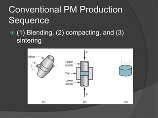
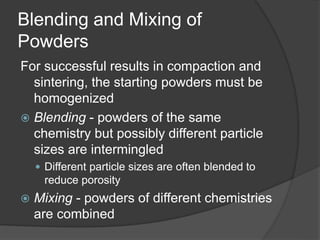
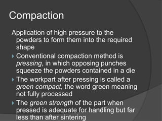
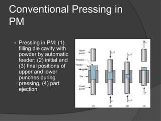
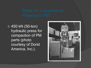
I.Karthikeyan
Assistant Professor,
Mechanical Department .
6/10/2021 1
POWDER METALLURGY
1. The Characterization of Engineering
Powders
2. Production of Metallic Powders
3. Conventional Pressing and Sintering
4. Alternative Pressing and Sintering
Techniques
5. Materials and Products for PM
6. Design Considerations in Powder
Metallurgy
Powder Metallurgy (PM)
Metal processing technology in which parts
are produced from metallic powders
 Usual PM production sequence:
1. Pressing - powders are compressed into
desired shape to produce green compact
○ Accomplished in press using punch-and-die
2. Sintering – green compacts are heated to bond
the particles into a hard, rigid mass
○ Temperatures are below melting point
Why Powder Metallurgy is
Important
 PM parts can be mass produced to net
shape or near net shape, eliminating or
reducing the need for subsequent
machining
 PM process wastes very little material - ~
97% of starting powders are converted to
product
 PM parts can be made with a specified
level of porosity, to produce porous metal
parts
 Filters, oil-impregnated bearings and gears
More Reasons Why PM is
Important
 Certain metals that are difficult to fabricate
by other methods can be shaped by
powder metallurgy
 Tungsten filaments for incandescent lamp bulbs
are made by PM
 Certain alloy combinations and cermets
made by PM cannot be produced in other
ways
 PM compares favorably to most casting
processes in dimensional control
 PM production methods can be automated
for economical production
Limitations and
Disadvantages
 High tooling and equipment costs
 Metallic powders are expensive
 Problems in storing and handling metal powders
◦ Degradation over time, fire hazards with certain metals
 Limitations on part geometry because metal
powders do not readily flow laterally in the die
during pressing
 Variations in density throughout part may be a
problem, especially for complex geometries
PM Work Materials
 Largest tonnage of metals are alloys of
iron, steel, and aluminum
 Other PM metals include copper, nickel,
and refractory metals such as
molybdenum and tungsten
 Metallic carbides such as tungsten
carbide are often included within the
scope of powder metallurgy
Collection of PM Parts (photo
courtesy of Dorst America, Inc.
Engineering Powders
A powder can be defined as a finely
divided particulate solid
 Engineering powders include metals and
ceramics
 Geometric features of engineering
powders:
 Particle size and distribution
 Particle shape and internal structure
 Surface area
Measuring Particle Size
 Most common method uses screens of
different mesh sizes
 Mesh count - refers to the number of
openings per linear inch of screen
 A mesh count of 200 means there are 200
openings per linear inch
 Since the mesh is square, the count is equal
in both directions, and the total number of
openings per square inch is 2002 = 40,000
 Higher mesh count = smaller particle size
Screen Mesh for Sorting Particle
Sizes
Particle Shapes in PM
Interparticle Friction and
Powder Flow
 Friction between particles
affects ability of a powder to
flow readily and pack tightly
 A common test of
interparticle friction is the
angle of repose
◦ Angle formed by a pile of
powders poured from a narrow
funnel
 Larger angles mean greater
interparticle friction
Observations About
Interparticle Friction
 Smaller particle sizes generally show
greater friction and steeper angles
 Spherical shapes have the lowest
interpartical friction
 As shape deviates from spherical, friction
between particles tends to increase
 Easier flow of particles correlates with lower
interparticle friction
 Lubricants are often added to powders to
reduce interparticle friction and facilitate
flow during pressing
Particle Density Measures
 True density - density of the true volume
of the material
 The density of the material if the powders
were melted into a solid mass
 Bulk density - density of the powders in
the loose state after pouring
 Because of pores between particles, bulk
density is less than true density
Packing Factor
Bulk density divided by true density
 Typical values for loose powders are 0.5
to 0.7
 If powders of various sizes are present,
smaller powders fit into spaces between
larger ones, thus higher packing factor
 Packing can be increased by vibrating
the powders, causing them to settle
more tightly
 Pressure applied during compaction
Porosity
Ratio of volume of the pores (empty
spaces) in the powder to the bulk
volume
 In principle, Porosity + Packing factor =
1.0
 The issue is complicated by possible
existence of closed pores in some of the
particles
○ If internal pore volumes are included in above
porosity, then equation is exact
Chemistry and Surface
Films
 Metallic powders are classified as either
 Elemental - consisting of a pure metal
 Pre-alloyed - each particle is an alloy
 Possible surface films include oxides,
silica, adsorbed organic materials, and
moisture
 As a general rule, these films must be
removed prior to shape processing
Production of Metallic
Powders
 In general, producers of metallic
powders are not the same companies
as those that make PM parts
 Any metal can be made into powder
form
 Three principal methods by which
metallic powders are commercially
produced
1. Atomization
2. Chemical
3. Electrolytic
 In addition, mechanical methods are
High velocity gas stream flows through expansion nozzle,
siphoning molten metal and spraying it into container
Gas Atomization Method
Iron Powders for PM
 Produced by decomposition of iron
pentacarbonyl (photo courtesy of GAF
Chemical Corp); particle sizes range
from ~ 0.25 - 3.0 microns (10 to 125 -
in)
Conventional Press and
Sinter
Conventional PM part-making sequence consists
of:
1. Blending and mixing of powders
2. Compaction - pressing into desired shape
3. Sintering - heating to temperature below
melting point to cause solid-state bonding of
particles and strengthening of part
 In addition, secondary operations are
sometimes performed to improve dimensional
accuracy, increase density, and for other
reasons
Conventional PM Production
Sequence
 (1) Blending, (2) compacting, and (3)
sintering
Blending and Mixing of
Powders
For successful results in compaction and
sintering, the starting powders must be
homogenized
 Blending - powders of the same
chemistry but possibly different particle
sizes are intermingled
 Different particle sizes are often blended to
reduce porosity
 Mixing - powders of different chemistries
are combined
Compaction
Application of high pressure to the
powders to form them into the required
shape
 Conventional compaction method is
pressing, in which opposing punches
squeeze the powders contained in a die
 The workpart after pressing is called a
green compact, the word green meaning
not fully processed
 The green strength of the part when
pressed is adequate for handling but far
less than after sintering
Conventional Pressing in
PM
 Pressing in PM: (1)
filling die cavity with
powder by automatic
feeder; (2) initial and
(3) final positions of
upper and lower
punches during
pressing, (4) part
ejection
 450 kN (50-ton)
hydraulic press for
compaction of PM
parts (photo
courtesy of Dorst
America, Inc.).
Press for Conventional
Pressing in PM
Sintering
Heat treatment to bond the metallic
particles, thereby increasing strength
and hardness
 Usually carried out at 70% to 90% of the
metal's melting point (absolute scale)
 Generally agreed among researchers
that the primary driving force for
sintering is reduction of surface energy
 Part shrinkage occurs during sintering
due to pore size reduction
Sintering Sequence on a
Microscopic Scale
 (1) Particle bonding is initiated at contact
points; (2) contact points grow into
"necks"; (3) pores between particles are
reduced in size; (4) grain boundaries
develop between particles in place of
necked regions
 (a) Typical
heat treatment
cycle in
sintering; and
(b) schematic
cross section
of a
continuous
sintering
furnace
Sintering Cycle and Furnace
Densification and Sizing
 Secondary operations are performed on
sintered part to increase density, improve
accuracy, or accomplish additional shaping
 Repressing - pressing in closed die to increase
density and improve properties
 Sizing - pressing to improve dimensional
accuracy
 Coining - pressing details into its surface
 Machining - for geometric features that cannot be
formed by pressing, such as threads and side
Impregnation and Infiltration
 Porosity is a unique and inherent
characteristic of PM technology
 It can be exploited to create special
products by filling the available pore
space with oils, polymers, or metals
 Two categories:
1. Impregnation
2. Infiltration
Impregnation
The term used when oil or other fluid is
permeated into the pores of a sintered
PM part
 Common products are oil-impregnated
bearings, gears, and similar components
 Alternative application is when parts are
impregnated with polymer resins that
seep into the pore spaces in liquid form
and then solidify to create a pressure
tight part
Infiltration
Operation in which the pores of the PM
part are filled with a molten metal
 The melting point of the filler metal must
be below that of the PM part
 Heating the filler metal in contact with
the sintered part so capillary action
draws the filler into the pores
 Resulting structure is nonporous, and the
infiltrated part has a more uniform density, as
well as improved toughness and strength
Alternative Pressing and
Sintering Techniques
 Conventional press and sinter sequence
is the most widely used shaping
technology in powder metallurgy
 Some additional methods for producing
PM parts:
 Isostatic pressing - hydraulic pressure is
applied from all directions to achieve
compaction
 Powder injection molding (PIM) - starting
polymer has 50% to 85% powder content
○ Polymer is removed and PM part is sintered
Materials and Products for
PM
 Raw materials for PM are more
expensive than for other metalworking
because of the additional energy
required to reduce the metal to powder
form
 Accordingly, PM is competitive only in a
certain range of applications
 What are the materials and products
that seem most suited to powder
metallurgy?
PM Materials –
Elemental Powders
A pure metal in particulate form
 Common elemental powders:
◦ Iron
◦ Aluminum
◦ Copper
 Elemental powders can be mixed with other
metal powders to produce alloys that are
difficult to formulate by conventional
methods
◦ Example: tool steels
PM Materials –
Pre-Alloyed Powders
Each particle is an alloy comprised of the
desired chemical composition
 Common pre-alloyed powders:
 Stainless steels
 Certain copper alloys
 High speed steel
PM Products
 Gears, bearings, sprockets, fasteners,
electrical contacts, cutting tools, and various
machinery parts
 Advantage of PM: parts can be made to near
net shape or net shape
 When produced in large quantities, gears and
bearings are ideal for PM because:
◦ Their geometries are defined in two dimensions
◦ There is a need for porosity in the part to serve as a
reservoir for lubricant
PM Parts Classification
System
 The Metal Powder Industries Federation
(MPIF) defines four classes of powder
metallurgy part designs, by level of
difficulty in conventional pressing
 Useful because it indicates some of the
limitations on shape that can be achieved with
conventional PM processing
 (a) Class I Simple thin shapes; (b) Class II
Simple but thicker; (c) Class III Two levels of
thickness; and (d) Class IV Multiple levels of
thickness
Four Classes of PM Parts
Sheet Metal Forming
Techniques
 Blanking
 Stamping
 Pressing
 Drawing
 Deep Drawing
Cost Optimization With
Blanking
 Parts should be nested into patterns to
reduce scrap metal
 Patterns should fit the sheet of metal
they will be punched from to minimize
waste
Producing Better Blanks
• If blanks are not cut properly, the metal
can be stretched be cutting instruments
as it is sheared
• This can lead to microcracks and
distortion in the blank
Microcracks can lead to cracks
and distortion as a blank is shaped
Stamping, Drawing,
Pressing
• Metal clamped
around edges
and forced into
cavity by punch
• Metal can wrinkle,
fracture, buckle,
or not bend
properly
Design to Increase Bend
Precision
 Notching flanges to be bent can prevent
buckling
 Holes placed close to bends can lead to
warping in the bends.
 Flanges should be notched to prevent
tearing of the metal when they are bent
 Reduce localized necks, as these can
lead to tearing.
Examples of Metal Failures in Forming
Equipment for Sheet Metal Forming
 Most machinery used to
press metal use hydraulic
or pneumatic pressing, or
a combination of the two
 Blanks are pressed into a
die specific to the design
Machine for making blank
Factors for Press Selection
 Type of forming
 Size and Shape of Dies
 Size and Shape of Work pieces
 Length of stroke of the slides, operating
speed
 Number of slides: Single, Double, or
Triple action press
More Factors for Press
Selection
 Maximum force required vs. press
capacity
 Type of press
 Press control systems (computer,
mechanical, etc…)
 Features for changing dies
 Safety of machine operators
Example of Blanking
Machine
• State of the art blanking
machine by Minister
Machine Company
• High speed machine for
forming high strength
metals, uses 1,000-ton
press
This is necessary as metals such as steel continue to
be made stronger
Other Examples of Metal forming
machinery
• Steel slitting machine, used
to create strips that can be
quickly stamped into blanks
• Metal bending machine for
tight angles
Economics of Sheet-Forming Operations
• Small, simple parts are very cheap to
make
• This is because large numbers of pieces
can be made quickly, and the cost per
part is minimized
• Large parts, such as aircraft body
paneling, can be very costly to make
• Cost varies substantially based on
thickness of sheet formed
Equipment Costs
• Machines used in manufacture can be
expensive to purchase and maintain
• However, these are largely automated, and
the cost of labor is reduced
Many sheet-formed parts need to
be hand finished to remove things
like burrs on the sheared edges
Burred edge
Conclusion
 Sheet forming is good for applications
where large numbers of parts can be
made from sheet metal.
 Sheet metal pressing becomes cheaper
than other manufacturing processes
~700 units
 Parts and manufacturing processes
must be designed so parts are formed
correctly and quickly

Manufacturing Technology I

  • 1.
  • 2.
    POWDER METALLURGY 1. TheCharacterization of Engineering Powders 2. Production of Metallic Powders 3. Conventional Pressing and Sintering 4. Alternative Pressing and Sintering Techniques 5. Materials and Products for PM 6. Design Considerations in Powder Metallurgy
  • 3.
    Powder Metallurgy (PM) Metalprocessing technology in which parts are produced from metallic powders  Usual PM production sequence: 1. Pressing - powders are compressed into desired shape to produce green compact ○ Accomplished in press using punch-and-die 2. Sintering – green compacts are heated to bond the particles into a hard, rigid mass ○ Temperatures are below melting point
  • 4.
    Why Powder Metallurgyis Important  PM parts can be mass produced to net shape or near net shape, eliminating or reducing the need for subsequent machining  PM process wastes very little material - ~ 97% of starting powders are converted to product  PM parts can be made with a specified level of porosity, to produce porous metal parts  Filters, oil-impregnated bearings and gears
  • 5.
    More Reasons WhyPM is Important  Certain metals that are difficult to fabricate by other methods can be shaped by powder metallurgy  Tungsten filaments for incandescent lamp bulbs are made by PM  Certain alloy combinations and cermets made by PM cannot be produced in other ways  PM compares favorably to most casting processes in dimensional control  PM production methods can be automated for economical production
  • 6.
    Limitations and Disadvantages  Hightooling and equipment costs  Metallic powders are expensive  Problems in storing and handling metal powders ◦ Degradation over time, fire hazards with certain metals  Limitations on part geometry because metal powders do not readily flow laterally in the die during pressing  Variations in density throughout part may be a problem, especially for complex geometries
  • 7.
    PM Work Materials Largest tonnage of metals are alloys of iron, steel, and aluminum  Other PM metals include copper, nickel, and refractory metals such as molybdenum and tungsten  Metallic carbides such as tungsten carbide are often included within the scope of powder metallurgy
  • 8.
    Collection of PMParts (photo courtesy of Dorst America, Inc.
  • 9.
    Engineering Powders A powdercan be defined as a finely divided particulate solid  Engineering powders include metals and ceramics  Geometric features of engineering powders:  Particle size and distribution  Particle shape and internal structure  Surface area
  • 10.
    Measuring Particle Size Most common method uses screens of different mesh sizes  Mesh count - refers to the number of openings per linear inch of screen  A mesh count of 200 means there are 200 openings per linear inch  Since the mesh is square, the count is equal in both directions, and the total number of openings per square inch is 2002 = 40,000  Higher mesh count = smaller particle size
  • 11.
    Screen Mesh forSorting Particle Sizes
  • 12.
  • 13.
    Interparticle Friction and PowderFlow  Friction between particles affects ability of a powder to flow readily and pack tightly  A common test of interparticle friction is the angle of repose ◦ Angle formed by a pile of powders poured from a narrow funnel  Larger angles mean greater interparticle friction
  • 14.
    Observations About Interparticle Friction Smaller particle sizes generally show greater friction and steeper angles  Spherical shapes have the lowest interpartical friction  As shape deviates from spherical, friction between particles tends to increase  Easier flow of particles correlates with lower interparticle friction  Lubricants are often added to powders to reduce interparticle friction and facilitate flow during pressing
  • 15.
    Particle Density Measures True density - density of the true volume of the material  The density of the material if the powders were melted into a solid mass  Bulk density - density of the powders in the loose state after pouring  Because of pores between particles, bulk density is less than true density
  • 16.
    Packing Factor Bulk densitydivided by true density  Typical values for loose powders are 0.5 to 0.7  If powders of various sizes are present, smaller powders fit into spaces between larger ones, thus higher packing factor  Packing can be increased by vibrating the powders, causing them to settle more tightly  Pressure applied during compaction
  • 17.
    Porosity Ratio of volumeof the pores (empty spaces) in the powder to the bulk volume  In principle, Porosity + Packing factor = 1.0  The issue is complicated by possible existence of closed pores in some of the particles ○ If internal pore volumes are included in above porosity, then equation is exact
  • 18.
    Chemistry and Surface Films Metallic powders are classified as either  Elemental - consisting of a pure metal  Pre-alloyed - each particle is an alloy  Possible surface films include oxides, silica, adsorbed organic materials, and moisture  As a general rule, these films must be removed prior to shape processing
  • 19.
    Production of Metallic Powders In general, producers of metallic powders are not the same companies as those that make PM parts  Any metal can be made into powder form  Three principal methods by which metallic powders are commercially produced 1. Atomization 2. Chemical 3. Electrolytic  In addition, mechanical methods are
  • 20.
    High velocity gasstream flows through expansion nozzle, siphoning molten metal and spraying it into container Gas Atomization Method
  • 21.
    Iron Powders forPM  Produced by decomposition of iron pentacarbonyl (photo courtesy of GAF Chemical Corp); particle sizes range from ~ 0.25 - 3.0 microns (10 to 125 - in)
  • 22.
    Conventional Press and Sinter ConventionalPM part-making sequence consists of: 1. Blending and mixing of powders 2. Compaction - pressing into desired shape 3. Sintering - heating to temperature below melting point to cause solid-state bonding of particles and strengthening of part  In addition, secondary operations are sometimes performed to improve dimensional accuracy, increase density, and for other reasons
  • 23.
    Conventional PM Production Sequence (1) Blending, (2) compacting, and (3) sintering
  • 24.
    Blending and Mixingof Powders For successful results in compaction and sintering, the starting powders must be homogenized  Blending - powders of the same chemistry but possibly different particle sizes are intermingled  Different particle sizes are often blended to reduce porosity  Mixing - powders of different chemistries are combined
  • 25.
    Compaction Application of highpressure to the powders to form them into the required shape  Conventional compaction method is pressing, in which opposing punches squeeze the powders contained in a die  The workpart after pressing is called a green compact, the word green meaning not fully processed  The green strength of the part when pressed is adequate for handling but far less than after sintering
  • 26.
    Conventional Pressing in PM Pressing in PM: (1) filling die cavity with powder by automatic feeder; (2) initial and (3) final positions of upper and lower punches during pressing, (4) part ejection
  • 27.
     450 kN(50-ton) hydraulic press for compaction of PM parts (photo courtesy of Dorst America, Inc.). Press for Conventional Pressing in PM
  • 28.
    Sintering Heat treatment tobond the metallic particles, thereby increasing strength and hardness  Usually carried out at 70% to 90% of the metal's melting point (absolute scale)  Generally agreed among researchers that the primary driving force for sintering is reduction of surface energy  Part shrinkage occurs during sintering due to pore size reduction
  • 29.
    Sintering Sequence ona Microscopic Scale  (1) Particle bonding is initiated at contact points; (2) contact points grow into "necks"; (3) pores between particles are reduced in size; (4) grain boundaries develop between particles in place of necked regions
  • 30.
     (a) Typical heattreatment cycle in sintering; and (b) schematic cross section of a continuous sintering furnace Sintering Cycle and Furnace
  • 31.
    Densification and Sizing Secondary operations are performed on sintered part to increase density, improve accuracy, or accomplish additional shaping  Repressing - pressing in closed die to increase density and improve properties  Sizing - pressing to improve dimensional accuracy  Coining - pressing details into its surface  Machining - for geometric features that cannot be formed by pressing, such as threads and side
  • 32.
    Impregnation and Infiltration Porosity is a unique and inherent characteristic of PM technology  It can be exploited to create special products by filling the available pore space with oils, polymers, or metals  Two categories: 1. Impregnation 2. Infiltration
  • 33.
    Impregnation The term usedwhen oil or other fluid is permeated into the pores of a sintered PM part  Common products are oil-impregnated bearings, gears, and similar components  Alternative application is when parts are impregnated with polymer resins that seep into the pore spaces in liquid form and then solidify to create a pressure tight part
  • 34.
    Infiltration Operation in whichthe pores of the PM part are filled with a molten metal  The melting point of the filler metal must be below that of the PM part  Heating the filler metal in contact with the sintered part so capillary action draws the filler into the pores  Resulting structure is nonporous, and the infiltrated part has a more uniform density, as well as improved toughness and strength
  • 35.
    Alternative Pressing and SinteringTechniques  Conventional press and sinter sequence is the most widely used shaping technology in powder metallurgy  Some additional methods for producing PM parts:  Isostatic pressing - hydraulic pressure is applied from all directions to achieve compaction  Powder injection molding (PIM) - starting polymer has 50% to 85% powder content ○ Polymer is removed and PM part is sintered
  • 36.
    Materials and Productsfor PM  Raw materials for PM are more expensive than for other metalworking because of the additional energy required to reduce the metal to powder form  Accordingly, PM is competitive only in a certain range of applications  What are the materials and products that seem most suited to powder metallurgy?
  • 37.
    PM Materials – ElementalPowders A pure metal in particulate form  Common elemental powders: ◦ Iron ◦ Aluminum ◦ Copper  Elemental powders can be mixed with other metal powders to produce alloys that are difficult to formulate by conventional methods ◦ Example: tool steels
  • 38.
    PM Materials – Pre-AlloyedPowders Each particle is an alloy comprised of the desired chemical composition  Common pre-alloyed powders:  Stainless steels  Certain copper alloys  High speed steel
  • 39.
    PM Products  Gears,bearings, sprockets, fasteners, electrical contacts, cutting tools, and various machinery parts  Advantage of PM: parts can be made to near net shape or net shape  When produced in large quantities, gears and bearings are ideal for PM because: ◦ Their geometries are defined in two dimensions ◦ There is a need for porosity in the part to serve as a reservoir for lubricant
  • 40.
    PM Parts Classification System The Metal Powder Industries Federation (MPIF) defines four classes of powder metallurgy part designs, by level of difficulty in conventional pressing  Useful because it indicates some of the limitations on shape that can be achieved with conventional PM processing
  • 41.
     (a) ClassI Simple thin shapes; (b) Class II Simple but thicker; (c) Class III Two levels of thickness; and (d) Class IV Multiple levels of thickness Four Classes of PM Parts
  • 42.
    Sheet Metal Forming Techniques Blanking  Stamping  Pressing  Drawing  Deep Drawing
  • 43.
    Cost Optimization With Blanking Parts should be nested into patterns to reduce scrap metal  Patterns should fit the sheet of metal they will be punched from to minimize waste
  • 44.
    Producing Better Blanks •If blanks are not cut properly, the metal can be stretched be cutting instruments as it is sheared • This can lead to microcracks and distortion in the blank Microcracks can lead to cracks and distortion as a blank is shaped
  • 45.
    Stamping, Drawing, Pressing • Metalclamped around edges and forced into cavity by punch • Metal can wrinkle, fracture, buckle, or not bend properly
  • 46.
    Design to IncreaseBend Precision  Notching flanges to be bent can prevent buckling  Holes placed close to bends can lead to warping in the bends.  Flanges should be notched to prevent tearing of the metal when they are bent  Reduce localized necks, as these can lead to tearing.
  • 47.
    Examples of MetalFailures in Forming
  • 48.
    Equipment for SheetMetal Forming  Most machinery used to press metal use hydraulic or pneumatic pressing, or a combination of the two  Blanks are pressed into a die specific to the design Machine for making blank
  • 49.
    Factors for PressSelection  Type of forming  Size and Shape of Dies  Size and Shape of Work pieces  Length of stroke of the slides, operating speed  Number of slides: Single, Double, or Triple action press
  • 50.
    More Factors forPress Selection  Maximum force required vs. press capacity  Type of press  Press control systems (computer, mechanical, etc…)  Features for changing dies  Safety of machine operators
  • 51.
    Example of Blanking Machine •State of the art blanking machine by Minister Machine Company • High speed machine for forming high strength metals, uses 1,000-ton press This is necessary as metals such as steel continue to be made stronger
  • 52.
    Other Examples ofMetal forming machinery • Steel slitting machine, used to create strips that can be quickly stamped into blanks • Metal bending machine for tight angles
  • 53.
    Economics of Sheet-FormingOperations • Small, simple parts are very cheap to make • This is because large numbers of pieces can be made quickly, and the cost per part is minimized • Large parts, such as aircraft body paneling, can be very costly to make • Cost varies substantially based on thickness of sheet formed
  • 54.
    Equipment Costs • Machinesused in manufacture can be expensive to purchase and maintain • However, these are largely automated, and the cost of labor is reduced Many sheet-formed parts need to be hand finished to remove things like burrs on the sheared edges Burred edge
  • 55.
    Conclusion  Sheet formingis good for applications where large numbers of parts can be made from sheet metal.  Sheet metal pressing becomes cheaper than other manufacturing processes ~700 units  Parts and manufacturing processes must be designed so parts are formed correctly and quickly