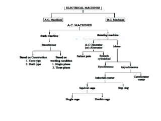
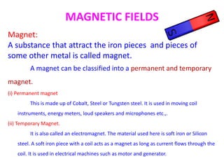
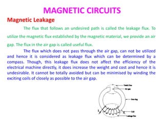
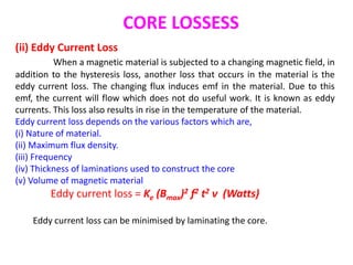
SlideShare a Scribd company logo
1 of 38
Download to read offline
ELECTROMAGNETIC PRINCIPLES
AND MAGNETIC CIRCUITS
Dr. SELVARASU RANGANATHAN
Professor
School of Electrical Engineering and Computing
Adama Science and Technology University
Adma, Ethiopia
MAGNETIC FIELDS
Magnet:
A substance that attract the iron pieces and pieces of
some other metal is called magnet.
A magnet can be classified into a permanent and temporary
magnet.
(i) Permanent magnet
This is made up of Cobalt, Steel or Tungsten steel. It is used in moving coil
instruments, energy meters, loud speakers and microphones etc.,.
(ii) Temporary Magnet.
It is also called an electromagnet. The material used here is soft iron or Silicon
steel. A soft iron piece with a coil acts as a magnet as long as current flows through the
coil. It is used in electrical machines such as motor and generator.
MAGNETIC FIELDS
Magnetic lines of Force:
The imaginary magnetic lines which travel from north pole
to south pole outside the magnet, and south pole to north pole,
inside the magnet are called magnetic lines of force.
Magnetic Field
The region around which the magnetic lines of force acts is called
magnetic field.
MAGNETIC FIELDS
Properties of Magnetic lines of Force:
•Magnetic lines of force are directed from north to south outside a
magnet. The direction is determined by the north pole of a small magnet
held in the field.
•Magnetic lines of force are continuous.
•Magnetic lines of force enter or leave a magnetic surface at right angles.
•Magnetic lines of force cannot cross each other.
•Magnetic lines of force in the same direction tend to repel each other.
•Magnetic lines of force tend to be as short as possible.
•Magnetic lines of force occupy three-dimensional space extending
(theoretically) to infinity.
MAGNETIC FIELDS
Electromagnetism:
A magnetic field is always associated with a current-carrying conductor,
as illustrated in Figure. Exploring the magnetic field by means of a compass, we
observe the following:
The magnetic field is strongest perpendicular to the current direction.
MAGNETIC FIELDS
Ampere's right-hand rule :
If we grasp the conductor with our right hand, the thumb pointing in
the direction of the current, our fingers will point in the same direction as the
north pole of the compass. This method of determining the directions of
current flow in a conductor and the surrounding lines of force is called Am-
pere's right-hand rule as illustrated in Figure.
MAGNETIC FIELDS
We can determine the direction of the magnetic field in a cylindrical
coil of many turns of insulated wire by using our right hand. If we grasp the coil
with our right hand with the fingers pointing in the direction of the current, the
thumb will point in the direction of the north pole. This method of determining
directions of current flow in a coil and magnetic fields of force is another form
of Ampere's right-hand rule.
Magnetic field direction of solenoid by right hand rule
ELECTROMAGNETIC RELATIONSHIPS
Magnetic Flux (Φ)
The total number of lines of force in the magnetic field is called
magnetic flux. It is denoted by ‘Φ’, and its unit is Weber.
Magnetic Flux Density (B)
The magnetic flux passing through unit cross section is called flux
density. It is denoted by ‘B’.
If ‘Φ’ is magnetic flux in Webers
B is flux density in Wb/m2.
then B = Φ/A Wb/m2
Magneto-Motive Force (MMF)
It is the driving force required to drive the magnetic flux through a
magnetic circuit.
The product NI is called magneto-motive force. Its unit is Ampere turns.
MMF = NI (AT)
ELECTROMAGNETIC RELATIONSHIPS
Reluctance (S)
It is the property of magnetic material by which it opposes the
establishment of magnetic flux. It is defined as the ratio of magneto-motive
force to the flux. It is denoted by S and its unit is ampere turns/Wb.
Reluctance, S =mmf/flux=NI/ Φ (AT/Wb)
Permeance
It is the reciprocal of reluctance and is a measure of the case with
which flux can pass through the material. Its unit is Wb/AT.
Permeance = 1/S (Wb/AT)
ELECTROMAGNETIC RELATIONSHIPS
Magnetic Field Strength (H)
It is given by the force experienced by unit north pole
placed at that point. It is denoted by ‘H’.
If ‘Φ’ is the flux in webers
‘F’ is the force in Newton (Nw)
H is the field strength in Nw/Wb.
then H = F/ Φ (Nw/Wb)
H is also given by H =B/µoµr (Nw/Wb)
ELECTROMAGNETIC RELATIONSHIPS
Permeability
The magnetic conductivity of iron as compared to that of air is called
permeability.
The absolute permeability ‘µ’ of a medium is given by, µ=B/H
where B =flux density in Wb/m2
H = magnetic field strength in Nw/Wb
µ is also given by the equation, µ=µoµr
Where µo = 4¶ x 10-7 H/M and µr = Relative permeability
The relative permeability µr of a medium is given by µr = B/B0
where B = flux density in the medium under consideration in Wb/m2
B0 = flux density in vacuum.
The value of µr =1 for air, free space or vacuum.
MAGNETIC CIRCUIT
Analysis of Magnetic Circuit
A magnetic circuit is defined as, the closed path traced by
the magnetic lines of force.
The magnetic circuit can be sub divided into,
(i) Simple magnetic circuit
(ii) Composite magnetic circuit
(iii) Parallel magnetic circuit
MAGNETIC CIRCUITS
(i) Simple Magnetic Circuit
It consists of a closed iron ring wound with a magnetising coil as
shown in fig. The magnetic flux is produced by the coil. Thus the coil acts as a
source of mmf and the reluctance for the establishment of magnetic flux is
offered by the iron ring.
The torroidal ring with a coil of ‘N’ turns.
Let I = current through the coil
Φ = flux in the iron ring (Wb)
A = Area of cross section of the ring (m2).
l = length of the magnetic path in metres
µo = 4¶ x 10-7 H/M and µr = Relative permeability of the ring.
MAGNETIC CIRCUITS
(i) Simple Magnetic Circuit Contd…
MAGNETIC CIRCUITS
(ii) Composite Magnetic Circuit
Practically the magnetic circuits are formed by more than one material,
with different permeability. Such materials can have various length and cross
sectional area. This circuit is called as composite circuit. When those materials
are connected one after the other to form a magnetic circuit is called to be
series magnetic circuit.
MAGNETIC CIRCUITS
(ii) Composite Magnetic Circuit Contd..
MAGNETIC CIRCUITS
(ii) Composite Magnetic Circuit Contd..
MAGNETIC CIRCUITS
(iiI) Parallel Magnetic Circuits
A magnetic circuit is said to be parallel connected if it has more than
one closed path for flux.
At point B, flux have two paths.
(i) flux Φ2 passes through the path BE
(ii) flux Φ3 passes through the path BCFE.
MAGNETIC CIRCUITS
(iiI) Parallel Magnetic Circuits contd…
MAGNETIC CIRCUITS
Magnetic Leakage
The flux that follows an undesired path is called the leakage flux. To
utilize the magnetic flux established by the magnetic material, we provide an air
gap. The flux in the air gap is called useful flux.
The flux which does not pass through the air gap, can not be utilized
and hence it is considered as leakage flux which can be determined by a
compass. Though, this leakage flux does not affect the efficiency of the
electrical machine directly, it does increase the weight and cost and hence it is
undesirable. It cannot be totally avoided but can be minimised by winding the
exciting coils of closely as possible to the air gap.
Comparison of Electric and Magnetic
Circuit
S.No Magnetic Circuit Electric Circuit
1 The path traced by magnetic flux is
defined as magnetic circuit.
Path traced by the current is called as
electric circuit.
2 MMF is the driving force in the
magnetic circuit (Unit is Ampere turns)
Emf is the driving force in an electric
circuit. (Unit is volts)
3 There will be the presence of flux,
(Wb)
There will be the presence of current,
I (A)
4 The magnetic lines will decide the flux The electrons will decide the current.
(i) Similarities
Comparison of Electric and Magnetic
Circuit(ii) Disimilarities
ELECTROMAGNETIC INDUCTION
We have seen the magnetic effects of an electric current. Then it was
Michael Faraday who made attempts, to get emf from magnetic flux. This is
called to be electromagnetic induction.
Law of Electromagnetic Induction
(i) Faraday’s law
Whenever the magnetic flux linking a conductor changes, an emf is
always induced in it. The magnitude of induced emf is proportional to the rate
of change of flux linkages.
e=N dΦ/dt
Where e= induced emf in V
N= Number of turns
dΦ/dt = Rate of change of flux.
ELECTROMAGNETIC INDUCTION
(iI) Lez’s Law
This law states that any induced emf will circulate a current in such a
direction so as to oppose the cause producing it.
e= - N dΦ/dt
Where e= induced emf in V
N= Number of turns
dΦ/dt = Rate of change of flux.
NATURE OF INDUCED EMF
We can get induced emf from a conductor, whenever there is change in
flux, with that conductor.
We can obtain this from two methods. So, the emf is classified as,
(i) Dynamically induced emf and
(ii) Statically induced emf.
(i) Dynamically Induced emf
When the induced emf is from the mechanical movement of coil with
respect to flux, (or) movement of magnet with respect to stationary coil, then it
is called Dynamically induced
emf.
Eg: DC generator, AC generator.
The induced emf will be given by,
e = Blv sin Ɵ (V).
Direction of dynamically induced emf is found by Fleming’s Right Hand Rule.
NATURE OF INDUCED EMF
Fleming’s Right Hand Rule
Stretch the fore finger, middle finger and thumb of right
hand mutually perpendicular to each other. If fore finger
represents the direction of magnetic field, thumb represents the
direction of motion of conductor then the middle finger will
represent the direction of induced emf.
NATURE OF INDUCED EMF
(ii) Statically induced emf.
The induced emf in a coil without any mechanical
movement of coil (or) magnet is called stationary induced emf (or)
statically induced emf.
This is achieved by changing the flux associated with a coil,
by increasing (or) decreasing the current through it rapidly.
Statically induced emf is further classified as,
(a) Self induced emf
(b) Mutually induced emf
NATURE OF INDUCED EMF
(a) Self induced emf
In the set up shown in Fig. the coil is carring a current of I, amps. Due
to this current, flux will be established.
When this current is varied by varying the value of
resistance, the flux linking the coil also changes.
So, an emf will be induced. This is called self-
induced emf.
Simply, the emf induced in a coil due to the
change of its own flux linked with it is called self
induced emf.
The self induced emf will be induced till
the current in the coil is changing and also its
direction can be obtained from Lenz’s law.
NATURE OF INDUCED EMF
(ii) Mutually induced emf
Consider two coils (Say A and B) which are kept near by.
The change in flux in coil A will change the flux linking with coil B. Due
to this an emf will be induced in coil B. This induced emf is called as mutually
induced emf.
Simply, the emf induced in a circuit due to the change in the near by
circuit is called as mutually induced emf.
In Fig. the flux in coil A is linking the coil B.
So, when the current flowing
through coil A (I1) is varied, then Φ1 will be
varied, which inturn changes Φ 12, the flux
linking coil A and coil B. Due to this
variation in the flux linkage, emf will be
induced in coil B and the galvanometer
pointer will deflect in one direction. The
current I1 is varied by varying the resistance
R, in the coil A circuit.
HYSTERESIS LOOP
When we plot the variation in the magnetic parameters with the
change in current, then the result in curve or loop is called as hysteresis curve or
hysteresis loop.
As we know that alternating voltages increases and decreases with respect to
time periodically. In the positive half cycle it magnetises the magnetic circuit
and in the negative half cycle it demagnetises. It is also called as AC operation of
magnetic circuits.
CORE LOSSESS
Core Lossess are classified as
(i) Hysteresis loss
(ii) Eddy Current loss
(i) Hysteresis Loss
When a magnetic material is subjected to a cycle of magnetisation and
demagnetisation, some of the energy loss will occur due to molecular friction.
Energy is thus expanded in the material in over coming this opposition. This loss
is in the form of heat and is called hysteresis loss. It is so called because it
results due to the hysteresis effect in a magnetic material. This effect- results in
the rise of temperature of the machine.
Hysteresis loss = η Bmax1.6 fv (J/S) or Watts.
where,
η = Steinmentz hysteresis co-efficient
f = frequency of reversal of magnetisation
v = volume of magnetic material
CORE LOSSESS
(ii) Eddy Current Loss
When a magnetic material is subjected to a changing magnetic field, in
addition to the hysteresis loss, another loss that occurs in the material is the
eddy current loss. The changing flux induces emf in the material. Due to this
emf, the current will flow which does not do useful work. It is known as eddy
currents. This loss also results in rise in the temperature of the material.
Eddy current loss depends on the various factors which are,
(i) Nature of material.
(ii) Maximum flux density.
(iii) Frequency
(iv) Thickness of laminations used to construct the core
(v) Volume of magnetic material
Eddy current loss = Ke (Bmax)2 f2 t2 v (Watts)
Eddy current loss can be minimised by laminating the core.
ELECTROMAGNETIC PRINCIPLES AND MAGNETIC CIRCUITS

More Related Content

What's hot (20)

Moving iron (MI) instruments
Moving iron (MI) instrumentsMoving iron (MI) instruments
Moving iron (MI) instruments
 
AC & DC
AC & DCAC & DC
AC & DC
 
Electromagnetism..
Electromagnetism..Electromagnetism..
Electromagnetism..
 
Voltage
VoltageVoltage
Voltage
 
Dc circuits
Dc circuitsDc circuits
Dc circuits
 
Magnetic circuit
Magnetic circuitMagnetic circuit
Magnetic circuit
 
Dc motor
Dc motorDc motor
Dc motor
 
Electric field intensity
Electric field intensityElectric field intensity
Electric field intensity
 
Ac fundamentals
Ac fundamentalsAc fundamentals
Ac fundamentals
 
Magnetic field of solenoid
Magnetic field of solenoidMagnetic field of solenoid
Magnetic field of solenoid
 
Chapter 2
Chapter 2Chapter 2
Chapter 2
 
Displacement current
Displacement currentDisplacement current
Displacement current
 
D.C. Circuits
D.C. CircuitsD.C. Circuits
D.C. Circuits
 
Electromagnetic induction
Electromagnetic inductionElectromagnetic induction
Electromagnetic induction
 
CURRENT ELECTRICITY
CURRENT ELECTRICITYCURRENT ELECTRICITY
CURRENT ELECTRICITY
 
Permanent Magnet Moving Coil (PPMC)
Permanent Magnet Moving Coil (PPMC)Permanent Magnet Moving Coil (PPMC)
Permanent Magnet Moving Coil (PPMC)
 
DC MOTORS-UNIT-II.pdf
DC MOTORS-UNIT-II.pdfDC MOTORS-UNIT-II.pdf
DC MOTORS-UNIT-II.pdf
 
Armature Reaction
Armature ReactionArmature Reaction
Armature Reaction
 
Electromagnetism
ElectromagnetismElectromagnetism
Electromagnetism
 
Dc machines
Dc machinesDc machines
Dc machines
 

Similar to ELECTROMAGNETIC PRINCIPLES AND MAGNETIC CIRCUITS

MAGNETIC EFFECTS OF ELECTRIC CURRENT-converted.pptx
MAGNETIC EFFECTS OF ELECTRIC CURRENT-converted.pptxMAGNETIC EFFECTS OF ELECTRIC CURRENT-converted.pptx
MAGNETIC EFFECTS OF ELECTRIC CURRENT-converted.pptxSiddalingeshwarSiddu
 
Electromagnetic induction class 10 ICSE.pptx
Electromagnetic induction class 10 ICSE.pptxElectromagnetic induction class 10 ICSE.pptx
Electromagnetic induction class 10 ICSE.pptxnysa tutorial
 
Art integration project
Art integration projectArt integration project
Art integration projectpiyushyadav168
 
magnetic Circuit.pptx
magnetic Circuit.pptxmagnetic Circuit.pptx
magnetic Circuit.pptxLOCHANBHATT1
 
basic principle of electrical machines
basic principle of electrical machinesbasic principle of electrical machines
basic principle of electrical machinesNebiyu Yissaye
 
Magnetic circuits and magnetic materials
Magnetic circuits and magnetic materialsMagnetic circuits and magnetic materials
Magnetic circuits and magnetic materialskarthik prabhu
 
Eg1108 transformers
Eg1108 transformersEg1108 transformers
Eg1108 transformersVikram Singh
 
Bee(electromagnetism and mmf) lecture 3
Bee(electromagnetism and mmf)  lecture 3Bee(electromagnetism and mmf)  lecture 3
Bee(electromagnetism and mmf) lecture 3ChandrashekharPatil57
 
Chapter 12 physics
Chapter 12 physicsChapter 12 physics
Chapter 12 physicsKrishna Gali
 
Magnetism and AC Fundamentals
Magnetism and AC FundamentalsMagnetism and AC Fundamentals
Magnetism and AC Fundamentalsmaneesh001
 
Magnetic Effects of current
Magnetic Effects of currentMagnetic Effects of current
Magnetic Effects of currentClement Smith
 
Physics_Investigatory_Project_Abhishek_c (1).pdf
Physics_Investigatory_Project_Abhishek_c (1).pdfPhysics_Investigatory_Project_Abhishek_c (1).pdf
Physics_Investigatory_Project_Abhishek_c (1).pdfShankararaman2
 
Cutnell_Ch_21B.ppt used for chutbell I think
Cutnell_Ch_21B.ppt used for chutbell I thinkCutnell_Ch_21B.ppt used for chutbell I think
Cutnell_Ch_21B.ppt used for chutbell I thinkDhanush239214
 

Similar to ELECTROMAGNETIC PRINCIPLES AND MAGNETIC CIRCUITS (20)

Chapter 1
Chapter 1Chapter 1
Chapter 1
 
MAGNETIC EFFECTS OF ELECTRIC CURRENT-converted.pptx
MAGNETIC EFFECTS OF ELECTRIC CURRENT-converted.pptxMAGNETIC EFFECTS OF ELECTRIC CURRENT-converted.pptx
MAGNETIC EFFECTS OF ELECTRIC CURRENT-converted.pptx
 
magnetic circuits
 magnetic circuits magnetic circuits
magnetic circuits
 
Module 1
Module 1Module 1
Module 1
 
Electromagnetic induction class 10 ICSE.pptx
Electromagnetic induction class 10 ICSE.pptxElectromagnetic induction class 10 ICSE.pptx
Electromagnetic induction class 10 ICSE.pptx
 
Art integration project
Art integration projectArt integration project
Art integration project
 
magnetic Circuit.pptx
magnetic Circuit.pptxmagnetic Circuit.pptx
magnetic Circuit.pptx
 
basic principle of electrical machines
basic principle of electrical machinesbasic principle of electrical machines
basic principle of electrical machines
 
Magnetic circuits and magnetic materials
Magnetic circuits and magnetic materialsMagnetic circuits and magnetic materials
Magnetic circuits and magnetic materials
 
Eoc 2
Eoc 2Eoc 2
Eoc 2
 
Eg1108 transformers
Eg1108 transformersEg1108 transformers
Eg1108 transformers
 
Magnets and magnetism
Magnets and magnetismMagnets and magnetism
Magnets and magnetism
 
Chapter1 part1
Chapter1 part1Chapter1 part1
Chapter1 part1
 
Bee(electromagnetism and mmf) lecture 3
Bee(electromagnetism and mmf)  lecture 3Bee(electromagnetism and mmf)  lecture 3
Bee(electromagnetism and mmf) lecture 3
 
Chapter 12 physics
Chapter 12 physicsChapter 12 physics
Chapter 12 physics
 
Magnetism and AC Fundamentals
Magnetism and AC FundamentalsMagnetism and AC Fundamentals
Magnetism and AC Fundamentals
 
Magnetic Effects of current
Magnetic Effects of currentMagnetic Effects of current
Magnetic Effects of current
 
Physics_Investigatory_Project_Abhishek_c (1).pdf
Physics_Investigatory_Project_Abhishek_c (1).pdfPhysics_Investigatory_Project_Abhishek_c (1).pdf
Physics_Investigatory_Project_Abhishek_c (1).pdf
 
Physics project abhishek
Physics project abhishekPhysics project abhishek
Physics project abhishek
 
Cutnell_Ch_21B.ppt used for chutbell I think
Cutnell_Ch_21B.ppt used for chutbell I thinkCutnell_Ch_21B.ppt used for chutbell I think
Cutnell_Ch_21B.ppt used for chutbell I think
 

Recently uploaded

Churning of Butter, Factors affecting .
Churning of Butter, Factors affecting  .Churning of Butter, Factors affecting  .
Churning of Butter, Factors affecting .Satyam Kumar
 
UNIT III ANALOG ELECTRONICS (BASIC ELECTRONICS)
UNIT III ANALOG ELECTRONICS (BASIC ELECTRONICS)UNIT III ANALOG ELECTRONICS (BASIC ELECTRONICS)
UNIT III ANALOG ELECTRONICS (BASIC ELECTRONICS)Dr SOUNDIRARAJ N
 
main PPT.pptx of girls hostel security using rfid
main PPT.pptx of girls hostel security using rfidmain PPT.pptx of girls hostel security using rfid
main PPT.pptx of girls hostel security using rfidNikhilNagaraju
 
Effects of rheological properties on mixing
Effects of rheological properties on mixingEffects of rheological properties on mixing
Effects of rheological properties on mixingviprabot1
 
Introduction-To-Agricultural-Surveillance-Rover.pptx
Introduction-To-Agricultural-Surveillance-Rover.pptxIntroduction-To-Agricultural-Surveillance-Rover.pptx
Introduction-To-Agricultural-Surveillance-Rover.pptxk795866
 
VICTOR MAESTRE RAMIREZ - Planetary Defender on NASA's Double Asteroid Redirec...
VICTOR MAESTRE RAMIREZ - Planetary Defender on NASA's Double Asteroid Redirec...VICTOR MAESTRE RAMIREZ - Planetary Defender on NASA's Double Asteroid Redirec...
VICTOR MAESTRE RAMIREZ - Planetary Defender on NASA's Double Asteroid Redirec...VICTOR MAESTRE RAMIREZ
 
INFLUENCE OF NANOSILICA ON THE PROPERTIES OF CONCRETE
INFLUENCE OF NANOSILICA ON THE PROPERTIES OF CONCRETEINFLUENCE OF NANOSILICA ON THE PROPERTIES OF CONCRETE
INFLUENCE OF NANOSILICA ON THE PROPERTIES OF CONCRETEroselinkalist12
 
Sachpazis Costas: Geotechnical Engineering: A student's Perspective Introduction
Sachpazis Costas: Geotechnical Engineering: A student's Perspective IntroductionSachpazis Costas: Geotechnical Engineering: A student's Perspective Introduction
Sachpazis Costas: Geotechnical Engineering: A student's Perspective IntroductionDr.Costas Sachpazis
 
What are the advantages and disadvantages of membrane structures.pptx
What are the advantages and disadvantages of membrane structures.pptxWhat are the advantages and disadvantages of membrane structures.pptx
What are the advantages and disadvantages of membrane structures.pptxwendy cai
 
Introduction to Machine Learning Unit-3 for II MECH
Introduction to Machine Learning Unit-3 for II MECHIntroduction to Machine Learning Unit-3 for II MECH
Introduction to Machine Learning Unit-3 for II MECHC Sai Kiran
 
Call Us ≽ 8377877756 ≼ Call Girls In Shastri Nagar (Delhi)
Call Us ≽ 8377877756 ≼ Call Girls In Shastri Nagar (Delhi)Call Us ≽ 8377877756 ≼ Call Girls In Shastri Nagar (Delhi)
Call Us ≽ 8377877756 ≼ Call Girls In Shastri Nagar (Delhi)dollysharma2066
 
DATA ANALYTICS PPT definition usage example
DATA ANALYTICS PPT definition usage exampleDATA ANALYTICS PPT definition usage example
DATA ANALYTICS PPT definition usage examplePragyanshuParadkar1
 
EduAI - E learning Platform integrated with AI
EduAI - E learning Platform integrated with AIEduAI - E learning Platform integrated with AI
EduAI - E learning Platform integrated with AIkoyaldeepu123
 
Work Experience-Dalton Park.pptxfvvvvvvv
Work Experience-Dalton Park.pptxfvvvvvvvWork Experience-Dalton Park.pptxfvvvvvvv
Work Experience-Dalton Park.pptxfvvvvvvvLewisJB
 
Concrete Mix Design - IS 10262-2019 - .pptx
Concrete Mix Design - IS 10262-2019 - .pptxConcrete Mix Design - IS 10262-2019 - .pptx
Concrete Mix Design - IS 10262-2019 - .pptxKartikeyaDwivedi3
 

Recently uploaded (20)

Churning of Butter, Factors affecting .
Churning of Butter, Factors affecting  .Churning of Butter, Factors affecting  .
Churning of Butter, Factors affecting .
 
Design and analysis of solar grass cutter.pdf
Design and analysis of solar grass cutter.pdfDesign and analysis of solar grass cutter.pdf
Design and analysis of solar grass cutter.pdf
 
UNIT III ANALOG ELECTRONICS (BASIC ELECTRONICS)
UNIT III ANALOG ELECTRONICS (BASIC ELECTRONICS)UNIT III ANALOG ELECTRONICS (BASIC ELECTRONICS)
UNIT III ANALOG ELECTRONICS (BASIC ELECTRONICS)
 
🔝9953056974🔝!!-YOUNG call girls in Rajendra Nagar Escort rvice Shot 2000 nigh...
🔝9953056974🔝!!-YOUNG call girls in Rajendra Nagar Escort rvice Shot 2000 nigh...🔝9953056974🔝!!-YOUNG call girls in Rajendra Nagar Escort rvice Shot 2000 nigh...
🔝9953056974🔝!!-YOUNG call girls in Rajendra Nagar Escort rvice Shot 2000 nigh...
 
main PPT.pptx of girls hostel security using rfid
main PPT.pptx of girls hostel security using rfidmain PPT.pptx of girls hostel security using rfid
main PPT.pptx of girls hostel security using rfid
 
Effects of rheological properties on mixing
Effects of rheological properties on mixingEffects of rheological properties on mixing
Effects of rheological properties on mixing
 
Introduction-To-Agricultural-Surveillance-Rover.pptx
Introduction-To-Agricultural-Surveillance-Rover.pptxIntroduction-To-Agricultural-Surveillance-Rover.pptx
Introduction-To-Agricultural-Surveillance-Rover.pptx
 
VICTOR MAESTRE RAMIREZ - Planetary Defender on NASA's Double Asteroid Redirec...
VICTOR MAESTRE RAMIREZ - Planetary Defender on NASA's Double Asteroid Redirec...VICTOR MAESTRE RAMIREZ - Planetary Defender on NASA's Double Asteroid Redirec...
VICTOR MAESTRE RAMIREZ - Planetary Defender on NASA's Double Asteroid Redirec...
 
INFLUENCE OF NANOSILICA ON THE PROPERTIES OF CONCRETE
INFLUENCE OF NANOSILICA ON THE PROPERTIES OF CONCRETEINFLUENCE OF NANOSILICA ON THE PROPERTIES OF CONCRETE
INFLUENCE OF NANOSILICA ON THE PROPERTIES OF CONCRETE
 
9953056974 Call Girls In South Ex, Escorts (Delhi) NCR.pdf
9953056974 Call Girls In South Ex, Escorts (Delhi) NCR.pdf9953056974 Call Girls In South Ex, Escorts (Delhi) NCR.pdf
9953056974 Call Girls In South Ex, Escorts (Delhi) NCR.pdf
 
Sachpazis Costas: Geotechnical Engineering: A student's Perspective Introduction
Sachpazis Costas: Geotechnical Engineering: A student's Perspective IntroductionSachpazis Costas: Geotechnical Engineering: A student's Perspective Introduction
Sachpazis Costas: Geotechnical Engineering: A student's Perspective Introduction
 
What are the advantages and disadvantages of membrane structures.pptx
What are the advantages and disadvantages of membrane structures.pptxWhat are the advantages and disadvantages of membrane structures.pptx
What are the advantages and disadvantages of membrane structures.pptx
 
Introduction to Machine Learning Unit-3 for II MECH
Introduction to Machine Learning Unit-3 for II MECHIntroduction to Machine Learning Unit-3 for II MECH
Introduction to Machine Learning Unit-3 for II MECH
 
Exploring_Network_Security_with_JA3_by_Rakesh Seal.pptx
Exploring_Network_Security_with_JA3_by_Rakesh Seal.pptxExploring_Network_Security_with_JA3_by_Rakesh Seal.pptx
Exploring_Network_Security_with_JA3_by_Rakesh Seal.pptx
 
Call Us ≽ 8377877756 ≼ Call Girls In Shastri Nagar (Delhi)
Call Us ≽ 8377877756 ≼ Call Girls In Shastri Nagar (Delhi)Call Us ≽ 8377877756 ≼ Call Girls In Shastri Nagar (Delhi)
Call Us ≽ 8377877756 ≼ Call Girls In Shastri Nagar (Delhi)
 
DATA ANALYTICS PPT definition usage example
DATA ANALYTICS PPT definition usage exampleDATA ANALYTICS PPT definition usage example
DATA ANALYTICS PPT definition usage example
 
POWER SYSTEMS-1 Complete notes examples
POWER SYSTEMS-1 Complete notes  examplesPOWER SYSTEMS-1 Complete notes  examples
POWER SYSTEMS-1 Complete notes examples
 
EduAI - E learning Platform integrated with AI
EduAI - E learning Platform integrated with AIEduAI - E learning Platform integrated with AI
EduAI - E learning Platform integrated with AI
 
Work Experience-Dalton Park.pptxfvvvvvvv
Work Experience-Dalton Park.pptxfvvvvvvvWork Experience-Dalton Park.pptxfvvvvvvv
Work Experience-Dalton Park.pptxfvvvvvvv
 
Concrete Mix Design - IS 10262-2019 - .pptx
Concrete Mix Design - IS 10262-2019 - .pptxConcrete Mix Design - IS 10262-2019 - .pptx
Concrete Mix Design - IS 10262-2019 - .pptx
 

ELECTROMAGNETIC PRINCIPLES AND MAGNETIC CIRCUITS

  • 1. ELECTROMAGNETIC PRINCIPLES AND MAGNETIC CIRCUITS Dr. SELVARASU RANGANATHAN Professor School of Electrical Engineering and Computing Adama Science and Technology University Adma, Ethiopia
  • 2.
  • 3.
  • 4. MAGNETIC FIELDS Magnet: A substance that attract the iron pieces and pieces of some other metal is called magnet. A magnet can be classified into a permanent and temporary magnet. (i) Permanent magnet This is made up of Cobalt, Steel or Tungsten steel. It is used in moving coil instruments, energy meters, loud speakers and microphones etc.,. (ii) Temporary Magnet. It is also called an electromagnet. The material used here is soft iron or Silicon steel. A soft iron piece with a coil acts as a magnet as long as current flows through the coil. It is used in electrical machines such as motor and generator.
  • 5. MAGNETIC FIELDS Magnetic lines of Force: The imaginary magnetic lines which travel from north pole to south pole outside the magnet, and south pole to north pole, inside the magnet are called magnetic lines of force. Magnetic Field The region around which the magnetic lines of force acts is called magnetic field.
  • 6. MAGNETIC FIELDS Properties of Magnetic lines of Force: •Magnetic lines of force are directed from north to south outside a magnet. The direction is determined by the north pole of a small magnet held in the field. •Magnetic lines of force are continuous. •Magnetic lines of force enter or leave a magnetic surface at right angles. •Magnetic lines of force cannot cross each other. •Magnetic lines of force in the same direction tend to repel each other. •Magnetic lines of force tend to be as short as possible. •Magnetic lines of force occupy three-dimensional space extending (theoretically) to infinity.
  • 7. MAGNETIC FIELDS Electromagnetism: A magnetic field is always associated with a current-carrying conductor, as illustrated in Figure. Exploring the magnetic field by means of a compass, we observe the following: The magnetic field is strongest perpendicular to the current direction.
  • 8. MAGNETIC FIELDS Ampere's right-hand rule : If we grasp the conductor with our right hand, the thumb pointing in the direction of the current, our fingers will point in the same direction as the north pole of the compass. This method of determining the directions of current flow in a conductor and the surrounding lines of force is called Am- pere's right-hand rule as illustrated in Figure.
  • 9. MAGNETIC FIELDS We can determine the direction of the magnetic field in a cylindrical coil of many turns of insulated wire by using our right hand. If we grasp the coil with our right hand with the fingers pointing in the direction of the current, the thumb will point in the direction of the north pole. This method of determining directions of current flow in a coil and magnetic fields of force is another form of Ampere's right-hand rule. Magnetic field direction of solenoid by right hand rule
  • 10. ELECTROMAGNETIC RELATIONSHIPS Magnetic Flux (Φ) The total number of lines of force in the magnetic field is called magnetic flux. It is denoted by ‘Φ’, and its unit is Weber. Magnetic Flux Density (B) The magnetic flux passing through unit cross section is called flux density. It is denoted by ‘B’. If ‘Φ’ is magnetic flux in Webers B is flux density in Wb/m2. then B = Φ/A Wb/m2 Magneto-Motive Force (MMF) It is the driving force required to drive the magnetic flux through a magnetic circuit. The product NI is called magneto-motive force. Its unit is Ampere turns. MMF = NI (AT)
  • 11. ELECTROMAGNETIC RELATIONSHIPS Reluctance (S) It is the property of magnetic material by which it opposes the establishment of magnetic flux. It is defined as the ratio of magneto-motive force to the flux. It is denoted by S and its unit is ampere turns/Wb. Reluctance, S =mmf/flux=NI/ Φ (AT/Wb) Permeance It is the reciprocal of reluctance and is a measure of the case with which flux can pass through the material. Its unit is Wb/AT. Permeance = 1/S (Wb/AT)
  • 12. ELECTROMAGNETIC RELATIONSHIPS Magnetic Field Strength (H) It is given by the force experienced by unit north pole placed at that point. It is denoted by ‘H’. If ‘Φ’ is the flux in webers ‘F’ is the force in Newton (Nw) H is the field strength in Nw/Wb. then H = F/ Φ (Nw/Wb) H is also given by H =B/µoµr (Nw/Wb)
  • 13. ELECTROMAGNETIC RELATIONSHIPS Permeability The magnetic conductivity of iron as compared to that of air is called permeability. The absolute permeability ‘µ’ of a medium is given by, µ=B/H where B =flux density in Wb/m2 H = magnetic field strength in Nw/Wb µ is also given by the equation, µ=µoµr Where µo = 4¶ x 10-7 H/M and µr = Relative permeability The relative permeability µr of a medium is given by µr = B/B0 where B = flux density in the medium under consideration in Wb/m2 B0 = flux density in vacuum. The value of µr =1 for air, free space or vacuum.
  • 14. MAGNETIC CIRCUIT Analysis of Magnetic Circuit A magnetic circuit is defined as, the closed path traced by the magnetic lines of force. The magnetic circuit can be sub divided into, (i) Simple magnetic circuit (ii) Composite magnetic circuit (iii) Parallel magnetic circuit
  • 15. MAGNETIC CIRCUITS (i) Simple Magnetic Circuit It consists of a closed iron ring wound with a magnetising coil as shown in fig. The magnetic flux is produced by the coil. Thus the coil acts as a source of mmf and the reluctance for the establishment of magnetic flux is offered by the iron ring. The torroidal ring with a coil of ‘N’ turns. Let I = current through the coil Φ = flux in the iron ring (Wb) A = Area of cross section of the ring (m2). l = length of the magnetic path in metres µo = 4¶ x 10-7 H/M and µr = Relative permeability of the ring.
  • 16. MAGNETIC CIRCUITS (i) Simple Magnetic Circuit Contd…
  • 17. MAGNETIC CIRCUITS (ii) Composite Magnetic Circuit Practically the magnetic circuits are formed by more than one material, with different permeability. Such materials can have various length and cross sectional area. This circuit is called as composite circuit. When those materials are connected one after the other to form a magnetic circuit is called to be series magnetic circuit.
  • 18. MAGNETIC CIRCUITS (ii) Composite Magnetic Circuit Contd..
  • 19. MAGNETIC CIRCUITS (ii) Composite Magnetic Circuit Contd..
  • 20. MAGNETIC CIRCUITS (iiI) Parallel Magnetic Circuits A magnetic circuit is said to be parallel connected if it has more than one closed path for flux. At point B, flux have two paths. (i) flux Φ2 passes through the path BE (ii) flux Φ3 passes through the path BCFE.
  • 21. MAGNETIC CIRCUITS (iiI) Parallel Magnetic Circuits contd…
  • 22. MAGNETIC CIRCUITS Magnetic Leakage The flux that follows an undesired path is called the leakage flux. To utilize the magnetic flux established by the magnetic material, we provide an air gap. The flux in the air gap is called useful flux. The flux which does not pass through the air gap, can not be utilized and hence it is considered as leakage flux which can be determined by a compass. Though, this leakage flux does not affect the efficiency of the electrical machine directly, it does increase the weight and cost and hence it is undesirable. It cannot be totally avoided but can be minimised by winding the exciting coils of closely as possible to the air gap.
  • 23. Comparison of Electric and Magnetic Circuit S.No Magnetic Circuit Electric Circuit 1 The path traced by magnetic flux is defined as magnetic circuit. Path traced by the current is called as electric circuit. 2 MMF is the driving force in the magnetic circuit (Unit is Ampere turns) Emf is the driving force in an electric circuit. (Unit is volts) 3 There will be the presence of flux, (Wb) There will be the presence of current, I (A) 4 The magnetic lines will decide the flux The electrons will decide the current. (i) Similarities
  • 24. Comparison of Electric and Magnetic Circuit(ii) Disimilarities
  • 25. ELECTROMAGNETIC INDUCTION We have seen the magnetic effects of an electric current. Then it was Michael Faraday who made attempts, to get emf from magnetic flux. This is called to be electromagnetic induction. Law of Electromagnetic Induction (i) Faraday’s law Whenever the magnetic flux linking a conductor changes, an emf is always induced in it. The magnitude of induced emf is proportional to the rate of change of flux linkages. e=N dΦ/dt Where e= induced emf in V N= Number of turns dΦ/dt = Rate of change of flux.
  • 26. ELECTROMAGNETIC INDUCTION (iI) Lez’s Law This law states that any induced emf will circulate a current in such a direction so as to oppose the cause producing it. e= - N dΦ/dt Where e= induced emf in V N= Number of turns dΦ/dt = Rate of change of flux.
  • 27. NATURE OF INDUCED EMF We can get induced emf from a conductor, whenever there is change in flux, with that conductor. We can obtain this from two methods. So, the emf is classified as, (i) Dynamically induced emf and (ii) Statically induced emf. (i) Dynamically Induced emf When the induced emf is from the mechanical movement of coil with respect to flux, (or) movement of magnet with respect to stationary coil, then it is called Dynamically induced emf. Eg: DC generator, AC generator. The induced emf will be given by, e = Blv sin Ɵ (V). Direction of dynamically induced emf is found by Fleming’s Right Hand Rule.
  • 28. NATURE OF INDUCED EMF Fleming’s Right Hand Rule Stretch the fore finger, middle finger and thumb of right hand mutually perpendicular to each other. If fore finger represents the direction of magnetic field, thumb represents the direction of motion of conductor then the middle finger will represent the direction of induced emf.
  • 29. NATURE OF INDUCED EMF (ii) Statically induced emf. The induced emf in a coil without any mechanical movement of coil (or) magnet is called stationary induced emf (or) statically induced emf. This is achieved by changing the flux associated with a coil, by increasing (or) decreasing the current through it rapidly. Statically induced emf is further classified as, (a) Self induced emf (b) Mutually induced emf
  • 30. NATURE OF INDUCED EMF (a) Self induced emf In the set up shown in Fig. the coil is carring a current of I, amps. Due to this current, flux will be established. When this current is varied by varying the value of resistance, the flux linking the coil also changes. So, an emf will be induced. This is called self- induced emf. Simply, the emf induced in a coil due to the change of its own flux linked with it is called self induced emf. The self induced emf will be induced till the current in the coil is changing and also its direction can be obtained from Lenz’s law.
  • 31. NATURE OF INDUCED EMF (ii) Mutually induced emf Consider two coils (Say A and B) which are kept near by. The change in flux in coil A will change the flux linking with coil B. Due to this an emf will be induced in coil B. This induced emf is called as mutually induced emf. Simply, the emf induced in a circuit due to the change in the near by circuit is called as mutually induced emf. In Fig. the flux in coil A is linking the coil B. So, when the current flowing through coil A (I1) is varied, then Φ1 will be varied, which inturn changes Φ 12, the flux linking coil A and coil B. Due to this variation in the flux linkage, emf will be induced in coil B and the galvanometer pointer will deflect in one direction. The current I1 is varied by varying the resistance R, in the coil A circuit.
  • 32. HYSTERESIS LOOP When we plot the variation in the magnetic parameters with the change in current, then the result in curve or loop is called as hysteresis curve or hysteresis loop. As we know that alternating voltages increases and decreases with respect to time periodically. In the positive half cycle it magnetises the magnetic circuit and in the negative half cycle it demagnetises. It is also called as AC operation of magnetic circuits.
  • 33. CORE LOSSESS Core Lossess are classified as (i) Hysteresis loss (ii) Eddy Current loss (i) Hysteresis Loss When a magnetic material is subjected to a cycle of magnetisation and demagnetisation, some of the energy loss will occur due to molecular friction. Energy is thus expanded in the material in over coming this opposition. This loss is in the form of heat and is called hysteresis loss. It is so called because it results due to the hysteresis effect in a magnetic material. This effect- results in the rise of temperature of the machine. Hysteresis loss = η Bmax1.6 fv (J/S) or Watts. where, η = Steinmentz hysteresis co-efficient f = frequency of reversal of magnetisation v = volume of magnetic material
  • 34. CORE LOSSESS (ii) Eddy Current Loss When a magnetic material is subjected to a changing magnetic field, in addition to the hysteresis loss, another loss that occurs in the material is the eddy current loss. The changing flux induces emf in the material. Due to this emf, the current will flow which does not do useful work. It is known as eddy currents. This loss also results in rise in the temperature of the material. Eddy current loss depends on the various factors which are, (i) Nature of material. (ii) Maximum flux density. (iii) Frequency (iv) Thickness of laminations used to construct the core (v) Volume of magnetic material Eddy current loss = Ke (Bmax)2 f2 t2 v (Watts) Eddy current loss can be minimised by laminating the core.