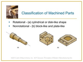
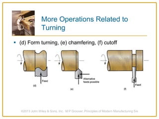
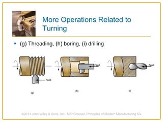
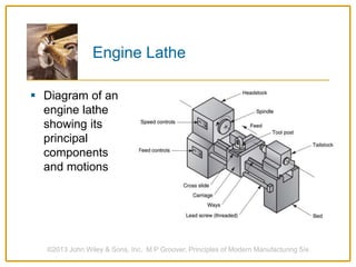
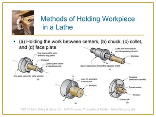
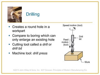
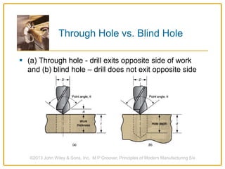
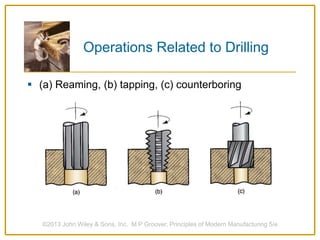
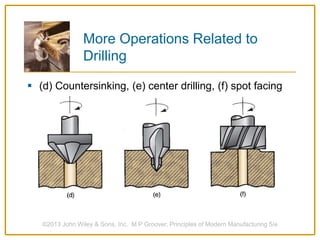
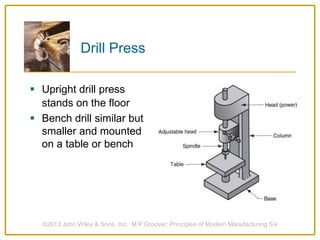
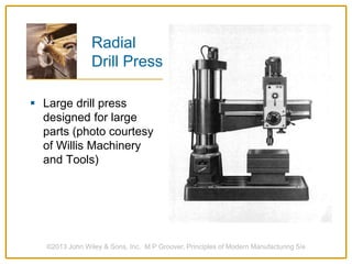
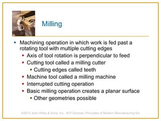
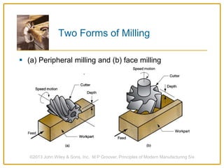
MACHINING OPERATIONS
AND MACHINE TOOLS
1. Turning and Related Operations
2. Drilling and Related Operations
3. Milling
4. Machining Centers and Turning Centers
5. Other Machining Operations
6. Machining Operations for Special Geometries
7. High Speed Machining
©2013 John Wiley & Sons, Inc. M P Groover, Principles of Modern Manufacturing 5/e
Machining
 Material removal process in which a sharp cutting
tool is used to mechanically cut away material so that
the desired part geometry remains
 Most common application: metal parts
 Most versatile of all manufacturing processes for
producing a variety of part shapes and geometric
features with high precision and accuracy
 Casting can also produce a variety of shapes,
but in general is not as accurate as machining
©2013 John Wiley & Sons, Inc. M P Groover, Principles of Modern Manufacturing 5/e
 Rotational - (a) cylindrical or disk-like shape
 Nonrotational - (b) block-like and plate-like
©2013 John Wiley & Sons, Inc. M P Groover, Principles of Modern Manufacturing 5/e
Classification of Machined Parts
Machining Operations and Part
Geometry
 Each machining operation produces a characteristic
part geometry due to two factors:
1. Relative motions between tool and workpart
• Generating – part geometry determined by feed
trajectory of cutting tool
2. Shape of the cutting tool
• Forming – part geometry is created by the
shape of the cutting tool
©2013 John Wiley & Sons, Inc. M P Groover, Principles of Modern Manufacturing 5/e
 Generating shape: (a) straight turning, (b) taper turning, (c)
contour turning, (d) plain milling, (e) profile milling
©2013 John Wiley & Sons, Inc. M P Groover, Principles of Modern Manufacturing 5/e
Generating Shape
 Forming to create shape: (a) form turning, (b) drilling, and (c)
broaching
©2013 John Wiley & Sons, Inc. M P Groover, Principles of Modern Manufacturing 5/e
Forming to Create Shape
 Combination of forming and generating to create shape: (a)
thread cutting on a lathe, and (b) slot milling
©2013 John Wiley & Sons, Inc. M P Groover, Principles of Modern Manufacturing 5/e
Forming and Generating
Turning
 Single point cutting tool removes material from a
rotating workpiece to generate a cylindrical shape
 Performed on a machine tool called a lathe
 Variations of turning performed on a lathe
 Facing
 Contour turning
 Chamfering
 Cutoff
 Threading
©2013 John Wiley & Sons, Inc. M P Groover, Principles of Modern Manufacturing 5/e
Turning Operation
Turning Operation
 Close-up view of a
turning operation on
steel using a titanium
nitride coated carbide
cutting insert (photo
courtesy of Kennametal
Inc.)
©2013 John Wiley & Sons, Inc. M P Groover, Principles of Modern Manufacturing 5/e
Operations Related to Turning
 (a) Facing, (b) taper turning, (c) contour turning
©2013 John Wiley & Sons, Inc. M P Groover, Principles of Modern Manufacturing 5/e
More Operations Related to
Turning
 (d) Form turning, (e) chamfering, (f) cutoff
©2013 John Wiley & Sons, Inc. M P Groover, Principles of Modern Manufacturing 5/e
More Operations Related to
Turning
 (g) Threading, (h) boring, (i) drilling
©2013 John Wiley & Sons, Inc. M P Groover, Principles of Modern Manufacturing 5/e
Engine Lathe
 Diagram of an
engine lathe
showing its
principal
components
and motions
©2013 John Wiley & Sons, Inc. M P Groover, Principles of Modern Manufacturing 5/e
Methods of Holding Workpiece
in a Lathe
 (a) Holding the work between centers, (b) chuck, (c) collet,
and (d) face plate
©2013 John Wiley & Sons, Inc. M P Groover, Principles of Modern Manufacturing 5/e
Other Production Turning
Machines
 Turret lathe
 Chucking machine
 Bar machine
 Automatic screw machine
 Multiple spindle bar machine
©2013 John Wiley & Sons, Inc. M P Groover, Principles of Modern Manufacturing 5/e
Turret Lathe
 Tailstock replaced by “turret” that holds up to six tools
 Tools rapidly brought into action by indexing the
turret
 Tool post replaced by four-sided turret to index
four tools
 Applications: high production work that requires a
sequence of cuts on the part
©2013 John Wiley & Sons, Inc. M P Groover, Principles of Modern Manufacturing 5/e
 https://youtu.be/OehmgbZBVmc
©2013 John Wiley & Sons, Inc. M P Groover, Principles of Modern Manufacturing 5/e
Chucking Machine
 Uses chuck in its spindle to hold workpart
 No tailstock, so parts cannot be mounted between
centers
 Cutting tool actions controlled automatically
 Operator’s job: to load and unload parts
 Applications: short, light-weight parts
©2013 John Wiley & Sons, Inc. M P Groover, Principles of Modern Manufacturing 5/e
Bar Machine
 Similar to chucking machine except collet replaces
chuck, permitting long bar stock to be fed through
headstock
 At the end of the machining cycle, a cutoff
operation separates the new part
 Highly automated
 Computer numerical control
 Applications: high production of rotational parts
©2013 John Wiley & Sons, Inc. M P Groover, Principles of Modern Manufacturing 5/e
Automatic Screw Machine
 Same as automatic bar machine but smaller
 Applications: high production of screws and similar
small hardware items
©2013 John Wiley & Sons, Inc. M P Groover, Principles of Modern Manufacturing 5/e
Multiple Spindle Bar Machines
 More than one spindle, so multiple parts machined
simultaneously by multiple tools
 Example: six spindle automatic bar machine works
on six parts at a time
 After each machining cycle, spindles (including
collets and workbars) are indexed (rotated) to next
position
©2013 John Wiley & Sons, Inc. M P Groover, Principles of Modern Manufacturing 5/e
 (a) Part; (b) sequence of operations: (1) feed stock to stop,
(2) turn main diameter, (3) form second diameter and
spotface, (4) drill, (5) chamfer, and (6) cutoff
©2013 John Wiley & Sons, Inc. M P Groover, Principles of Modern Manufacturing 5/e
Six Spindle Bar Machine
Boring
 Difference between boring and turning:
 Boring is performed on the inside diameter of an
existing hole
 Turning is performed on the outside diameter of
an existing cylinder
 In effect, boring is internal turning operation
 Boring machines
 Horizontal or vertical - refers to the orientation of
the axis of rotation of machine spindle
©2013 John Wiley & Sons, Inc. M P Groover, Principles of Modern Manufacturing 5/e
Vertical Boring Mill
 Applications:
Large, heavy
workparts that
have low L/D ratio
©2013 John Wiley & Sons, Inc. M P Groover, Principles of Modern Manufacturing 5/e
 Creates a round hole in a
workpart
 Compare to boring which can
only enlarge an existing hole
 Cutting tool called a drill or
drill bit
 Machine tool: drill press
©2013 John Wiley & Sons, Inc. M P Groover, Principles of Modern Manufacturing 5/e
Drilling
Through Hole vs. Blind Hole
 (a) Through hole - drill exits opposite side of work
and (b) blind hole – drill does not exit opposite side
©2013 John Wiley & Sons, Inc. M P Groover, Principles of Modern Manufacturing 5/e
Operations Related to Drilling
©2013 John Wiley & Sons, Inc. M P Groover, Principles of Modern Manufacturing 5/e
 (a) Reaming, (b) tapping, (c) counterboring
More Operations Related to
Drilling
 (d) Countersinking, (e) center drilling, (f) spot facing
©2013 John Wiley & Sons, Inc. M P Groover, Principles of Modern Manufacturing 5/e
 Upright drill press
stands on the floor
 Bench drill similar but
smaller and mounted
on a table or bench
©2013 John Wiley & Sons, Inc. M P Groover, Principles of Modern Manufacturing 5/e
Drill Press
Radial
Drill Press
 Large drill press
designed for large
parts (photo courtesy
of Willis Machinery
and Tools)
©2013 John Wiley & Sons, Inc. M P Groover, Principles of Modern Manufacturing 5/e
Milling
 Machining operation in which work is fed past a
rotating tool with multiple cutting edges
 Axis of tool rotation is perpendicular to feed
 Cutting tool called a milling cutter
 Cutting edges called teeth
 Machine tool called a milling machine
 Interrupted cutting operation
 Basic milling operation creates a planar surface
 Other geometries possible
©2013 John Wiley & Sons, Inc. M P Groover, Principles of Modern Manufacturing 5/e
Two Forms of Milling
 (a) Peripheral milling and (b) face milling
©2013 John Wiley & Sons, Inc. M P Groover, Principles of Modern Manufacturing 5/e
Peripheral Milling vs.
Face Milling
 Peripheral milling
 Cutter axis parallel to surface being machined
 Cutting edges on outside periphery of cutter
 Face milling
 Cutter axis perpendicular to surface being milled
 Cutting edges on both the end and outside
periphery of the cutter
©2013 John Wiley & Sons, Inc. M P Groover, Principles of Modern Manufacturing 5/e
Types of Peripheral Milling
 (a) Slab milling, (b) slotting, (c) side milling, (e) straddle
milling, and (e) form milling
©2013 John Wiley & Sons, Inc. M P Groover, Principles of Modern Manufacturing 5/e
Types of Face Milling
 (a) Conventional face milling, (b) partial face milling, and
(c) end milling
©2013 John Wiley & Sons, Inc. M P Groover, Principles of Modern Manufacturing 5/e
Types of Face Milling
 (d) Profile milling, (e) pocket milling, and (f) surface
contouring
©2013 John Wiley & Sons, Inc. M P Groover, Principles of Modern Manufacturing 5/e
Face Milling
 High speed face
milling operation
using indexable
inserts (photo
courtesy of
Kennametal Inc.)
©2013 John Wiley & Sons, Inc. M P Groover, Principles of Modern Manufacturing 5/e
Knee-And-Column Milling
Machines
 (a) Horizontal and (b) vertical knee-and-column
milling machines
©2013 John Wiley & Sons, Inc. M P Groover, Principles of Modern Manufacturing 5/e
Machining Center
 Highly automated machine tool that can perform
multiple machining operations under CNC control in
one setup with minimal human attention
 Typical operations are milling and drilling
 Three, four, or five axes
 Other features:
 Automatic tool-changing
 Pallet shuttles
 Automatic workpart positioning
©2013 John Wiley & Sons, Inc. M P Groover, Principles of Modern Manufacturing 5/e
CNC Machining Center
©2013 John Wiley & Sons, Inc. M P Groover, Principles of Modern Manufacturing 5/e
(Photo
courtesy of
Cincinnati
Milacron)
CNC Turning Center - Industrial
Robot to Load and Unload Parts
©2013 John Wiley & Sons, Inc. M P Groover, Principles of Modern Manufacturing 5/e
(Photo
courtesy
of
Cincinnati
Milacron)
Mill-Turn Centers
 Highly automated machine tool that can perform
turning, milling, and drilling operations in one setup
 General configuration of a turning center
 Can position a cylindrical workpart at a specified
angle so a rotating cutting tool (e.g., milling cutter)
can machine features into outside surface of part
 Conventional turning center cannot stop
workpart at a defined angular position and does
not include rotating tool spindles
©2013 John Wiley & Sons, Inc. M P Groover, Principles of Modern Manufacturing 5/e
 (a) Part and (b) sequence of operations : (1) turn second
diameter, (2) mill flat, (3) drill hole, and (4) cutoff
©2013 John Wiley & Sons, Inc. M P Groover, Principles of Modern Manufacturing 5/e
Operation of Mill-Turn Center
 Similar operations, both use a single point cutting
tool moved linearly relative to the workpart
©2013 John Wiley & Sons, Inc. M P Groover, Principles of Modern Manufacturing 5/e
Shaping and Planing
Shaping and Planing
 A straight, flat surface is created in both operations
 Interrupted cutting operation
 Subjects tool to impact loading when entering
work
 Typical tooling: single point high speed steel
tools
 Low cutting speeds due to start-and-stop motion
©2013 John Wiley & Sons, Inc. M P Groover, Principles of Modern Manufacturing 5/e
Shaper
©2013 John Wiley & Sons, Inc. M P Groover, Principles of Modern Manufacturing 5/e
Planer
 A multiple tooth cutting tool is moved linearly
relative to work in direction of tool axis
©2013 John Wiley & Sons, Inc. M P Groover, Principles of Modern Manufacturing 5/e
Broaching
Broaching
 Advantages:
 Good surface finish
 Close tolerances
 Variety of work shapes possible
 Cutting tool called a broach
 Owing to complicated and often custom-shaped
geometry, tooling is expensive
©2013 John Wiley & Sons, Inc. M P Groover, Principles of Modern Manufacturing 5/e
 (a) External and (b) internal broaching (cross-
hatching indicates surface broached)
©2013 John Wiley & Sons, Inc. M P Groover, Principles of Modern Manufacturing 5/e
Broaching
Sawing
 Cuts narrow slit in work by a tool consisting of a
series of narrowly spaced teeth
 Tool called a saw blade
 Typical functions:
 Separate a workpart into two pieces
 Cut off unwanted portions of part
 Cut outline of flat part
©2013 John Wiley & Sons, Inc. M P Groover, Principles of Modern Manufacturing 5/e
Sawing
 (a) Power hacksaw, (b) bandsaw (vertical), and (c) circular
saw
©2013 John Wiley & Sons, Inc. M P Groover, Principles of Modern Manufacturing 5/e
Machining Operations for
Special Geometries
 Screw threads
 Gear teeth
©2013 John Wiley & Sons, Inc. M P Groover, Principles of Modern Manufacturing 5/e
Cutting Screw Threads
 Methods for producing external threads
 Single-point threading
 Threading die
 Thread chasing using self-opening threading dies
 Thread milling
 Methods for producing internal threads
 Tapping - using a solid tap
 Collapsible taps - cutting teeth retract for quick
removal from hole
©2013 John Wiley & Sons, Inc. M P Groover, Principles of Modern Manufacturing 5/e
Cutting External Screw Threads
 (left) Single-point thread cutting and (right) threading die
©2013 John Wiley & Sons, Inc. M P Groover, Principles of Modern Manufacturing 5/e
Thread Milling Using a
Form-Milling Cutter
©2013 John Wiley & Sons, Inc. M P Groover, Principles of Modern Manufacturing 5/e
Principal Operations for
Machining Gear Teeth
 Form milling - use of a form milling cutter
 Gear hobbing - also milling but using a special cutter
called a hob
 Gear shaping - two forms
 Single point tool to gradually shape each gear
tooth spacing
 Cutter has general shape of the gear but with
cutting teeth on one side
 Gear broaching - for internal and external gears
©2013 John Wiley & Sons, Inc. M P Groover, Principles of Modern Manufacturing 5/e
Form Milling of Gear Teeth
 The form milling cutter
has teeth with the
shape of the spaces
between teeth on the
gear
 Gear blank is indexed
between each pass to
establish correct size of
the gear tooth
©2013 John Wiley & Sons, Inc. M P Groover, Principles of Modern Manufacturing 5/e
Gear
Hobbing
 Hob has a slight helix and
its rotation is coordinated
with much slower rotation
of the gear blank
 Special milling machines
(called hobbing machines)
accomplish the relative
speed and feed motions
between cutter and gear
blank
©2013 John Wiley & Sons, Inc. M P Groover, Principles of Modern Manufacturing 5/e
Gear Shaping
 To start the process,
cutter is gradually
fed into gear blank
 Then, cutter and
blank are slowly
rotated after each
stroke to maintain
tooth spacing
 Performed on
special machines
called gear shapers
©2013 John Wiley & Sons, Inc. M P Groover, Principles of Modern Manufacturing 5/e
Gear Broaching
 Applicable for both external gears and internal gears
(teeth on inside of gear)
 Cost of tooling (broach) is high due to its complex
geometry
 For internal gears, broach consists of a series of
gear-shaped cutting teeth of increasing size to form
the gear teeth in successive steps as broach is drawn
through starting hole
 For external gears, broach is tubular with inward-
facing cutting teeth
©2013 John Wiley & Sons, Inc. M P Groover, Principles of Modern Manufacturing 5/e

MACHINING OPERATIONS AND MACHINE TOOLS.pptx

  • 1.
    MACHINING OPERATIONS AND MACHINETOOLS 1. Turning and Related Operations 2. Drilling and Related Operations 3. Milling 4. Machining Centers and Turning Centers 5. Other Machining Operations 6. Machining Operations for Special Geometries 7. High Speed Machining ©2013 John Wiley & Sons, Inc. M P Groover, Principles of Modern Manufacturing 5/e
  • 2.
    Machining  Material removalprocess in which a sharp cutting tool is used to mechanically cut away material so that the desired part geometry remains  Most common application: metal parts  Most versatile of all manufacturing processes for producing a variety of part shapes and geometric features with high precision and accuracy  Casting can also produce a variety of shapes, but in general is not as accurate as machining ©2013 John Wiley & Sons, Inc. M P Groover, Principles of Modern Manufacturing 5/e
  • 3.
     Rotational -(a) cylindrical or disk-like shape  Nonrotational - (b) block-like and plate-like ©2013 John Wiley & Sons, Inc. M P Groover, Principles of Modern Manufacturing 5/e Classification of Machined Parts
  • 4.
    Machining Operations andPart Geometry  Each machining operation produces a characteristic part geometry due to two factors: 1. Relative motions between tool and workpart • Generating – part geometry determined by feed trajectory of cutting tool 2. Shape of the cutting tool • Forming – part geometry is created by the shape of the cutting tool ©2013 John Wiley & Sons, Inc. M P Groover, Principles of Modern Manufacturing 5/e
  • 5.
     Generating shape:(a) straight turning, (b) taper turning, (c) contour turning, (d) plain milling, (e) profile milling ©2013 John Wiley & Sons, Inc. M P Groover, Principles of Modern Manufacturing 5/e Generating Shape
  • 6.
     Forming tocreate shape: (a) form turning, (b) drilling, and (c) broaching ©2013 John Wiley & Sons, Inc. M P Groover, Principles of Modern Manufacturing 5/e Forming to Create Shape
  • 7.
     Combination offorming and generating to create shape: (a) thread cutting on a lathe, and (b) slot milling ©2013 John Wiley & Sons, Inc. M P Groover, Principles of Modern Manufacturing 5/e Forming and Generating
  • 8.
    Turning  Single pointcutting tool removes material from a rotating workpiece to generate a cylindrical shape  Performed on a machine tool called a lathe  Variations of turning performed on a lathe  Facing  Contour turning  Chamfering  Cutoff  Threading ©2013 John Wiley & Sons, Inc. M P Groover, Principles of Modern Manufacturing 5/e
  • 9.
    ©2013 John Wiley& Sons, Inc. M P Groover, Principles of Modern Manufacturing 5/e Turning Operation
  • 10.
    Turning Operation  Close-upview of a turning operation on steel using a titanium nitride coated carbide cutting insert (photo courtesy of Kennametal Inc.) ©2013 John Wiley & Sons, Inc. M P Groover, Principles of Modern Manufacturing 5/e
  • 11.
    Operations Related toTurning  (a) Facing, (b) taper turning, (c) contour turning ©2013 John Wiley & Sons, Inc. M P Groover, Principles of Modern Manufacturing 5/e
  • 12.
    More Operations Relatedto Turning  (d) Form turning, (e) chamfering, (f) cutoff ©2013 John Wiley & Sons, Inc. M P Groover, Principles of Modern Manufacturing 5/e
  • 13.
    More Operations Relatedto Turning  (g) Threading, (h) boring, (i) drilling ©2013 John Wiley & Sons, Inc. M P Groover, Principles of Modern Manufacturing 5/e
  • 14.
    Engine Lathe  Diagramof an engine lathe showing its principal components and motions ©2013 John Wiley & Sons, Inc. M P Groover, Principles of Modern Manufacturing 5/e
  • 15.
    Methods of HoldingWorkpiece in a Lathe  (a) Holding the work between centers, (b) chuck, (c) collet, and (d) face plate ©2013 John Wiley & Sons, Inc. M P Groover, Principles of Modern Manufacturing 5/e
  • 16.
    Other Production Turning Machines Turret lathe  Chucking machine  Bar machine  Automatic screw machine  Multiple spindle bar machine ©2013 John Wiley & Sons, Inc. M P Groover, Principles of Modern Manufacturing 5/e
  • 17.
    Turret Lathe  Tailstockreplaced by “turret” that holds up to six tools  Tools rapidly brought into action by indexing the turret  Tool post replaced by four-sided turret to index four tools  Applications: high production work that requires a sequence of cuts on the part ©2013 John Wiley & Sons, Inc. M P Groover, Principles of Modern Manufacturing 5/e
  • 18.
     https://youtu.be/OehmgbZBVmc ©2013 JohnWiley & Sons, Inc. M P Groover, Principles of Modern Manufacturing 5/e
  • 19.
    Chucking Machine  Useschuck in its spindle to hold workpart  No tailstock, so parts cannot be mounted between centers  Cutting tool actions controlled automatically  Operator’s job: to load and unload parts  Applications: short, light-weight parts ©2013 John Wiley & Sons, Inc. M P Groover, Principles of Modern Manufacturing 5/e
  • 20.
    ©2013 John Wiley& Sons, Inc. M P Groover, Principles of Modern Manufacturing 5/e
  • 21.
    Bar Machine  Similarto chucking machine except collet replaces chuck, permitting long bar stock to be fed through headstock  At the end of the machining cycle, a cutoff operation separates the new part  Highly automated  Computer numerical control  Applications: high production of rotational parts ©2013 John Wiley & Sons, Inc. M P Groover, Principles of Modern Manufacturing 5/e
  • 22.
    ©2013 John Wiley& Sons, Inc. M P Groover, Principles of Modern Manufacturing 5/e
  • 23.
    Automatic Screw Machine Same as automatic bar machine but smaller  Applications: high production of screws and similar small hardware items ©2013 John Wiley & Sons, Inc. M P Groover, Principles of Modern Manufacturing 5/e
  • 24.
    Multiple Spindle BarMachines  More than one spindle, so multiple parts machined simultaneously by multiple tools  Example: six spindle automatic bar machine works on six parts at a time  After each machining cycle, spindles (including collets and workbars) are indexed (rotated) to next position ©2013 John Wiley & Sons, Inc. M P Groover, Principles of Modern Manufacturing 5/e
  • 25.
     (a) Part;(b) sequence of operations: (1) feed stock to stop, (2) turn main diameter, (3) form second diameter and spotface, (4) drill, (5) chamfer, and (6) cutoff ©2013 John Wiley & Sons, Inc. M P Groover, Principles of Modern Manufacturing 5/e Six Spindle Bar Machine
  • 26.
    Boring  Difference betweenboring and turning:  Boring is performed on the inside diameter of an existing hole  Turning is performed on the outside diameter of an existing cylinder  In effect, boring is internal turning operation  Boring machines  Horizontal or vertical - refers to the orientation of the axis of rotation of machine spindle ©2013 John Wiley & Sons, Inc. M P Groover, Principles of Modern Manufacturing 5/e
  • 27.
    Vertical Boring Mill Applications: Large, heavy workparts that have low L/D ratio ©2013 John Wiley & Sons, Inc. M P Groover, Principles of Modern Manufacturing 5/e
  • 28.
     Creates around hole in a workpart  Compare to boring which can only enlarge an existing hole  Cutting tool called a drill or drill bit  Machine tool: drill press ©2013 John Wiley & Sons, Inc. M P Groover, Principles of Modern Manufacturing 5/e Drilling
  • 29.
    Through Hole vs.Blind Hole  (a) Through hole - drill exits opposite side of work and (b) blind hole – drill does not exit opposite side ©2013 John Wiley & Sons, Inc. M P Groover, Principles of Modern Manufacturing 5/e
  • 30.
    Operations Related toDrilling ©2013 John Wiley & Sons, Inc. M P Groover, Principles of Modern Manufacturing 5/e  (a) Reaming, (b) tapping, (c) counterboring
  • 31.
    More Operations Relatedto Drilling  (d) Countersinking, (e) center drilling, (f) spot facing ©2013 John Wiley & Sons, Inc. M P Groover, Principles of Modern Manufacturing 5/e
  • 32.
     Upright drillpress stands on the floor  Bench drill similar but smaller and mounted on a table or bench ©2013 John Wiley & Sons, Inc. M P Groover, Principles of Modern Manufacturing 5/e Drill Press
  • 33.
    Radial Drill Press  Largedrill press designed for large parts (photo courtesy of Willis Machinery and Tools) ©2013 John Wiley & Sons, Inc. M P Groover, Principles of Modern Manufacturing 5/e
  • 34.
    Milling  Machining operationin which work is fed past a rotating tool with multiple cutting edges  Axis of tool rotation is perpendicular to feed  Cutting tool called a milling cutter  Cutting edges called teeth  Machine tool called a milling machine  Interrupted cutting operation  Basic milling operation creates a planar surface  Other geometries possible ©2013 John Wiley & Sons, Inc. M P Groover, Principles of Modern Manufacturing 5/e
  • 35.
    Two Forms ofMilling  (a) Peripheral milling and (b) face milling ©2013 John Wiley & Sons, Inc. M P Groover, Principles of Modern Manufacturing 5/e
  • 36.
    Peripheral Milling vs. FaceMilling  Peripheral milling  Cutter axis parallel to surface being machined  Cutting edges on outside periphery of cutter  Face milling  Cutter axis perpendicular to surface being milled  Cutting edges on both the end and outside periphery of the cutter ©2013 John Wiley & Sons, Inc. M P Groover, Principles of Modern Manufacturing 5/e
  • 37.
    Types of PeripheralMilling  (a) Slab milling, (b) slotting, (c) side milling, (e) straddle milling, and (e) form milling ©2013 John Wiley & Sons, Inc. M P Groover, Principles of Modern Manufacturing 5/e
  • 38.
    Types of FaceMilling  (a) Conventional face milling, (b) partial face milling, and (c) end milling ©2013 John Wiley & Sons, Inc. M P Groover, Principles of Modern Manufacturing 5/e
  • 39.
    Types of FaceMilling  (d) Profile milling, (e) pocket milling, and (f) surface contouring ©2013 John Wiley & Sons, Inc. M P Groover, Principles of Modern Manufacturing 5/e
  • 40.
    Face Milling  Highspeed face milling operation using indexable inserts (photo courtesy of Kennametal Inc.) ©2013 John Wiley & Sons, Inc. M P Groover, Principles of Modern Manufacturing 5/e
  • 41.
    Knee-And-Column Milling Machines  (a)Horizontal and (b) vertical knee-and-column milling machines ©2013 John Wiley & Sons, Inc. M P Groover, Principles of Modern Manufacturing 5/e
  • 42.
    Machining Center  Highlyautomated machine tool that can perform multiple machining operations under CNC control in one setup with minimal human attention  Typical operations are milling and drilling  Three, four, or five axes  Other features:  Automatic tool-changing  Pallet shuttles  Automatic workpart positioning ©2013 John Wiley & Sons, Inc. M P Groover, Principles of Modern Manufacturing 5/e
  • 43.
    CNC Machining Center ©2013John Wiley & Sons, Inc. M P Groover, Principles of Modern Manufacturing 5/e (Photo courtesy of Cincinnati Milacron)
  • 44.
    CNC Turning Center- Industrial Robot to Load and Unload Parts ©2013 John Wiley & Sons, Inc. M P Groover, Principles of Modern Manufacturing 5/e (Photo courtesy of Cincinnati Milacron)
  • 45.
    Mill-Turn Centers  Highlyautomated machine tool that can perform turning, milling, and drilling operations in one setup  General configuration of a turning center  Can position a cylindrical workpart at a specified angle so a rotating cutting tool (e.g., milling cutter) can machine features into outside surface of part  Conventional turning center cannot stop workpart at a defined angular position and does not include rotating tool spindles ©2013 John Wiley & Sons, Inc. M P Groover, Principles of Modern Manufacturing 5/e
  • 46.
     (a) Partand (b) sequence of operations : (1) turn second diameter, (2) mill flat, (3) drill hole, and (4) cutoff ©2013 John Wiley & Sons, Inc. M P Groover, Principles of Modern Manufacturing 5/e Operation of Mill-Turn Center
  • 47.
     Similar operations,both use a single point cutting tool moved linearly relative to the workpart ©2013 John Wiley & Sons, Inc. M P Groover, Principles of Modern Manufacturing 5/e Shaping and Planing
  • 48.
    Shaping and Planing A straight, flat surface is created in both operations  Interrupted cutting operation  Subjects tool to impact loading when entering work  Typical tooling: single point high speed steel tools  Low cutting speeds due to start-and-stop motion ©2013 John Wiley & Sons, Inc. M P Groover, Principles of Modern Manufacturing 5/e
  • 49.
    ©2013 John Wiley& Sons, Inc. M P Groover, Principles of Modern Manufacturing 5/e Shaper
  • 50.
    ©2013 John Wiley& Sons, Inc. M P Groover, Principles of Modern Manufacturing 5/e Planer
  • 51.
     A multipletooth cutting tool is moved linearly relative to work in direction of tool axis ©2013 John Wiley & Sons, Inc. M P Groover, Principles of Modern Manufacturing 5/e Broaching
  • 52.
    Broaching  Advantages:  Goodsurface finish  Close tolerances  Variety of work shapes possible  Cutting tool called a broach  Owing to complicated and often custom-shaped geometry, tooling is expensive ©2013 John Wiley & Sons, Inc. M P Groover, Principles of Modern Manufacturing 5/e
  • 53.
     (a) Externaland (b) internal broaching (cross- hatching indicates surface broached) ©2013 John Wiley & Sons, Inc. M P Groover, Principles of Modern Manufacturing 5/e Broaching
  • 54.
    Sawing  Cuts narrowslit in work by a tool consisting of a series of narrowly spaced teeth  Tool called a saw blade  Typical functions:  Separate a workpart into two pieces  Cut off unwanted portions of part  Cut outline of flat part ©2013 John Wiley & Sons, Inc. M P Groover, Principles of Modern Manufacturing 5/e
  • 55.
    Sawing  (a) Powerhacksaw, (b) bandsaw (vertical), and (c) circular saw ©2013 John Wiley & Sons, Inc. M P Groover, Principles of Modern Manufacturing 5/e
  • 56.
    Machining Operations for SpecialGeometries  Screw threads  Gear teeth ©2013 John Wiley & Sons, Inc. M P Groover, Principles of Modern Manufacturing 5/e
  • 57.
    Cutting Screw Threads Methods for producing external threads  Single-point threading  Threading die  Thread chasing using self-opening threading dies  Thread milling  Methods for producing internal threads  Tapping - using a solid tap  Collapsible taps - cutting teeth retract for quick removal from hole ©2013 John Wiley & Sons, Inc. M P Groover, Principles of Modern Manufacturing 5/e
  • 58.
    Cutting External ScrewThreads  (left) Single-point thread cutting and (right) threading die ©2013 John Wiley & Sons, Inc. M P Groover, Principles of Modern Manufacturing 5/e
  • 59.
    Thread Milling Usinga Form-Milling Cutter ©2013 John Wiley & Sons, Inc. M P Groover, Principles of Modern Manufacturing 5/e
  • 60.
    Principal Operations for MachiningGear Teeth  Form milling - use of a form milling cutter  Gear hobbing - also milling but using a special cutter called a hob  Gear shaping - two forms  Single point tool to gradually shape each gear tooth spacing  Cutter has general shape of the gear but with cutting teeth on one side  Gear broaching - for internal and external gears ©2013 John Wiley & Sons, Inc. M P Groover, Principles of Modern Manufacturing 5/e
  • 61.
    Form Milling ofGear Teeth  The form milling cutter has teeth with the shape of the spaces between teeth on the gear  Gear blank is indexed between each pass to establish correct size of the gear tooth ©2013 John Wiley & Sons, Inc. M P Groover, Principles of Modern Manufacturing 5/e
  • 62.
    Gear Hobbing  Hob hasa slight helix and its rotation is coordinated with much slower rotation of the gear blank  Special milling machines (called hobbing machines) accomplish the relative speed and feed motions between cutter and gear blank ©2013 John Wiley & Sons, Inc. M P Groover, Principles of Modern Manufacturing 5/e
  • 63.
    Gear Shaping  Tostart the process, cutter is gradually fed into gear blank  Then, cutter and blank are slowly rotated after each stroke to maintain tooth spacing  Performed on special machines called gear shapers ©2013 John Wiley & Sons, Inc. M P Groover, Principles of Modern Manufacturing 5/e
  • 64.
    Gear Broaching  Applicablefor both external gears and internal gears (teeth on inside of gear)  Cost of tooling (broach) is high due to its complex geometry  For internal gears, broach consists of a series of gear-shaped cutting teeth of increasing size to form the gear teeth in successive steps as broach is drawn through starting hole  For external gears, broach is tubular with inward- facing cutting teeth ©2013 John Wiley & Sons, Inc. M P Groover, Principles of Modern Manufacturing 5/e