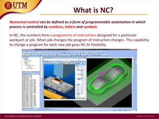
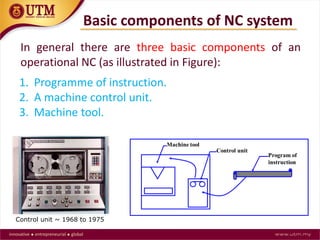
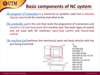
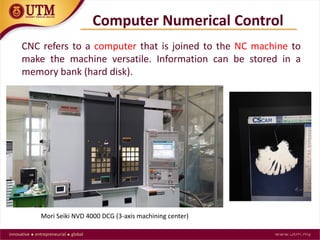
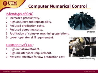
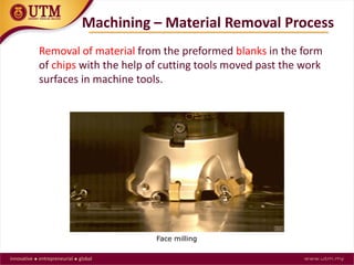
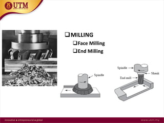
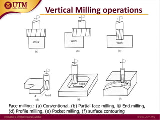
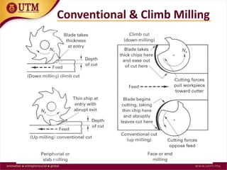
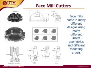
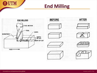
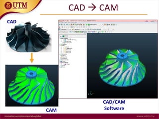
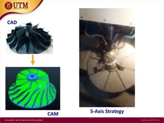
WELCOME TO UTM
TS. DR. MOHD AZLAN SUHAIMI
Department of Materials, Manufacturing and Industrial Engineering
Faculty of Mechanical Engineering
Universiti Teknologi Malaysia
INTRODUCTION CNC MILLING
Outline
1.NC vs CNC
2.Machining
3.Milling Processes
4.Machine coordinate system
5.CAD/CAM
What is NC?
Numerical control can be defined as a form of programmable automation in which
process is controlled by numbers, letters and symbols.
In NC, the numbers form a programme of instructions designed for a particular
workpart or job. When job changes the program of instruction changes. This capability
to change a program for each new job gives NC its flexibility.
Basic components of NC system
In general there are three basic components of an
operational NC (as illustrated in Figure):
1. Programme of instruction.
2. A machine control unit.
3. Machine tool.
Control unit ~ 1968 to 1975
Basic components of NC system
The program of instruction is a numerical or symbolic code that is detailed
step-by-step to tell the machine tool what to do.
The controller unit is the unit that reads the programme of instructions and
converts it to real movement of a machine tool. Two basic types of control
unit are used with NC machines: open-loop control and closed-loop
control.
The machine tool performs the mechanical work and deals directly with the
part being machined.
Computer Numerical Control
CNC refers to a computer that is joined to the NC machine to
make the machine versatile. Information can be stored in a
memory bank (hard disk).
Mori Seiki NVD 4000 DCG (3-axis machining center)
Advantages of CNC
1. Increased productivity.
2. High accuracy and repeatability.
3. Reduced production costs.
4. Reduced operating costs.
5. Facilitation of complex machining operations.
6. Lower operator skill requirement.
Limitations of CNC:
1. High initial investment.
2. High maintenance requirement.
3. Not cost-effective for low production cost.
Computer Numerical Control
Impeller
5-axis Machining
Removal of material from the preformed blanks in the form
of chips with the help of cutting tools moved past the work
surfaces in machine tools.
Machining – Material Removal Process
Face milling
Machining – Dilemma/Challenge
The high cutting force on a cutting edge
?
Machining – Dilemma/Challenge
Cutting zone temperatures
• A rotational workpart has a cylindrical or disk-like shape.
The characteristics operation that produces this geometry is
one in which a cutting tool removes material from rotating
workpart. e.g. turning and boring.
• A non-rotational (also called prismatic) workpart is block-
like or plate like. This geometry is achieved by linear motions
of the workpart, combined with either rotating or linear tool
motion.
Work-part/Workpiece
Rotational Non-rotational
A
B
Machining Processes Classification
MILLING
Horizontal Milling
Vertical Milling
Types of Milling
Some of the basic types of milling cutters and milling operations.
• Milling is a metal removal
process by means of using a
rotating cutter having one or
more cutting teeth as
illustrated in the figure below.
• Cutting action is carried out by
feeding the workpiece against
the rotating cutter. Thus, the
spindle speed, the table feed,
the depth of cut, and the
rotating direction of the cutter
become the main parameters
of the process. Good results
can only be achieved with a
well balanced settings of
these parameters.
Milling Process
The Horizontal Milling Machine
• Also called peripheral milling. The axis of cutter
rotation is parallel to the workpiece surface to be
machined
• Produces flat surfaces, contoured, or shaped surfaces
(grooves, gears, etc)
Slab Milling
• Helical cutters are preferred over straight cutters –
lower load on the tooth, cutting progressively, resulting
in a smoother operation, reducing tool forces and
chatter (vibration).
Slab Milling Cutters
Slab Milling Process
• Conventional or up-cut milling
• The cutter rotates in a direction
opposite to the table feed as
illustrated in the figure. It is
conventionally used in most milling.
• Smooth process with maximum chip
thickness is at the end of cut.
• Tooth engagement is not a function of
surface characteristics –
contamination or scale on the surface
does not affect tool life.
• Tendency for the tool to chatter
• Tendency for the workpiece to be
pulled upward – needs proper
clamping
Slab Milling Process
• Climb or down-cut milling
• The cutter rotates in the same direction as
the table feed as illustrated in the figure.
• Cutting starts at the surface of the
workpiece, where the chip is at its
thickest- high impact forces, needs a rigid
set-up.
• Downward component of the cutting
forces holds the workpiece in place.
• Since chips pile up behind the cutter, tool
life can be increased by as much as 50%
• Chips are less likely to be carried by the
tooth, reducing marring of the machined
surface – improved surface finish
• Chips fall behind the cutter resulting in
faster and easier chip removal
• Conventional milling (up milling) is recommended for
milling castings or forgings with very rough surfaces
due to sand or scale and should be used in all
applications.
• Down milling can be used in most milling
applications, especially for difficult-to-cut materials
such as Titanium, Inconel, Stainless steel.
Conventional or climb milling
Various types of Slab Milling Cutters
Mounting a milling cutter on an arbor for use on a horizontal
milling machine.
Arbor
MILLING
Face Milling
End Milling
• Rough and finish
machining.
• Complex shapes.
• Pockets.
• Holes (drilling and
boring).
• Profiles.
• Surfaces.
• Keyways and slots.
Vertical Milling Machine
Face milling : (a) Conventional, (b) Partial face milling, © End milling,
(d) Profile milling, (e) Pocket milling, (f) surface contouring
Vertical Milling operations
Conventional & Climb Milling
Face mills
come in many
different
designs using
many
different
insert
geometries
and different
mounting
arbors
Face Mill Cutters
End Milling
End Milling Cutters
General dimensions
Geometry - cutting angles
• End Milling Cutters – designed to
mill slots, keyways, pockets, radii
and other wide variety of shapes.
• Cutting edges are on the
circumference and end. They
have straight or helical flutes, two
flute or multi-flute, straight or
tapered shanks.
End Milling Cutters
•The direction of each finger
represents the positive direction of
motion.
•The axis of the main spindle is
always Z, and the positive
direction is into the spindle.
•On a mill the longest travel slide
is designated the X axis and is
always perpendicular to the Z axis.
•your middle finger, the forefinger
represents the Y axis.
•The base of your fingers is the
start point or (X0, Y0, Z0).
Machine Coordinate System
The right-hand rule for determining the correct axis on a
CNC machine may also be used to determine the
clockwise rotary motion about X, Y, and Z.
•To determine the positive, or clockwise, direction about
an axis, close your hand with the thumb pointing out.
•The thumb may represent the X, Y, or Z direction and the
curl of the fingers may represent the clockwise, or
positive, rotation about each axis.
•These are known as A, B, and C and represent the rotary
motions about X, Y, and Z, respectively.
Rotary Motion Designation
On this gantry mill the spindle travels along the X Axis. The
travel direction of the table designates the Y Axis. The Z Axis is
designated by the stationary vertical column.
Axis and motion nomenclature – CNC mill
On most CNC lathes the Z Axis is parallel to
the spindle and longer than the X Axis.
Axis and motion nomenclature – CNC lathe
Axis and motion nomenclature – 5-Axis
On this five-axis horizontal contour milling machine, note the
orientation of the X and Y axes in relation to the Z Axis. The
rotary axes for both the X and Y axes are designated by the A and
B rotary tables.
37
1.1 CAD (Computer Aided Design)
Definition:
Any design activity that involves the use of
the computer to create, modify or
document an engineering design.
(Groover M.P., Automation, Production Systems &
Computer Integrated Manufacturing, Prentice-Hall, 1987)
CAD
Part of technical drawing
MMT 39
CAD
40
1.2 CAM (COMPUTER AIDED
MANUFACTURING)
Classifications of manufacture which are computer aided to a
significant degree so as to come under the heading of
CAM are:
– Technological planning of the approach and detailed methods of
manufacture.
– Production scheduling and control of the product’s manufacture.
– Automated and computer controlled manufacture.
CAM
CAD  CAM
CAD/CAM
Software
CAD
CAM
5-Axis Strategy
CAD
CAM
Thank you

CNC-Mill-KV-Azlan-1.pdf

  • 1.
    WELCOME TO UTM TS.DR. MOHD AZLAN SUHAIMI Department of Materials, Manufacturing and Industrial Engineering Faculty of Mechanical Engineering Universiti Teknologi Malaysia INTRODUCTION CNC MILLING
  • 2.
    Outline 1.NC vs CNC 2.Machining 3.MillingProcesses 4.Machine coordinate system 5.CAD/CAM
  • 3.
    What is NC? Numericalcontrol can be defined as a form of programmable automation in which process is controlled by numbers, letters and symbols. In NC, the numbers form a programme of instructions designed for a particular workpart or job. When job changes the program of instruction changes. This capability to change a program for each new job gives NC its flexibility.
  • 4.
    Basic components ofNC system In general there are three basic components of an operational NC (as illustrated in Figure): 1. Programme of instruction. 2. A machine control unit. 3. Machine tool. Control unit ~ 1968 to 1975
  • 5.
    Basic components ofNC system The program of instruction is a numerical or symbolic code that is detailed step-by-step to tell the machine tool what to do. The controller unit is the unit that reads the programme of instructions and converts it to real movement of a machine tool. Two basic types of control unit are used with NC machines: open-loop control and closed-loop control. The machine tool performs the mechanical work and deals directly with the part being machined.
  • 6.
    Computer Numerical Control CNCrefers to a computer that is joined to the NC machine to make the machine versatile. Information can be stored in a memory bank (hard disk). Mori Seiki NVD 4000 DCG (3-axis machining center)
  • 7.
    Advantages of CNC 1.Increased productivity. 2. High accuracy and repeatability. 3. Reduced production costs. 4. Reduced operating costs. 5. Facilitation of complex machining operations. 6. Lower operator skill requirement. Limitations of CNC: 1. High initial investment. 2. High maintenance requirement. 3. Not cost-effective for low production cost. Computer Numerical Control Impeller 5-axis Machining
  • 8.
    Removal of materialfrom the preformed blanks in the form of chips with the help of cutting tools moved past the work surfaces in machine tools. Machining – Material Removal Process Face milling
  • 9.
    Machining – Dilemma/Challenge Thehigh cutting force on a cutting edge ?
  • 10.
  • 11.
    • A rotationalworkpart has a cylindrical or disk-like shape. The characteristics operation that produces this geometry is one in which a cutting tool removes material from rotating workpart. e.g. turning and boring. • A non-rotational (also called prismatic) workpart is block- like or plate like. This geometry is achieved by linear motions of the workpart, combined with either rotating or linear tool motion. Work-part/Workpiece Rotational Non-rotational A B
  • 12.
  • 13.
    MILLING Horizontal Milling Vertical Milling Typesof Milling Some of the basic types of milling cutters and milling operations.
  • 14.
    • Milling isa metal removal process by means of using a rotating cutter having one or more cutting teeth as illustrated in the figure below. • Cutting action is carried out by feeding the workpiece against the rotating cutter. Thus, the spindle speed, the table feed, the depth of cut, and the rotating direction of the cutter become the main parameters of the process. Good results can only be achieved with a well balanced settings of these parameters. Milling Process
  • 15.
  • 16.
    • Also calledperipheral milling. The axis of cutter rotation is parallel to the workpiece surface to be machined • Produces flat surfaces, contoured, or shaped surfaces (grooves, gears, etc) Slab Milling
  • 17.
    • Helical cuttersare preferred over straight cutters – lower load on the tooth, cutting progressively, resulting in a smoother operation, reducing tool forces and chatter (vibration). Slab Milling Cutters
  • 18.
    Slab Milling Process •Conventional or up-cut milling • The cutter rotates in a direction opposite to the table feed as illustrated in the figure. It is conventionally used in most milling. • Smooth process with maximum chip thickness is at the end of cut. • Tooth engagement is not a function of surface characteristics – contamination or scale on the surface does not affect tool life. • Tendency for the tool to chatter • Tendency for the workpiece to be pulled upward – needs proper clamping
  • 19.
    Slab Milling Process •Climb or down-cut milling • The cutter rotates in the same direction as the table feed as illustrated in the figure. • Cutting starts at the surface of the workpiece, where the chip is at its thickest- high impact forces, needs a rigid set-up. • Downward component of the cutting forces holds the workpiece in place. • Since chips pile up behind the cutter, tool life can be increased by as much as 50% • Chips are less likely to be carried by the tooth, reducing marring of the machined surface – improved surface finish • Chips fall behind the cutter resulting in faster and easier chip removal
  • 20.
    • Conventional milling(up milling) is recommended for milling castings or forgings with very rough surfaces due to sand or scale and should be used in all applications. • Down milling can be used in most milling applications, especially for difficult-to-cut materials such as Titanium, Inconel, Stainless steel. Conventional or climb milling
  • 21.
    Various types ofSlab Milling Cutters
  • 22.
    Mounting a millingcutter on an arbor for use on a horizontal milling machine. Arbor
  • 23.
  • 24.
    • Rough andfinish machining. • Complex shapes. • Pockets. • Holes (drilling and boring). • Profiles. • Surfaces. • Keyways and slots. Vertical Milling Machine
  • 25.
    Face milling :(a) Conventional, (b) Partial face milling, © End milling, (d) Profile milling, (e) Pocket milling, (f) surface contouring Vertical Milling operations
  • 26.
  • 27.
    Face mills come inmany different designs using many different insert geometries and different mounting arbors Face Mill Cutters
  • 28.
  • 29.
    End Milling Cutters Generaldimensions Geometry - cutting angles
  • 30.
    • End MillingCutters – designed to mill slots, keyways, pockets, radii and other wide variety of shapes. • Cutting edges are on the circumference and end. They have straight or helical flutes, two flute or multi-flute, straight or tapered shanks. End Milling Cutters
  • 31.
    •The direction ofeach finger represents the positive direction of motion. •The axis of the main spindle is always Z, and the positive direction is into the spindle. •On a mill the longest travel slide is designated the X axis and is always perpendicular to the Z axis. •your middle finger, the forefinger represents the Y axis. •The base of your fingers is the start point or (X0, Y0, Z0). Machine Coordinate System
  • 32.
    The right-hand rulefor determining the correct axis on a CNC machine may also be used to determine the clockwise rotary motion about X, Y, and Z. •To determine the positive, or clockwise, direction about an axis, close your hand with the thumb pointing out. •The thumb may represent the X, Y, or Z direction and the curl of the fingers may represent the clockwise, or positive, rotation about each axis. •These are known as A, B, and C and represent the rotary motions about X, Y, and Z, respectively. Rotary Motion Designation
  • 34.
    On this gantrymill the spindle travels along the X Axis. The travel direction of the table designates the Y Axis. The Z Axis is designated by the stationary vertical column. Axis and motion nomenclature – CNC mill
  • 35.
    On most CNClathes the Z Axis is parallel to the spindle and longer than the X Axis. Axis and motion nomenclature – CNC lathe
  • 36.
    Axis and motionnomenclature – 5-Axis On this five-axis horizontal contour milling machine, note the orientation of the X and Y axes in relation to the Z Axis. The rotary axes for both the X and Y axes are designated by the A and B rotary tables.
  • 37.
    37 1.1 CAD (ComputerAided Design) Definition: Any design activity that involves the use of the computer to create, modify or document an engineering design. (Groover M.P., Automation, Production Systems & Computer Integrated Manufacturing, Prentice-Hall, 1987) CAD
  • 38.
  • 39.
  • 40.
    40 1.2 CAM (COMPUTERAIDED MANUFACTURING) Classifications of manufacture which are computer aided to a significant degree so as to come under the heading of CAM are: – Technological planning of the approach and detailed methods of manufacture. – Production scheduling and control of the product’s manufacture. – Automated and computer controlled manufacture. CAM
  • 41.
  • 42.
  • 43.