
Downloaded 101 times
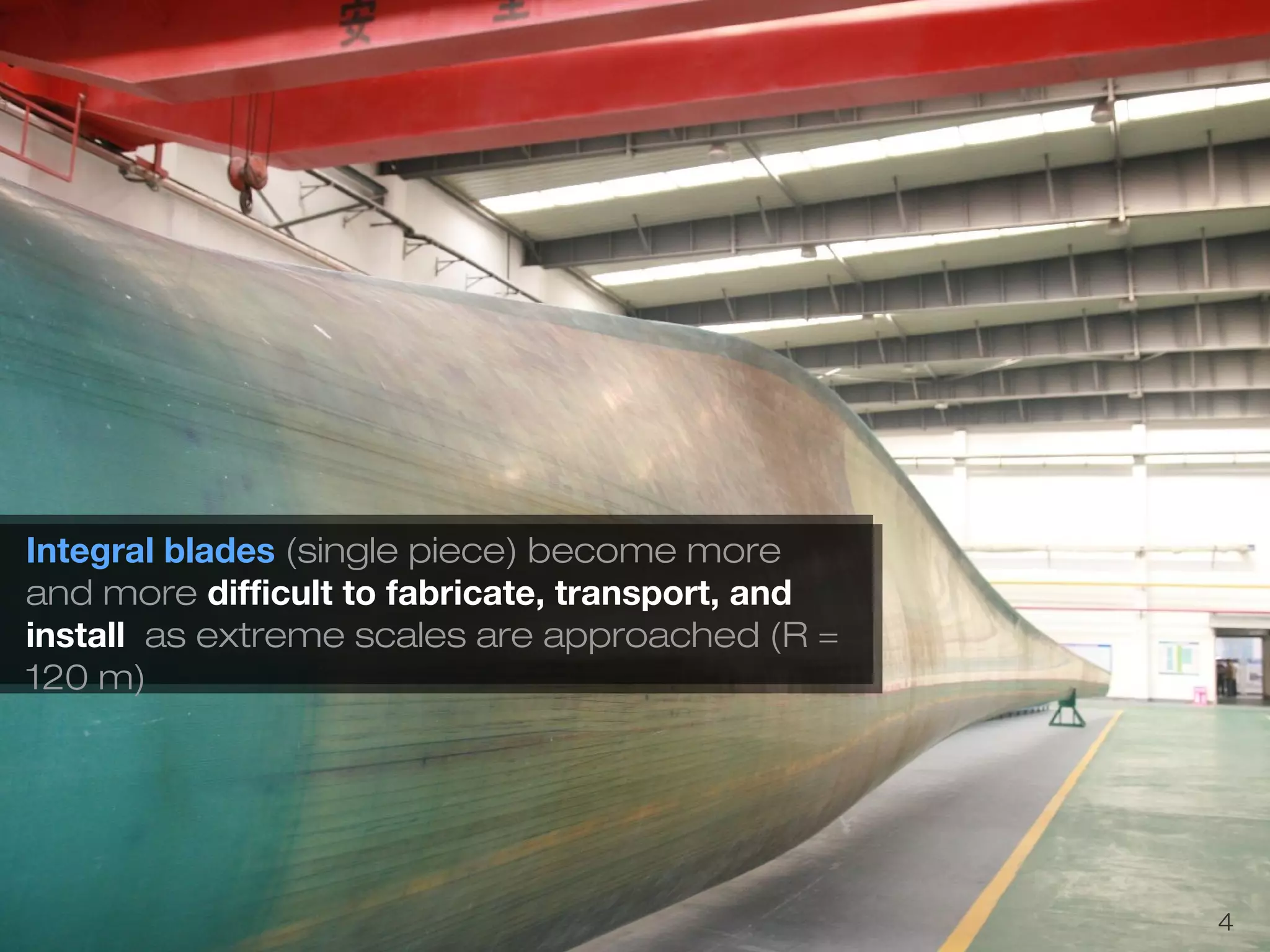
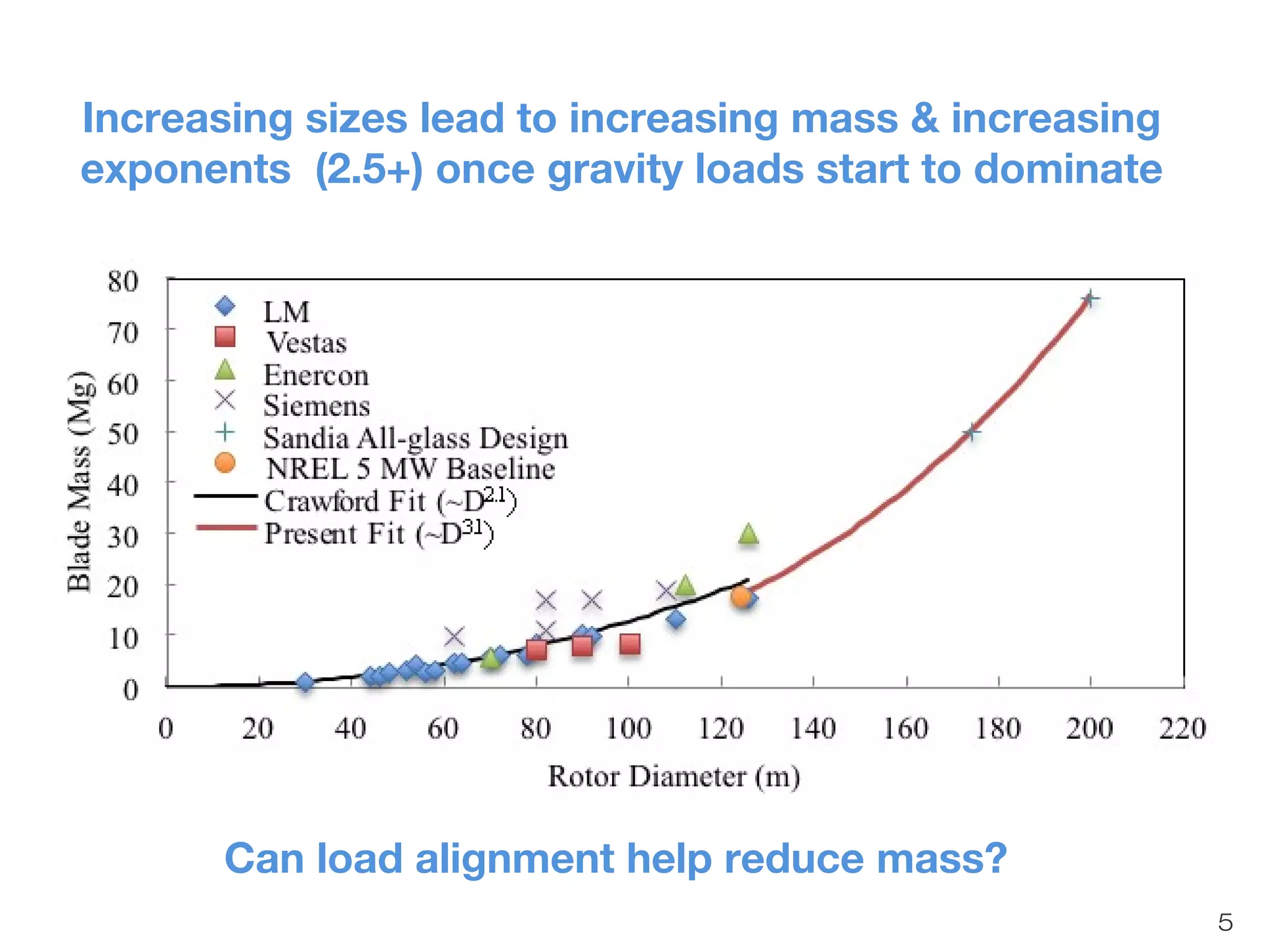

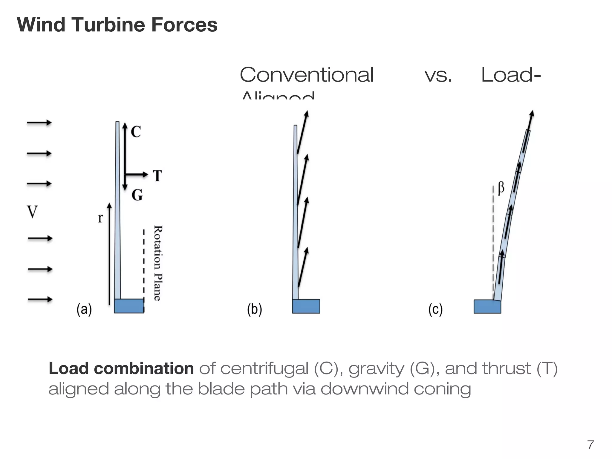
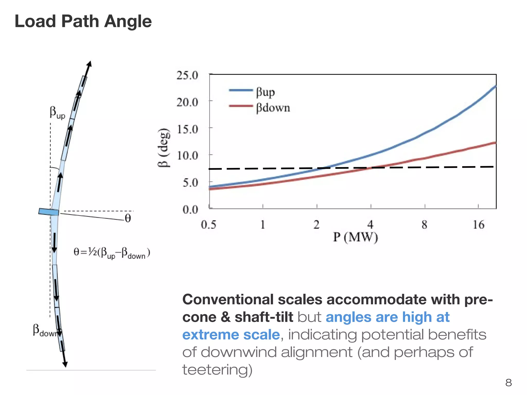


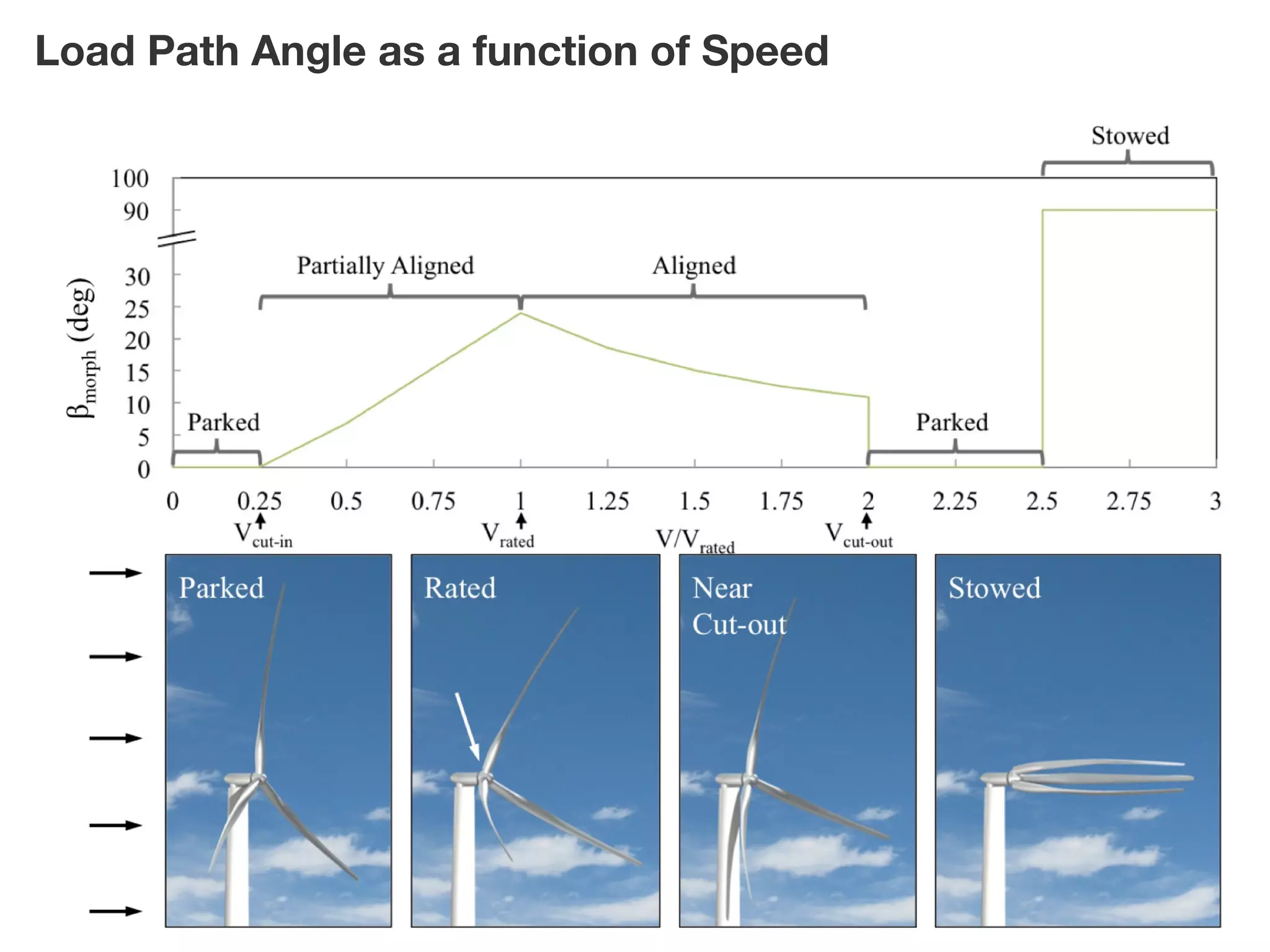
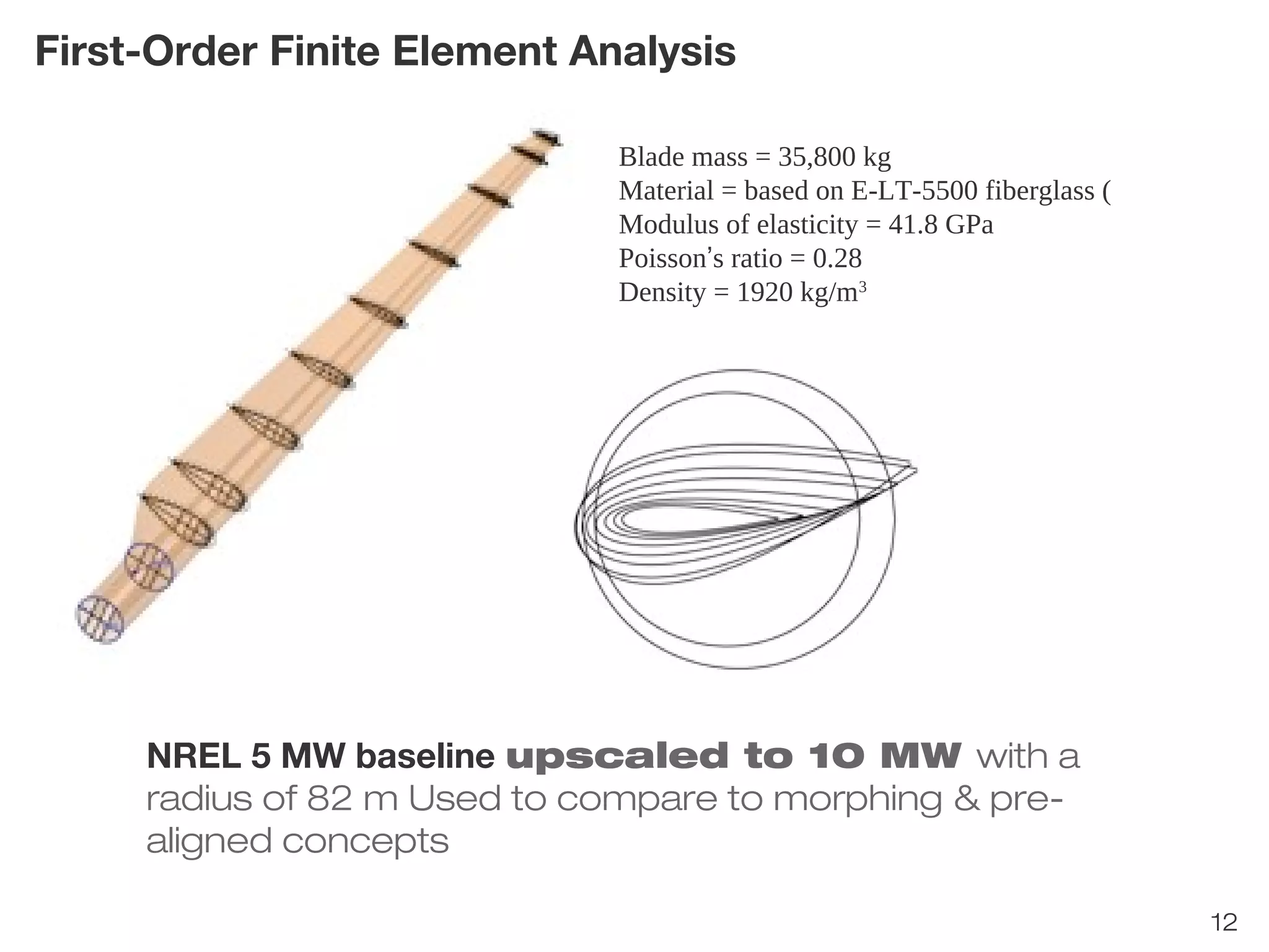

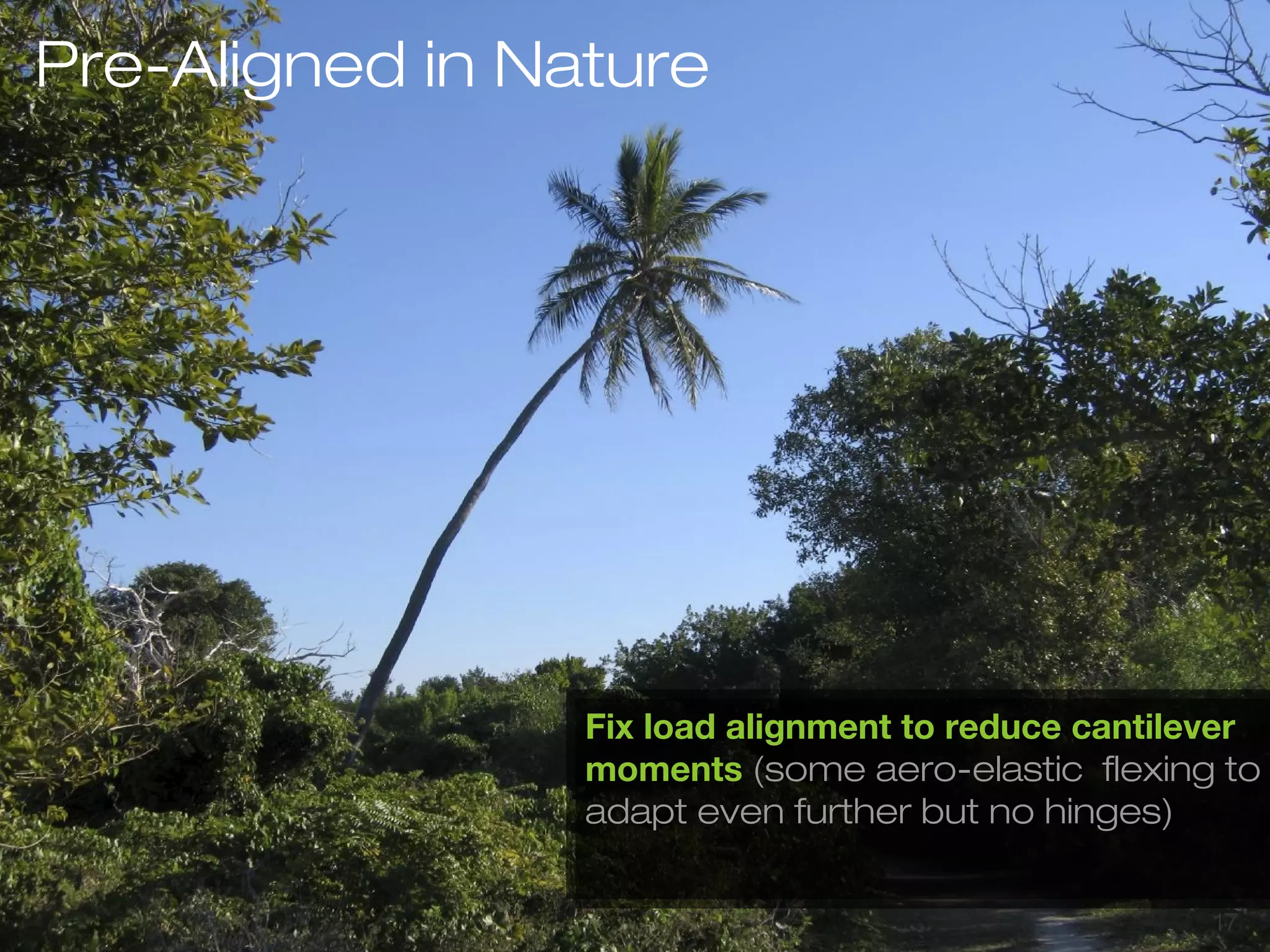
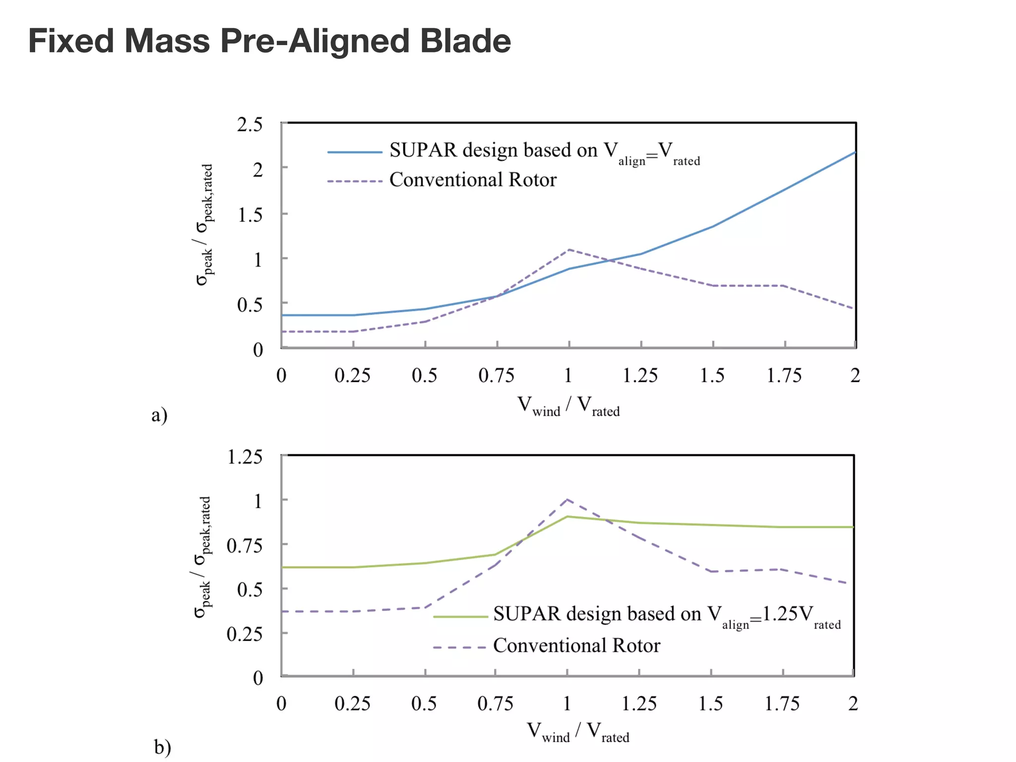

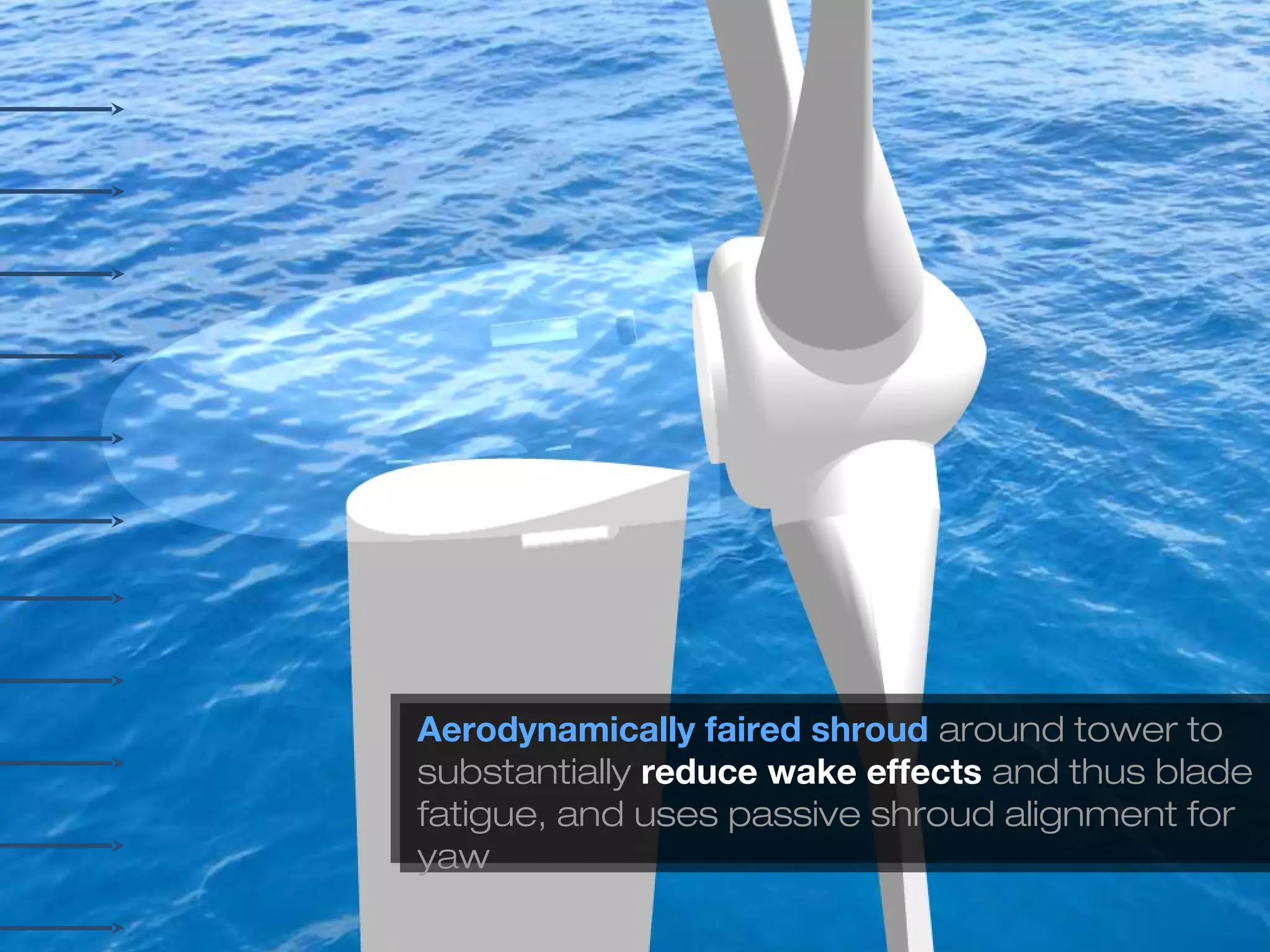
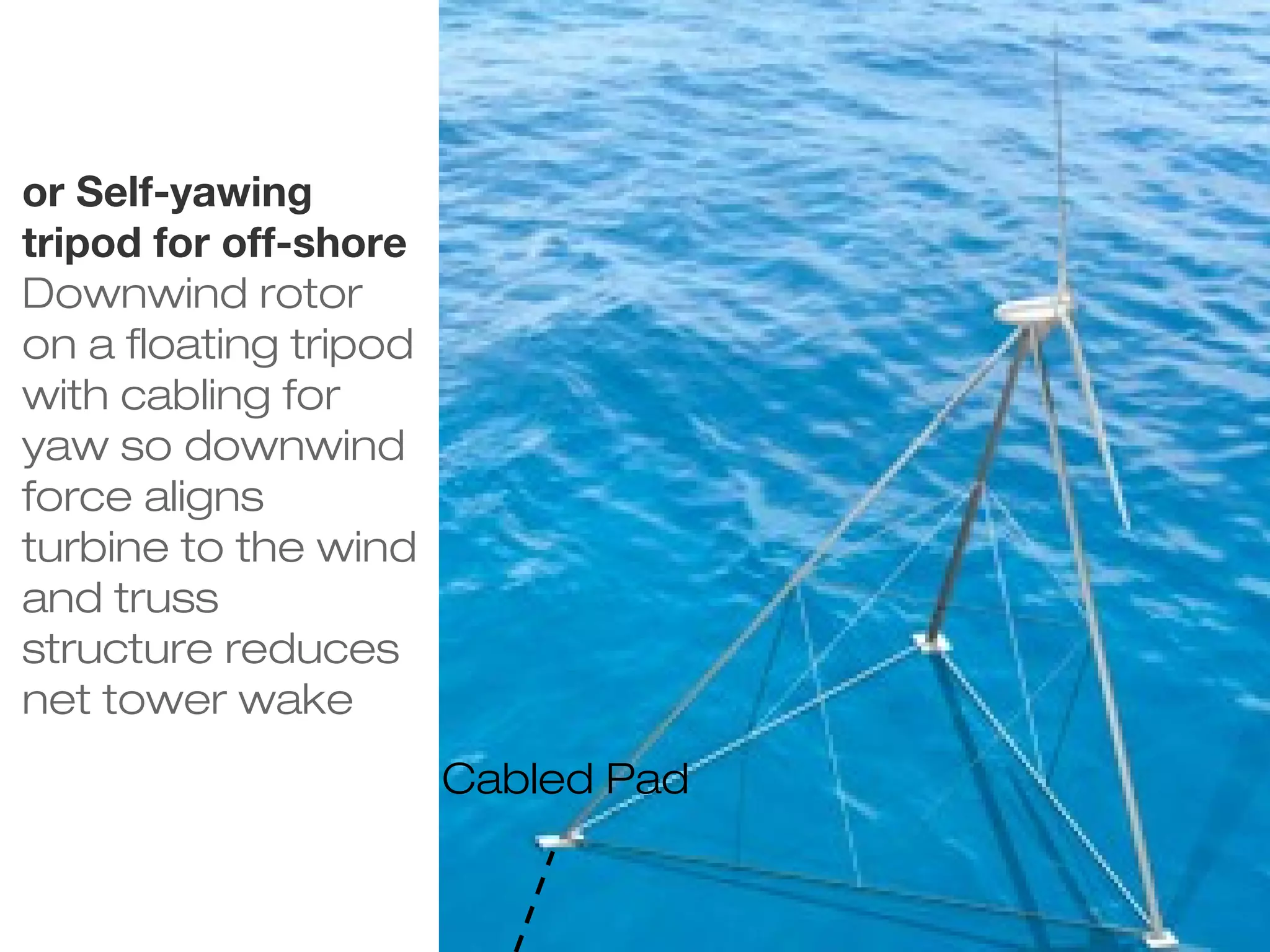
The document discusses potential benefits of downwind force-aligned rotors for extreme-scale offshore wind turbines. It describes how load alignment through concepts like morphing blades and pre-aligned blade segments could help reduce structural loads and mass. Steady-state analysis shows morphing could allow major reductions in blade and tower mass. Pre-alignment offers load savings with less complexity than morphing. Aerodynamic shrouds around the tower also help reduce wake effects. More analysis is still needed to determine the feasibility and benefits of these force-aligned downwind concepts.


