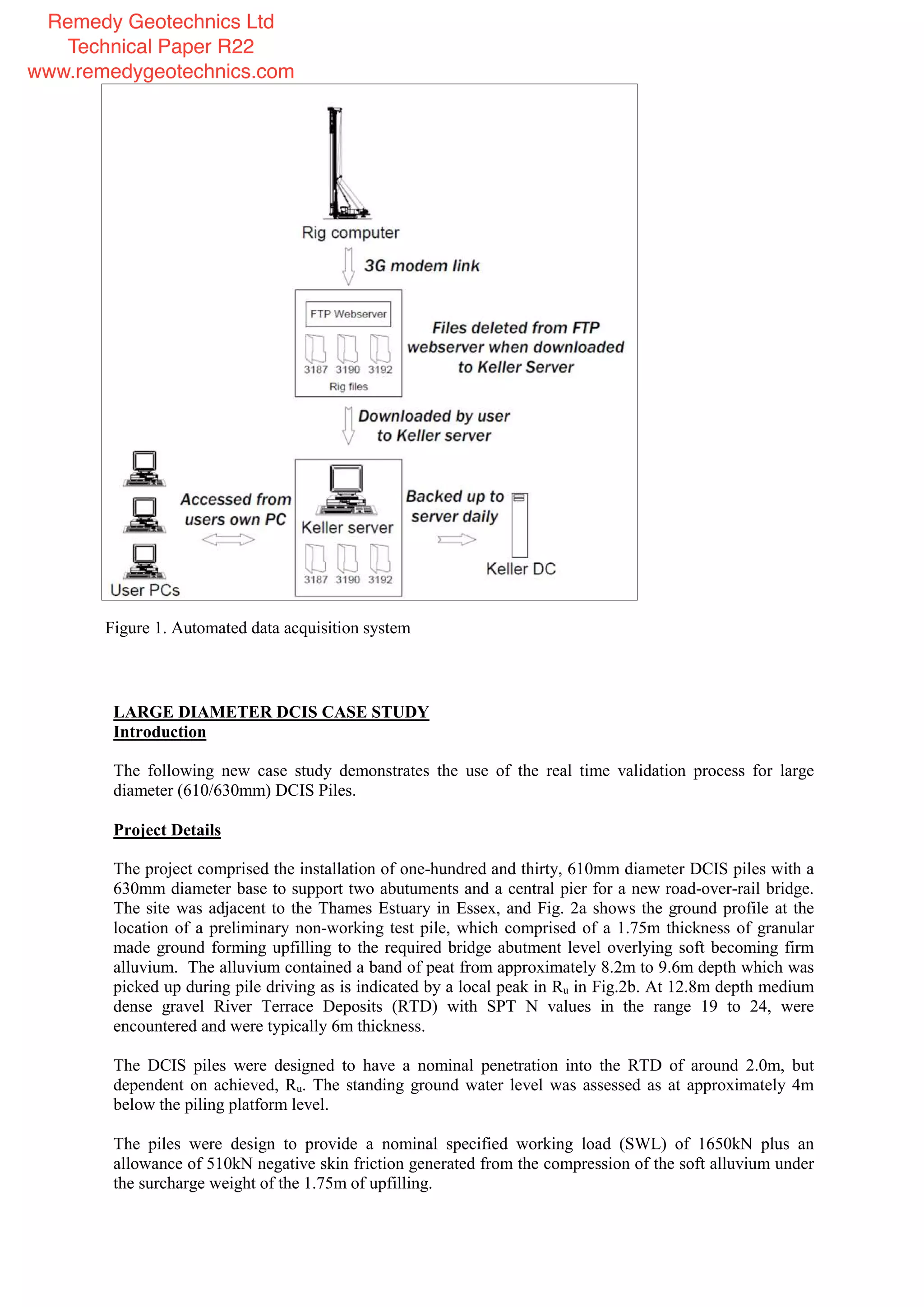
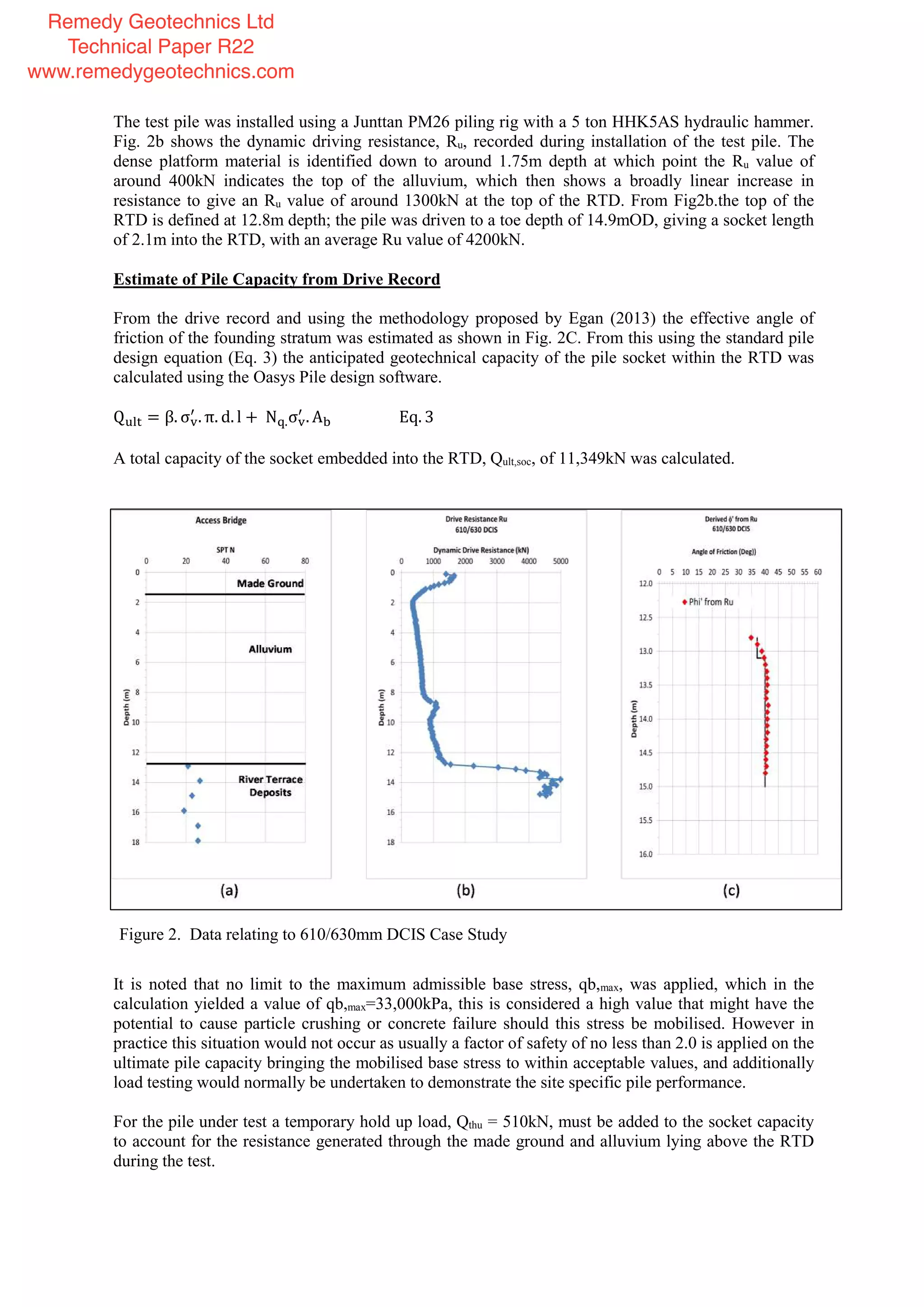
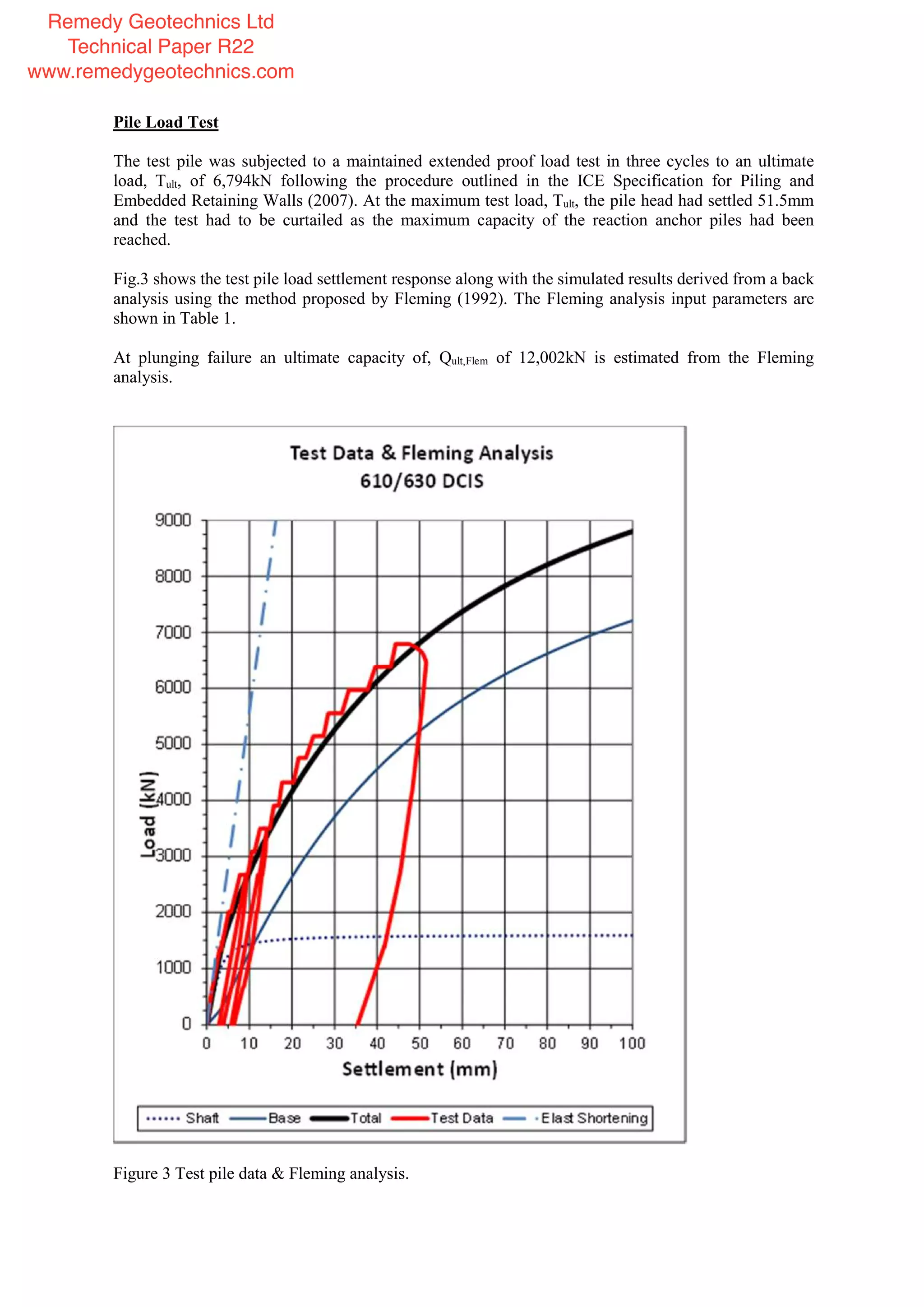
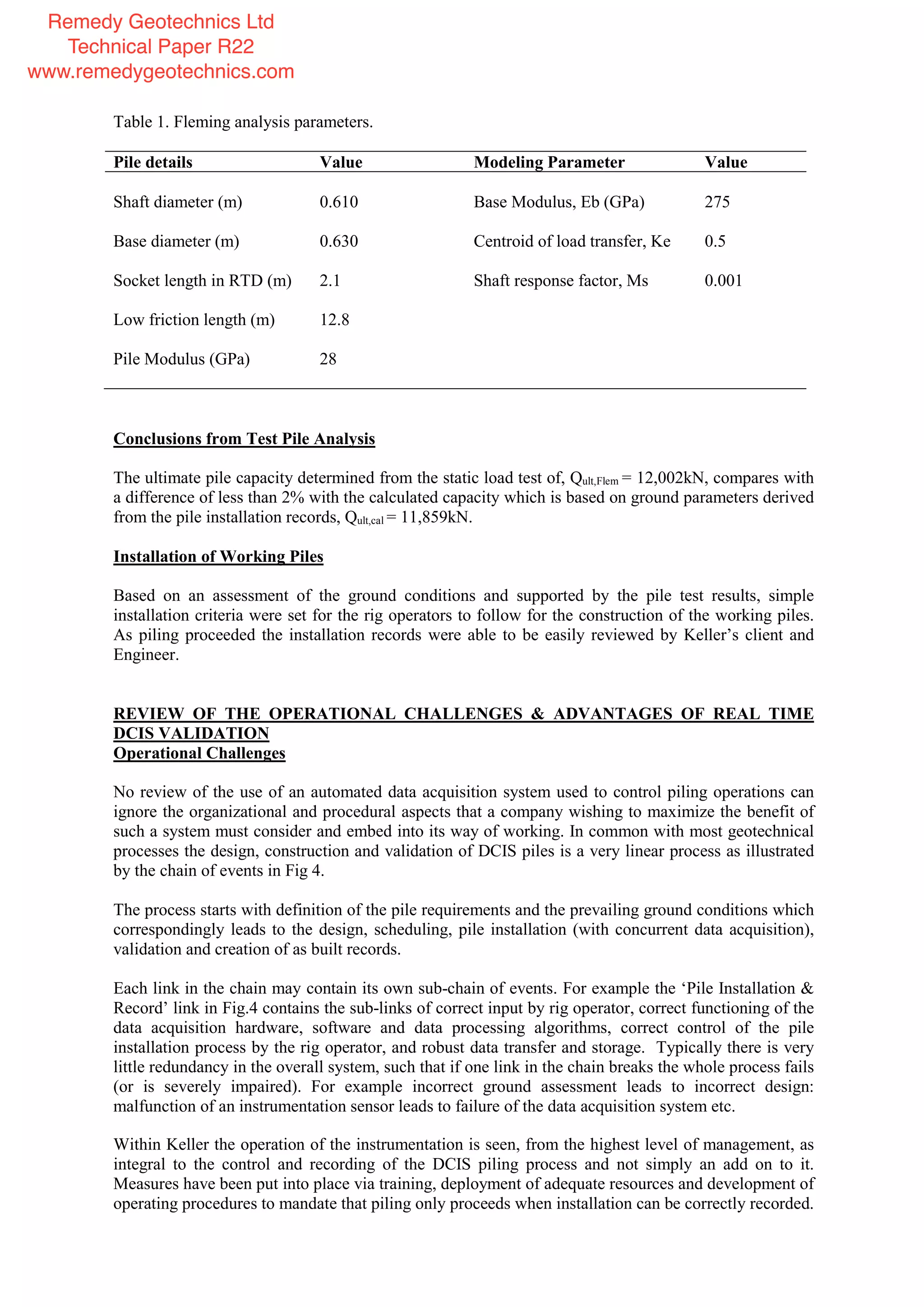
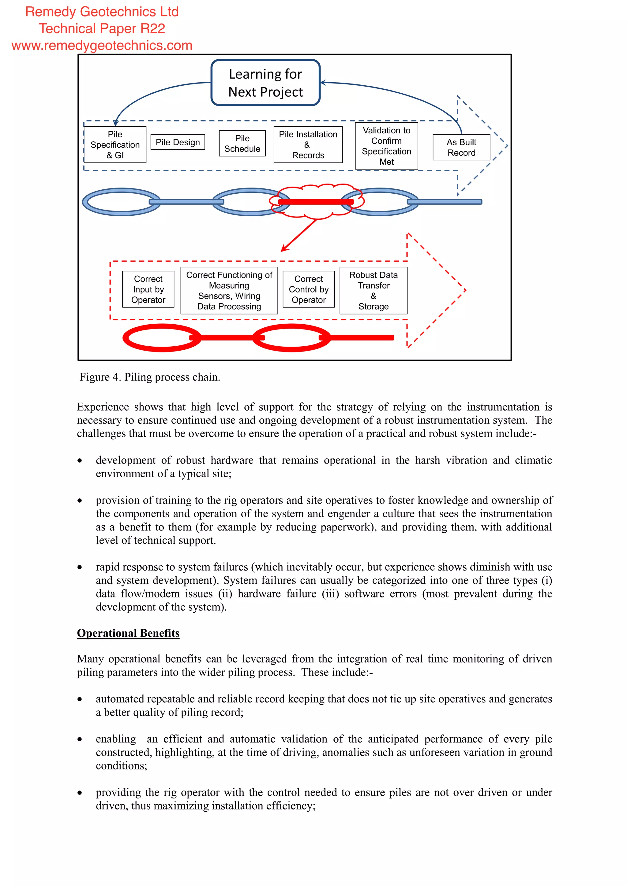
SlideShare a Scribd company logo
1 of 10
Download to read offline
REAL TIME VALIDATION OF DRIVEN CAST IN-SITU PILES
Derek Egan, Keller UK, Oxford Road, Ryton on Dunsmore, Coventry.
Abstract Construction clients want their foundation solutions to be right first time, every time; but it
is often the geotechnical contractor who carries the most risk in achieving this. Robust validation to
ensure that the installed geotechnical product is appropriate for the encountered ground conditions,
will perform as required and be correctly measured for payment and record purposes is very important
to minimise the contractor’s and the client’s risk. This paper outlines the development and operation
of a robust real-time installation monitoring system which controls and validates the installation of
driven cast in-situ (DCIS) piling. Using state of the art information technology the system allows the
design engineer to interrogate the data acquired from the piling rig via his computer as the piles are
completed. The use of the validation process, where data acquired during the driving of DCIS piles
can be processed to estimate the finished pile performance, will be explained with reference to a new
case study on large diameter DCIS piles. Examples of the routine use of the system will be presented
to illustrate how automated monitoring of installation parameters can be used to raise the standard of
reliability, efficiency and sustainability on piling projects. The conclusions to the paper will cover the
key features and operational challenges characterising real-time monitoring of the execution of
geotechnical works as developed from a number of years of experience of using a rig based data
acquisition instrumentation system.
.
INTRODUCTION
Driven Cast In-Situ (DCIS) piles have a long and successful history of use worldwide. The process,
where a temporary steel drive tube, sealed at the bottom with a sacrificial base plate, is driven into the
ground and filled with concrete before the tube is withdrawn, is well known (BS EN 12699, 2001 and
Egan, 2013). Examples of large structures supported on DCIS piles installed by Keller UK include the
Millennium Dome (now the O2 Arena) and the 2012 Olympic stadium in London.
In recent times advances in piling rig instrumentation and telecommunications have enabled a new
level of sophistication in the recording of installation parameters and the validation of pile
performance. It is now possible to embed these features into the DCIS design and installation process
which has improved the quality and efficiency of DCIS piling.
This paper summarises the development and operation of a real time data acquisition and processing
system for DCIS piling, but which is equally applicable to other forms of driven piling (for example
concrete precast piling).
The Drivers for Development
The drivers for the development of an automated data acquisition and processing system include:-
Utilization of existing technology to modernize and increase efficiency and reliability of the
recording of pile installation parameters such as driven length, set, number of hammer blows,
hammer drop height and details of the pile section size. Historically these data were recorded in
site notebooks or in similar paper format, which in inclement weather was a challenge in itself.
Certain aspects of the manual recording approach suffer from an inherent error budget, for
example measurement (or estimation) of hammer drop height and set, due to a variety of reasons
including the environment, the weather and the individual taking the reading. Repeatable
parameter measurement using electronic instrumentation improves considerably the consistency
and reliability of the data acquired.
Remedy Geotechnics Ltd
Technical Paper R22
www.remedygeotechnics.com
Reducing the time period between the completion of a pile and availability of the installation data
to interested stakeholders (project managers, designers etc.).
Development, with time, of an historic data base of easily accessible installation information
acquired from numerous projects in different locations which can be used for reference when
designing future schemes.
Of course the advances described in this paper should be seen in the context of the use of dynamic
pile driving formulae that have been used on pre-formed piles for many decades. However widespread
the use of set calculations their applicability (and reliability) for driven cast in situ piling, where the
drive tube driven into the ground is removed and replaced by cast in place concrete, has received little
attention in the literature.
DESCRIPTION OF THE SYSTEM
Monitored Parameters
The key parameters required for complete description of an installed DCIS pile are:-
Pile location, geometrical dimensions (drive tube and shoe diameter and length) etc.
hammer impact energy (historically defined by hammer mass, drop height with an allowance for
energy losses);
penetration resistance (historically described as the set and measured in blows per unit of
penetration).
The system described here records the pile reference number and geometry, hammer mass, number of
hammer blows and the hammer velocity for each blow, the depth of penetration of the pile, the
penetration per hammer blow, and time.
Data Processing
The monitored parameters must be processed to give them a real-world meaning. The key parameters
of interest are time, pile length, pile diameter, and drive resistance. From knowledge of the prevailing
ground conditions the performance of the completed pile can then be predicted and validated against
the contractual requirements.
From the above list the calculation of the dynamic drive resistance, Ru, and correlation to the load
settlement performance of the completed pile is the most valuable aspect of the system described here.
Calculation of Dynamic Drive Resistance
Dynamic drive resistance, Ru, is the correct term that should be used to describe the resisting force the
pile must overcome to be able to penetrate into the ground.
The term set, although routinely used, should be avoided. Fellenius (1999) describes set as the
penetration for one blow, sometimes a series of blows. On its own the set tells us nothing of the
ground resistance until the energy imparted to the pile, from the hammer, minus any losses, is known,
and hence, because it is incomplete, the term set will be not be used further.
The term dynamic drive desistance Ru, defined as the energy required to advance the pile a unit length
into the ground, (measured in kN) provides a much more satisfactory parameter to work with.
From the recorded installation parameters the tube drive resistance with depth is calculated, where Ru
is the dynamic drive resistance, N is the hammer energy, s is the rate of tube advancement per
Remedy Geotechnics Ltd
Technical Paper R22
www.remedygeotechnics.com
hammer blow and c is the elastic compression of the tube.
=
− 2
Eq. 1
The factors f1 and f2 are hammer and energy transfer efficiency factors. In practice it is difficult to
separate these two factors out. Extensive dynamic testing during drive tube installation has enabled
the energy losses when driving DCIS piles to be quantified.
The elastic compression of the drive tube is calculated using equation 2 which is based on the Danish
pile driving formula, and where N is the hammer energy, L is the tube length, A is the cross sectional
area of the tube and E the elastic modulus.
=
2
Eq. 2
As a pile is driven these data are recorded by the rig computer, processed and displayed on a screen as
a profile of drive resistance, Ru, with depth. The rig operator then controls the installation of the pile
to achieve the predefined installation criteria which are set to ensure the required pile performance
under load is achieved for the prevailing ground conditions.
The method to define the installation criteria has been refined over a number of years on the back of
extensive site testing using instrumented and non-instrumented piles (Flynn et al., 2012, Flynn et al.,
2013, and Egan, 2013)
Data Transfer
Once acquired the data for the installation of a given pile it is transferred through to the Keller
computer servers as shown in Fig. 1. Not only is a systematic, robustly archived, database of piling
records established, but the data are instantly available to the engineer in their office via their
computer. The acquired data may be summarised graphically or interrogated within a spreadsheet.
USE OF INSTALLATION DATA TO VALIDATE PILE PERFORMANCE
Introduction
The driving of a pile in many ways resembles the cone penetration test (CPT) and/or the standard
penetration test (SPT), both which allow correlation to soil properties. Therefore it is reasonable to
suppose that, with reliable and repeatable data acquisition of pile driving data, a similar approach to
the assessment of soil properties and hence pile performance could be undertaken following the
driving of a pile.
Egan (2013) discusses how this approach can be adopted and presents a case study on an 11.0m long
DCIS pile of nominal 340mm diameter at a site in Erith, Kent subject to a load test to failure. In the
load test a plunging failure of the pile under an applied load, Qult,test of 1947kN at a displacement of
45mm was observed.
The ultimate pile capacity, Qult,cal, calculated from the drive record was 2060kN, demonstrating the
observed and calculated pile capacities were within 6%, and well within the confidence level expected
for a geotechnical pile design.
Remedy Geotechnics Ltd
Technical Paper R22
www.remedygeotechnics.com
LARGE DIAMETER DCIS CASE STUDY
Introduction
The following new case study demonstrates the use of the real time validation process for large
diameter (610/630mm) DCIS Piles.
Project Details
The project comprised the installation of one-hundred and thirty, 610mm diameter DCIS piles with a
630mm diameter base to support two abutuments and a central pier for a new road-over-rail bridge.
The site was adjacent to the Thames Estuary in Essex, and Fig. 2a shows the ground profile at the
location of a preliminary non-working test pile, which comprised of a 1.75m thickness of granular
made ground forming upfilling to the required bridge abutment level overlying soft becoming firm
alluvium. The alluvium contained a band of peat from approximately 8.2m to 9.6m depth which was
picked up during pile driving as is indicated by a local peak in Ru in Fig.2b. At 12.8m depth medium
dense gravel River Terrace Deposits (RTD) with SPT N values in the range 19 to 24, were
encountered and were typically 6m thickness.
The DCIS piles were designed to have a nominal penetration into the RTD of around 2.0m, but
dependent on achieved, Ru. The standing ground water level was assessed as at approximately 4m
below the piling platform level.
The piles were design to provide a nominal specified working load (SWL) of 1650kN plus an
allowance of 510kN negative skin friction generated from the compression of the soft alluvium under
the surcharge weight of the 1.75m of upfilling.
Figure 1. Automated data acquisition system
Remedy Geotechnics Ltd
Technical Paper R22
www.remedygeotechnics.com
The test pile was installed using a Junttan PM26 piling rig with a 5 ton HHK5AS hydraulic hammer.
Fig. 2b shows the dynamic driving resistance, Ru, recorded during installation of the test pile. The
dense platform material is identified down to around 1.75m depth at which point the Ru value of
around 400kN indicates the top of the alluvium, which then shows a broadly linear increase in
resistance to give an Ru value of around 1300kN at the top of the RTD. From Fig2b.the top of the
RTD is defined at 12.8m depth; the pile was driven to a toe depth of 14.9mOD, giving a socket length
of 2.1m into the RTD, with an average Ru value of 4200kN.
Estimate of Pile Capacity from Drive Record
From the drive record and using the methodology proposed by Egan (2013) the effective angle of
friction of the founding stratum was estimated as shown in Fig. 2C. From this using the standard pile
design equation (Eq. 3) the anticipated geotechnical capacity of the pile socket within the RTD was
calculated using the Oasys Pile design software.
Q = β. σ . π. d. l + N .σ . A Eq. 3
A total capacity of the socket embedded into the RTD, Qult,soc, of 11,349kN was calculated.
It is noted that no limit to the maximum admissible base stress, qb,max, was applied, which in the
calculation yielded a value of qb,max=33,000kPa, this is considered a high value that might have the
potential to cause particle crushing or concrete failure should this stress be mobilised. However in
practice this situation would not occur as usually a factor of safety of no less than 2.0 is applied on the
ultimate pile capacity bringing the mobilised base stress to within acceptable values, and additionally
load testing would normally be undertaken to demonstrate the site specific pile performance.
For the pile under test a temporary hold up load, Qthu = 510kN, must be added to the socket capacity
to account for the resistance generated through the made ground and alluvium lying above the RTD
during the test.
Figure 2. Data relating to 610/630mm DCIS Case Study
Remedy Geotechnics Ltd
Technical Paper R22
www.remedygeotechnics.com
Pile Load Test
The test pile was subjected to a maintained extended proof load test in three cycles to an ultimate
load, Tult, of 6,794kN following the procedure outlined in the ICE Specification for Piling and
Embedded Retaining Walls (2007). At the maximum test load, Tult, the pile head had settled 51.5mm
and the test had to be curtailed as the maximum capacity of the reaction anchor piles had been
reached.
Fig.3 shows the test pile load settlement response along with the simulated results derived from a back
analysis using the method proposed by Fleming (1992). The Fleming analysis input parameters are
shown in Table 1.
At plunging failure an ultimate capacity of, Qult,Flem of 12,002kN is estimated from the Fleming
analysis.
Figure 3 Test pile data & Fleming analysis.
Remedy Geotechnics Ltd
Technical Paper R22
www.remedygeotechnics.com
Table 1. Fleming analysis parameters.
Pile details Value Modeling Parameter Value
Shaft diameter (m) 0.610 Base Modulus, Eb (GPa) 275
Base diameter (m) 0.630 Centroid of load transfer, Ke 0.5
Socket length in RTD (m) 2.1 Shaft response factor, Ms 0.001
Low friction length (m) 12.8
Pile Modulus (GPa) 28
Conclusions from Test Pile Analysis
The ultimate pile capacity determined from the static load test of, Qult,Flem = 12,002kN, compares with
a difference of less than 2% with the calculated capacity which is based on ground parameters derived
from the pile installation records, Qult,cal = 11,859kN.
Installation of Working Piles
Based on an assessment of the ground conditions and supported by the pile test results, simple
installation criteria were set for the rig operators to follow for the construction of the working piles.
As piling proceeded the installation records were able to be easily reviewed by Keller’s client and
Engineer.
REVIEW OF THE OPERATIONAL CHALLENGES & ADVANTAGES OF REAL TIME
DCIS VALIDATION
Operational Challenges
No review of the use of an automated data acquisition system used to control piling operations can
ignore the organizational and procedural aspects that a company wishing to maximize the benefit of
such a system must consider and embed into its way of working. In common with most geotechnical
processes the design, construction and validation of DCIS piles is a very linear process as illustrated
by the chain of events in Fig 4.
The process starts with definition of the pile requirements and the prevailing ground conditions which
correspondingly leads to the design, scheduling, pile installation (with concurrent data acquisition),
validation and creation of as built records.
Each link in the chain may contain its own sub-chain of events. For example the ‘Pile Installation &
Record’ link in Fig.4 contains the sub-links of correct input by rig operator, correct functioning of the
data acquisition hardware, software and data processing algorithms, correct control of the pile
installation process by the rig operator, and robust data transfer and storage. Typically there is very
little redundancy in the overall system, such that if one link in the chain breaks the whole process fails
(or is severely impaired). For example incorrect ground assessment leads to incorrect design:
malfunction of an instrumentation sensor leads to failure of the data acquisition system etc.
Within Keller the operation of the instrumentation is seen, from the highest level of management, as
integral to the control and recording of the DCIS piling process and not simply an add on to it.
Measures have been put into place via training, deployment of adequate resources and development of
operating procedures to mandate that piling only proceeds when installation can be correctly recorded.
Remedy Geotechnics Ltd
Technical Paper R22
www.remedygeotechnics.com
Experience shows that high level of support for the strategy of relying on the instrumentation is
necessary to ensure continued use and ongoing development of a robust instrumentation system. The
challenges that must be overcome to ensure the operation of a practical and robust system include:-
development of robust hardware that remains operational in the harsh vibration and climatic
environment of a typical site;
provision of training to the rig operators and site operatives to foster knowledge and ownership of
the components and operation of the system and engender a culture that sees the instrumentation
as a benefit to them (for example by reducing paperwork), and providing them, with additional
level of technical support.
rapid response to system failures (which inevitably occur, but experience shows diminish with use
and system development). System failures can usually be categorized into one of three types (i)
data flow/modem issues (ii) hardware failure (iii) software errors (most prevalent during the
development of the system).
Operational Benefits
Many operational benefits can be leveraged from the integration of real time monitoring of driven
piling parameters into the wider piling process. These include:-
automated repeatable and reliable record keeping that does not tie up site operatives and generates
a better quality of piling record;
enabling an efficient and automatic validation of the anticipated performance of every pile
constructed, highlighting, at the time of driving, anomalies such as unforeseen variation in ground
conditions;
providing the rig operator with the control needed to ensure piles are not over driven or under
driven, thus maximizing installation efficiency;
Pile
Specification
& GI
Pile Design Pile
Schedule
Pile Installation
&
Records
Validation to
Confirm
Specification
Met
As Built
Record
Correct
Input by
Operator
Correct Functioning of
Measuring
Sensors, Wiring
Data Processing
Robust Data
Transfer
&
Storage
Correct
Control by
Operator
Learning for
Next Project
Figure 4. Piling process chain.
Remedy Geotechnics Ltd
Technical Paper R22
www.remedygeotechnics.com
the creation of a large and growing database of consistently acquired and systematically archived
data of past projects undertaken in a range of ground conditions, providing a unique knowledge
base that can be applied to new projects. (shown in Fig. 4 as learning for the next project);
provision of electronic records that can be directly imported in to Building Information
Management (BIM) models.
CONCLUSIONS
Experience has shown the integration of a real time monitoring system in the driven piling process
can improve efficiency and reduce ground risk. This has been achieved by developing a robust yet
transparent data acquisition and monitoring system. The system utilizes up to date technology and
telecommunications, supported by research work to develop algorithms to predict pile performance
based on measured installation parameters.
A new case study showing the implementation of the system for a high capacity large diameter DCIS
piling project is presented. The predicted and measure ultimate pile capacity for a 610/630mm
diameter DCIS pile shows excellent agreement, providing support for the robustness of the approach.
Experience also shows that full integration of the real time monitoring system into the piling process
(as opposed to simply using it as a nice-to-have add on) requires full management support to engender
a supportive culture at site level and through the wider project management activities.
Significant business benefits have been realized through the implementation of the real time
monitoring process which include:-
better control of the driven piling process with improved feedback from prevailing ground
conditions through systematic measurement of piling parameters, therefore reducing ground
related risk for DCIS projects;
automated record keeping reducing the administrative burden at site level;
creation of digital data facilitating creation of as built records and provision of data in a format
compatible for incorporation into Building Information Management (BIM) models;
the development of an historic data base of information that can be referred to when considering
future projects.
ACKNOWLEDGEMENTS
The author would like to thank the effort, experience and insight given by many work colleagues and
industry associates, without whom the system reported on here, could not have been so successfully
implemented.
REFERENCES
British Standards Institute. BS. EN 12699.2001. Execution of special geotechnical works –
Displacement piles. BSI.London.
Remedy Geotechnics Ltd
Technical Paper R22
www.remedygeotechnics.com
Egan, D. 2013, Load capacity of driven cast in-situ piles derived from installation parameters.
Proceedings of the Geo-Install Conference 2013. Hicks, Dikjstra, Lloret-Cabot, Karstunen, Editors.
Rotterdam, The Netherlands.CRC. Press.
Fellenius, B.H.1999. On the preparation of a piling paper. DFI Annual Meeting, Dearborn Michigan.
Fleming, W. 1992. A new method for single pile settlement prediction and analysis. Geotechnique.
Vol 11, No.2, PP411-425.
Flynn, K.M., McCabe, B.A., and Egan, D. 2012. Residual load development in cast in-situ piles- a
review and new case history. Proceedings 9th
Int. Conf. on Deep Foundations and Testing, Kanazawa,
Japan, PP765-773.
Flynn, K,N., McCabe, B.A., and Egan, D. 2013. Axial behavior of a driven cast in-situ pile in sand.
Proceedings 7th
Int. Conf. On Case Histories in Geotechnical Engineering, Chicago, USA.
Neely, W.J. 1990. Bearing capacity of expanded – base piles with compacted concrete shafts.
Journal of Geotechnical Engineering, 116(9); 1309-1324.
Remedy Geotechnics Ltd
Technical Paper R22
www.remedygeotechnics.com

More Related Content

What's hot

Full Paper - Ratcheting Uplift of Buried Pipelines in Sand (P. Chitas)
Full Paper - Ratcheting Uplift of Buried Pipelines in Sand (P. Chitas)Full Paper - Ratcheting Uplift of Buried Pipelines in Sand (P. Chitas)
Full Paper - Ratcheting Uplift of Buried Pipelines in Sand (P. Chitas)Pagkratios Chitas
 
IRJET- Displacement & Cost Analysis of Bottom Ring Beam and Foundation of R.C...
IRJET- Displacement & Cost Analysis of Bottom Ring Beam and Foundation of R.C...IRJET- Displacement & Cost Analysis of Bottom Ring Beam and Foundation of R.C...
IRJET- Displacement & Cost Analysis of Bottom Ring Beam and Foundation of R.C...IRJET Journal
 
Presentation (Pagkratios Chitas)
Presentation (Pagkratios Chitas)Presentation (Pagkratios Chitas)
Presentation (Pagkratios Chitas)Pagkratios Chitas
 
Crashworthiness Design Optimization of a Conventional Skid Landing Gear Using...
Crashworthiness Design Optimization of a Conventional Skid Landing Gear Using...Crashworthiness Design Optimization of a Conventional Skid Landing Gear Using...
Crashworthiness Design Optimization of a Conventional Skid Landing Gear Using...aboassim
 
Reliability Analysis of an R.C Corner Footing Subjected to Bi-axial Bending
Reliability Analysis of an R.C Corner Footing Subjected to Bi-axial BendingReliability Analysis of an R.C Corner Footing Subjected to Bi-axial Bending
Reliability Analysis of an R.C Corner Footing Subjected to Bi-axial BendingIRJET Journal
 
Effects of Providing Shear wall and Bracing to Seismic Performance of Concret...
Effects of Providing Shear wall and Bracing to Seismic Performance of Concret...Effects of Providing Shear wall and Bracing to Seismic Performance of Concret...
Effects of Providing Shear wall and Bracing to Seismic Performance of Concret...IRJET Journal
 
Cost optimization of using geogrids vs piles in the foundation of interchange...
Cost optimization of using geogrids vs piles in the foundation of interchange...Cost optimization of using geogrids vs piles in the foundation of interchange...
Cost optimization of using geogrids vs piles in the foundation of interchange...IAEME Publication
 
Bullock bidirectional testing
Bullock bidirectional testingBullock bidirectional testing
Bullock bidirectional testingcfpbolivia
 
IRJET- Study on Comparison Analysis of Circular and Intze Water Tank on Slopi...
IRJET- Study on Comparison Analysis of Circular and Intze Water Tank on Slopi...IRJET- Study on Comparison Analysis of Circular and Intze Water Tank on Slopi...
IRJET- Study on Comparison Analysis of Circular and Intze Water Tank on Slopi...IRJET Journal
 
IRJET- Parametric Study of Foundation of Tension and Suspension Tower wit...
IRJET-  	  Parametric Study of Foundation of Tension and Suspension Tower wit...IRJET-  	  Parametric Study of Foundation of Tension and Suspension Tower wit...
IRJET- Parametric Study of Foundation of Tension and Suspension Tower wit...IRJET Journal
 
Study of Structural Behaviour of Gravity Dam with Various Features of Gallery...
Study of Structural Behaviour of Gravity Dam with Various Features of Gallery...Study of Structural Behaviour of Gravity Dam with Various Features of Gallery...
Study of Structural Behaviour of Gravity Dam with Various Features of Gallery...IDES Editor
 
Seismic Assessment of Existing Bridge Using OPENSEES
Seismic Assessment of Existing Bridge Using OPENSEESSeismic Assessment of Existing Bridge Using OPENSEES
Seismic Assessment of Existing Bridge Using OPENSEESIJMER
 
Influence of Concrete and Steel Outrigger and Belt Truss in High Rise Moment ...
Influence of Concrete and Steel Outrigger and Belt Truss in High Rise Moment ...Influence of Concrete and Steel Outrigger and Belt Truss in High Rise Moment ...
Influence of Concrete and Steel Outrigger and Belt Truss in High Rise Moment ...IRJET Journal
 
IRJET- Pushover Analysis of Existing RC Frame Structure : A State of the Art ...
IRJET- Pushover Analysis of Existing RC Frame Structure : A State of the Art ...IRJET- Pushover Analysis of Existing RC Frame Structure : A State of the Art ...
IRJET- Pushover Analysis of Existing RC Frame Structure : A State of the Art ...IRJET Journal
 
IRJET- Analysis and Design of Multi-Storied Building of Different Plan Co...
IRJET-  	  Analysis and Design of Multi-Storied Building of Different Plan Co...IRJET-  	  Analysis and Design of Multi-Storied Building of Different Plan Co...
IRJET- Analysis and Design of Multi-Storied Building of Different Plan Co...IRJET Journal
 

What's hot (19)

Full Paper - Ratcheting Uplift of Buried Pipelines in Sand (P. Chitas)
Full Paper - Ratcheting Uplift of Buried Pipelines in Sand (P. Chitas)Full Paper - Ratcheting Uplift of Buried Pipelines in Sand (P. Chitas)
Full Paper - Ratcheting Uplift of Buried Pipelines in Sand (P. Chitas)
 
IRJET- Displacement & Cost Analysis of Bottom Ring Beam and Foundation of R.C...
IRJET- Displacement & Cost Analysis of Bottom Ring Beam and Foundation of R.C...IRJET- Displacement & Cost Analysis of Bottom Ring Beam and Foundation of R.C...
IRJET- Displacement & Cost Analysis of Bottom Ring Beam and Foundation of R.C...
 
Presentation (Pagkratios Chitas)
Presentation (Pagkratios Chitas)Presentation (Pagkratios Chitas)
Presentation (Pagkratios Chitas)
 
Sandia 2014 Wind Turbine Blade Workshop- Van Dam
Sandia 2014 Wind Turbine Blade Workshop- Van DamSandia 2014 Wind Turbine Blade Workshop- Van Dam
Sandia 2014 Wind Turbine Blade Workshop- Van Dam
 
Crashworthiness Design Optimization of a Conventional Skid Landing Gear Using...
Crashworthiness Design Optimization of a Conventional Skid Landing Gear Using...Crashworthiness Design Optimization of a Conventional Skid Landing Gear Using...
Crashworthiness Design Optimization of a Conventional Skid Landing Gear Using...
 
Ranjit_Verma_CV_2016
Ranjit_Verma_CV_2016Ranjit_Verma_CV_2016
Ranjit_Verma_CV_2016
 
Reliability Analysis of an R.C Corner Footing Subjected to Bi-axial Bending
Reliability Analysis of an R.C Corner Footing Subjected to Bi-axial BendingReliability Analysis of an R.C Corner Footing Subjected to Bi-axial Bending
Reliability Analysis of an R.C Corner Footing Subjected to Bi-axial Bending
 
Effects of Providing Shear wall and Bracing to Seismic Performance of Concret...
Effects of Providing Shear wall and Bracing to Seismic Performance of Concret...Effects of Providing Shear wall and Bracing to Seismic Performance of Concret...
Effects of Providing Shear wall and Bracing to Seismic Performance of Concret...
 
Cost optimization of using geogrids vs piles in the foundation of interchange...
Cost optimization of using geogrids vs piles in the foundation of interchange...Cost optimization of using geogrids vs piles in the foundation of interchange...
Cost optimization of using geogrids vs piles in the foundation of interchange...
 
Bullock bidirectional testing
Bullock bidirectional testingBullock bidirectional testing
Bullock bidirectional testing
 
IRJET- Study on Comparison Analysis of Circular and Intze Water Tank on Slopi...
IRJET- Study on Comparison Analysis of Circular and Intze Water Tank on Slopi...IRJET- Study on Comparison Analysis of Circular and Intze Water Tank on Slopi...
IRJET- Study on Comparison Analysis of Circular and Intze Water Tank on Slopi...
 
IRJET- Parametric Study of Foundation of Tension and Suspension Tower wit...
IRJET-  	  Parametric Study of Foundation of Tension and Suspension Tower wit...IRJET-  	  Parametric Study of Foundation of Tension and Suspension Tower wit...
IRJET- Parametric Study of Foundation of Tension and Suspension Tower wit...
 
Study of Structural Behaviour of Gravity Dam with Various Features of Gallery...
Study of Structural Behaviour of Gravity Dam with Various Features of Gallery...Study of Structural Behaviour of Gravity Dam with Various Features of Gallery...
Study of Structural Behaviour of Gravity Dam with Various Features of Gallery...
 
Seismic Assessment of Existing Bridge Using OPENSEES
Seismic Assessment of Existing Bridge Using OPENSEESSeismic Assessment of Existing Bridge Using OPENSEES
Seismic Assessment of Existing Bridge Using OPENSEES
 
Influence of Concrete and Steel Outrigger and Belt Truss in High Rise Moment ...
Influence of Concrete and Steel Outrigger and Belt Truss in High Rise Moment ...Influence of Concrete and Steel Outrigger and Belt Truss in High Rise Moment ...
Influence of Concrete and Steel Outrigger and Belt Truss in High Rise Moment ...
 
IRJET- Pushover Analysis of Existing RC Frame Structure : A State of the Art ...
IRJET- Pushover Analysis of Existing RC Frame Structure : A State of the Art ...IRJET- Pushover Analysis of Existing RC Frame Structure : A State of the Art ...
IRJET- Pushover Analysis of Existing RC Frame Structure : A State of the Art ...
 
IRJET- Analysis and Design of Multi-Storied Building of Different Plan Co...
IRJET-  	  Analysis and Design of Multi-Storied Building of Different Plan Co...IRJET-  	  Analysis and Design of Multi-Storied Building of Different Plan Co...
IRJET- Analysis and Design of Multi-Storied Building of Different Plan Co...
 
Sandia 2014 Wind Turbine Blade Workshop- Loth
Sandia 2014 Wind Turbine Blade Workshop- LothSandia 2014 Wind Turbine Blade Workshop- Loth
Sandia 2014 Wind Turbine Blade Workshop- Loth
 
Frederik Zahle - Design of an Aeroelastically Tailored 10 MW Wind Turbine Rotor
Frederik Zahle - Design of an Aeroelastically Tailored 10 MW Wind Turbine RotorFrederik Zahle - Design of an Aeroelastically Tailored 10 MW Wind Turbine Rotor
Frederik Zahle - Design of an Aeroelastically Tailored 10 MW Wind Turbine Rotor
 

Viewers also liked

portforlio-ying
portforlio-yingportforlio-ying
portforlio-yingYing Dai
 
portfolio_Clarotti-D'Amato-Testa architects
portfolio_Clarotti-D'Amato-Testa architectsportfolio_Clarotti-D'Amato-Testa architects
portfolio_Clarotti-D'Amato-Testa architectseleboh
 
Renewed Moa 2011 Presentation To Boe 12 20 11 V6
Renewed Moa 2011 Presentation To Boe 12 20 11 V6Renewed Moa 2011 Presentation To Boe 12 20 11 V6
Renewed Moa 2011 Presentation To Boe 12 20 11 V6daniellegrant
 
Indian Education Moa Update
Indian Education Moa UpdateIndian Education Moa Update
Indian Education Moa Updatedaniellegrant
 
General type of drawings
General type of drawingsGeneral type of drawings
General type of drawingsLi Jing
 
Fourth Year Architecture Portfolio
Fourth Year Architecture PortfolioFourth Year Architecture Portfolio
Fourth Year Architecture PortfolioKhadija Mahmoud
 
Revit Architecture
Revit ArchitectureRevit Architecture
Revit Architectureniict
 
Architecture drawing presentation
Architecture drawing presentationArchitecture drawing presentation
Architecture drawing presentationCarlson Ko
 

Viewers also liked (15)

simplex report 2
simplex report 2simplex report 2
simplex report 2
 
portforlio-ying
portforlio-yingportforlio-ying
portforlio-ying
 
portfolio_Clarotti-D'Amato-Testa architects
portfolio_Clarotti-D'Amato-Testa architectsportfolio_Clarotti-D'Amato-Testa architects
portfolio_Clarotti-D'Amato-Testa architects
 
Renewed Moa 2011 Presentation To Boe 12 20 11 V6
Renewed Moa 2011 Presentation To Boe 12 20 11 V6Renewed Moa 2011 Presentation To Boe 12 20 11 V6
Renewed Moa 2011 Presentation To Boe 12 20 11 V6
 
Indian Education Moa Update
Indian Education Moa UpdateIndian Education Moa Update
Indian Education Moa Update
 
General type of drawings
General type of drawingsGeneral type of drawings
General type of drawings
 
Cast in situ Pile
Cast in situ PileCast in situ Pile
Cast in situ Pile
 
Simplex
SimplexSimplex
Simplex
 
Fourth Year Architecture Portfolio
Fourth Year Architecture PortfolioFourth Year Architecture Portfolio
Fourth Year Architecture Portfolio
 
Pile foundation
Pile  foundation Pile  foundation
Pile foundation
 
Revit Architecture
Revit ArchitectureRevit Architecture
Revit Architecture
 
My Architectural Portfolio.
My Architectural Portfolio.My Architectural Portfolio.
My Architectural Portfolio.
 
Pile foundation ppt
Pile foundation pptPile foundation ppt
Pile foundation ppt
 
Plan, section, elevation revised
Plan, section, elevation revisedPlan, section, elevation revised
Plan, section, elevation revised
 
Architecture drawing presentation
Architecture drawing presentationArchitecture drawing presentation
Architecture drawing presentation
 

Similar to "Real-time Validation of Driven Cast-In-Situ Piles"

Structural Design and Rehabilitation of Reinforced Concrete Structure
Structural Design and Rehabilitation of Reinforced Concrete StructureStructural Design and Rehabilitation of Reinforced Concrete Structure
Structural Design and Rehabilitation of Reinforced Concrete StructureIJERA Editor
 
"The Disadvantages of Designing to a Blanket Factor of Safety"
"The Disadvantages of Designing to a Blanket Factor of Safety""The Disadvantages of Designing to a Blanket Factor of Safety"
"The Disadvantages of Designing to a Blanket Factor of Safety"Remedy Geotechnics Ltd
 
Dynamic Response of Offshore Articulated Tower-Under Airy and Stokes Theories
Dynamic Response of Offshore Articulated Tower-Under Airy and Stokes TheoriesDynamic Response of Offshore Articulated Tower-Under Airy and Stokes Theories
Dynamic Response of Offshore Articulated Tower-Under Airy and Stokes TheoriesIRJET Journal
 
PERFORMANCE EVALUATION OF DEEP EXCAVATION UNDER STATIC AND SEISMIC LOAD CONDI...
PERFORMANCE EVALUATION OF DEEP EXCAVATION UNDER STATIC AND SEISMIC LOAD CONDI...PERFORMANCE EVALUATION OF DEEP EXCAVATION UNDER STATIC AND SEISMIC LOAD CONDI...
PERFORMANCE EVALUATION OF DEEP EXCAVATION UNDER STATIC AND SEISMIC LOAD CONDI...IRJET Journal
 
AN EXPERIMENTAL STUDY ON CFDST COLUMN UNDER AXIAL LOADING
AN EXPERIMENTAL STUDY ON CFDST COLUMN UNDER AXIAL LOADINGAN EXPERIMENTAL STUDY ON CFDST COLUMN UNDER AXIAL LOADING
AN EXPERIMENTAL STUDY ON CFDST COLUMN UNDER AXIAL LOADINGIRJET Journal
 
A Review Paper on Analysis and Design of Precast Box Culvert Bridge
A Review Paper on Analysis and Design of Precast Box Culvert BridgeA Review Paper on Analysis and Design of Precast Box Culvert Bridge
A Review Paper on Analysis and Design of Precast Box Culvert BridgeIRJET Journal
 
Large Span Lattice Frame Industrial Roof Structure
Large Span Lattice Frame Industrial Roof StructureLarge Span Lattice Frame Industrial Roof Structure
Large Span Lattice Frame Industrial Roof StructureIOSR Journals
 
Seismic Analysis of Reinforced Concrete Building Using Fluid Viscous Damper
Seismic Analysis of Reinforced Concrete Building Using Fluid Viscous DamperSeismic Analysis of Reinforced Concrete Building Using Fluid Viscous Damper
Seismic Analysis of Reinforced Concrete Building Using Fluid Viscous DamperIRJET Journal
 
"Factors Affecting the Design and Construction of High Capacity Minipiles"
"Factors Affecting the Design and Construction of High Capacity Minipiles""Factors Affecting the Design and Construction of High Capacity Minipiles"
"Factors Affecting the Design and Construction of High Capacity Minipiles"Remedy Geotechnics Ltd
 
STRUCTURAL ANALYSIS OF BRIDGES AND PILE FOUNDATION SUBJECTED TO SEISMIC LOADS
STRUCTURAL ANALYSIS OF BRIDGES AND PILE FOUNDATION SUBJECTED TO SEISMIC LOADSSTRUCTURAL ANALYSIS OF BRIDGES AND PILE FOUNDATION SUBJECTED TO SEISMIC LOADS
STRUCTURAL ANALYSIS OF BRIDGES AND PILE FOUNDATION SUBJECTED TO SEISMIC LOADSIRJET Journal
 
Wind Load Analysis on High Rise Chimney using Computational Fluid Dynamics
Wind Load Analysis on High Rise Chimney using Computational Fluid DynamicsWind Load Analysis on High Rise Chimney using Computational Fluid Dynamics
Wind Load Analysis on High Rise Chimney using Computational Fluid DynamicsIRJET Journal
 
Assessment of Flexible Pavement Using the Falling Weight Deflectometer: A Com...
Assessment of Flexible Pavement Using the Falling Weight Deflectometer: A Com...Assessment of Flexible Pavement Using the Falling Weight Deflectometer: A Com...
Assessment of Flexible Pavement Using the Falling Weight Deflectometer: A Com...IRJET Journal
 
An Example for Borehole Seismology in Marmara Sea
An Example for Borehole Seismology in Marmara SeaAn Example for Borehole Seismology in Marmara Sea
An Example for Borehole Seismology in Marmara SeaAli Osman Öncel
 
Comparison of Seismic Resistance of Moment Resisting RC Building using Shear ...
Comparison of Seismic Resistance of Moment Resisting RC Building using Shear ...Comparison of Seismic Resistance of Moment Resisting RC Building using Shear ...
Comparison of Seismic Resistance of Moment Resisting RC Building using Shear ...IRJET Journal
 
IRJET- Sleeper Design using Fibre Reinforcement
IRJET- Sleeper Design using Fibre ReinforcementIRJET- Sleeper Design using Fibre Reinforcement
IRJET- Sleeper Design using Fibre ReinforcementIRJET Journal
 
IRJET- Analysis of Prestressed Concrete Girder for Bridges
IRJET- Analysis of Prestressed Concrete Girder for BridgesIRJET- Analysis of Prestressed Concrete Girder for Bridges
IRJET- Analysis of Prestressed Concrete Girder for BridgesIRJET Journal
 
Dynamic pile testing
Dynamic pile testingDynamic pile testing
Dynamic pile testingSravan Muguda
 
AME-441-Group-47-Proposal-Approved
AME-441-Group-47-Proposal-ApprovedAME-441-Group-47-Proposal-Approved
AME-441-Group-47-Proposal-ApprovedAaron VanLandingham
 
Experimental Study on Tuned Liquid Damper and Column Tuned Liquid Damper on a...
Experimental Study on Tuned Liquid Damper and Column Tuned Liquid Damper on a...Experimental Study on Tuned Liquid Damper and Column Tuned Liquid Damper on a...
Experimental Study on Tuned Liquid Damper and Column Tuned Liquid Damper on a...IRJET Journal
 

Similar to "Real-time Validation of Driven Cast-In-Situ Piles" (20)

Structural Design and Rehabilitation of Reinforced Concrete Structure
Structural Design and Rehabilitation of Reinforced Concrete StructureStructural Design and Rehabilitation of Reinforced Concrete Structure
Structural Design and Rehabilitation of Reinforced Concrete Structure
 
"The Disadvantages of Designing to a Blanket Factor of Safety"
"The Disadvantages of Designing to a Blanket Factor of Safety""The Disadvantages of Designing to a Blanket Factor of Safety"
"The Disadvantages of Designing to a Blanket Factor of Safety"
 
Dynamic Response of Offshore Articulated Tower-Under Airy and Stokes Theories
Dynamic Response of Offshore Articulated Tower-Under Airy and Stokes TheoriesDynamic Response of Offshore Articulated Tower-Under Airy and Stokes Theories
Dynamic Response of Offshore Articulated Tower-Under Airy and Stokes Theories
 
PERFORMANCE EVALUATION OF DEEP EXCAVATION UNDER STATIC AND SEISMIC LOAD CONDI...
PERFORMANCE EVALUATION OF DEEP EXCAVATION UNDER STATIC AND SEISMIC LOAD CONDI...PERFORMANCE EVALUATION OF DEEP EXCAVATION UNDER STATIC AND SEISMIC LOAD CONDI...
PERFORMANCE EVALUATION OF DEEP EXCAVATION UNDER STATIC AND SEISMIC LOAD CONDI...
 
AN EXPERIMENTAL STUDY ON CFDST COLUMN UNDER AXIAL LOADING
AN EXPERIMENTAL STUDY ON CFDST COLUMN UNDER AXIAL LOADINGAN EXPERIMENTAL STUDY ON CFDST COLUMN UNDER AXIAL LOADING
AN EXPERIMENTAL STUDY ON CFDST COLUMN UNDER AXIAL LOADING
 
A Review Paper on Analysis and Design of Precast Box Culvert Bridge
A Review Paper on Analysis and Design of Precast Box Culvert BridgeA Review Paper on Analysis and Design of Precast Box Culvert Bridge
A Review Paper on Analysis and Design of Precast Box Culvert Bridge
 
A012140107
A012140107A012140107
A012140107
 
Large Span Lattice Frame Industrial Roof Structure
Large Span Lattice Frame Industrial Roof StructureLarge Span Lattice Frame Industrial Roof Structure
Large Span Lattice Frame Industrial Roof Structure
 
Seismic Analysis of Reinforced Concrete Building Using Fluid Viscous Damper
Seismic Analysis of Reinforced Concrete Building Using Fluid Viscous DamperSeismic Analysis of Reinforced Concrete Building Using Fluid Viscous Damper
Seismic Analysis of Reinforced Concrete Building Using Fluid Viscous Damper
 
"Factors Affecting the Design and Construction of High Capacity Minipiles"
"Factors Affecting the Design and Construction of High Capacity Minipiles""Factors Affecting the Design and Construction of High Capacity Minipiles"
"Factors Affecting the Design and Construction of High Capacity Minipiles"
 
STRUCTURAL ANALYSIS OF BRIDGES AND PILE FOUNDATION SUBJECTED TO SEISMIC LOADS
STRUCTURAL ANALYSIS OF BRIDGES AND PILE FOUNDATION SUBJECTED TO SEISMIC LOADSSTRUCTURAL ANALYSIS OF BRIDGES AND PILE FOUNDATION SUBJECTED TO SEISMIC LOADS
STRUCTURAL ANALYSIS OF BRIDGES AND PILE FOUNDATION SUBJECTED TO SEISMIC LOADS
 
Wind Load Analysis on High Rise Chimney using Computational Fluid Dynamics
Wind Load Analysis on High Rise Chimney using Computational Fluid DynamicsWind Load Analysis on High Rise Chimney using Computational Fluid Dynamics
Wind Load Analysis on High Rise Chimney using Computational Fluid Dynamics
 
Assessment of Flexible Pavement Using the Falling Weight Deflectometer: A Com...
Assessment of Flexible Pavement Using the Falling Weight Deflectometer: A Com...Assessment of Flexible Pavement Using the Falling Weight Deflectometer: A Com...
Assessment of Flexible Pavement Using the Falling Weight Deflectometer: A Com...
 
An Example for Borehole Seismology in Marmara Sea
An Example for Borehole Seismology in Marmara SeaAn Example for Borehole Seismology in Marmara Sea
An Example for Borehole Seismology in Marmara Sea
 
Comparison of Seismic Resistance of Moment Resisting RC Building using Shear ...
Comparison of Seismic Resistance of Moment Resisting RC Building using Shear ...Comparison of Seismic Resistance of Moment Resisting RC Building using Shear ...
Comparison of Seismic Resistance of Moment Resisting RC Building using Shear ...
 
IRJET- Sleeper Design using Fibre Reinforcement
IRJET- Sleeper Design using Fibre ReinforcementIRJET- Sleeper Design using Fibre Reinforcement
IRJET- Sleeper Design using Fibre Reinforcement
 
IRJET- Analysis of Prestressed Concrete Girder for Bridges
IRJET- Analysis of Prestressed Concrete Girder for BridgesIRJET- Analysis of Prestressed Concrete Girder for Bridges
IRJET- Analysis of Prestressed Concrete Girder for Bridges
 
Dynamic pile testing
Dynamic pile testingDynamic pile testing
Dynamic pile testing
 
AME-441-Group-47-Proposal-Approved
AME-441-Group-47-Proposal-ApprovedAME-441-Group-47-Proposal-Approved
AME-441-Group-47-Proposal-Approved
 
Experimental Study on Tuned Liquid Damper and Column Tuned Liquid Damper on a...
Experimental Study on Tuned Liquid Damper and Column Tuned Liquid Damper on a...Experimental Study on Tuned Liquid Damper and Column Tuned Liquid Damper on a...
Experimental Study on Tuned Liquid Damper and Column Tuned Liquid Damper on a...
 

More from Remedy Geotechnics Ltd

Digital data & its use in geotechnical design & construction
Digital data & its use in geotechnical design & constructionDigital data & its use in geotechnical design & construction
Digital data & its use in geotechnical design & constructionRemedy Geotechnics Ltd
 
"The Design of High Performance Anchored Retaining Walls within the Eurocode ...
"The Design of High Performance Anchored Retaining Walls within the Eurocode ..."The Design of High Performance Anchored Retaining Walls within the Eurocode ...
"The Design of High Performance Anchored Retaining Walls within the Eurocode ...Remedy Geotechnics Ltd
 
"Driven Cast-In-Situ Piles in Granular Soil: Applicability of CPT Methods to ...
"Driven Cast-In-Situ Piles in Granular Soil: Applicability of CPT Methods to ..."Driven Cast-In-Situ Piles in Granular Soil: Applicability of CPT Methods to ...
"Driven Cast-In-Situ Piles in Granular Soil: Applicability of CPT Methods to ...Remedy Geotechnics Ltd
 
"A Review of the Settlement of Stone Columns in Compressible Soils"
"A Review of the Settlement of Stone Columns in Compressible Soils""A Review of the Settlement of Stone Columns in Compressible Soils"
"A Review of the Settlement of Stone Columns in Compressible Soils"Remedy Geotechnics Ltd
 
"A Review of Field Performance of Stone Columns in Soft Soils"
"A Review of Field Performance of Stone Columns in Soft Soils""A Review of Field Performance of Stone Columns in Soft Soils"
"A Review of Field Performance of Stone Columns in Soft Soils"Remedy Geotechnics Ltd
 
"Challenges Faced in 3-D Finite Element Modelling of Stone Column Construction"
"Challenges Faced in 3-D Finite Element Modelling of Stone Column Construction""Challenges Faced in 3-D Finite Element Modelling of Stone Column Construction"
"Challenges Faced in 3-D Finite Element Modelling of Stone Column Construction"Remedy Geotechnics Ltd
 
"Observed Installation Effects of Vibro Replacement Stone Columns in Soft Clay"
"Observed Installation Effects of Vibro Replacement Stone Columns in Soft Clay""Observed Installation Effects of Vibro Replacement Stone Columns in Soft Clay"
"Observed Installation Effects of Vibro Replacement Stone Columns in Soft Clay"Remedy Geotechnics Ltd
 
"Earthworks Management: Have we got our designs right?"
"Earthworks Management: Have we got our designs right?""Earthworks Management: Have we got our designs right?"
"Earthworks Management: Have we got our designs right?"Remedy Geotechnics Ltd
 
"The Performance of Embankment Stabilisation Measures"
"The Performance of Embankment Stabilisation Measures""The Performance of Embankment Stabilisation Measures"
"The Performance of Embankment Stabilisation Measures"Remedy Geotechnics Ltd
 
"Modelling of High Pressure Grouted Compaction Anchors"
"Modelling of High Pressure Grouted Compaction Anchors""Modelling of High Pressure Grouted Compaction Anchors"
"Modelling of High Pressure Grouted Compaction Anchors"Remedy Geotechnics Ltd
 

More from Remedy Geotechnics Ltd (10)

Digital data & its use in geotechnical design & construction
Digital data & its use in geotechnical design & constructionDigital data & its use in geotechnical design & construction
Digital data & its use in geotechnical design & construction
 
"The Design of High Performance Anchored Retaining Walls within the Eurocode ...
"The Design of High Performance Anchored Retaining Walls within the Eurocode ..."The Design of High Performance Anchored Retaining Walls within the Eurocode ...
"The Design of High Performance Anchored Retaining Walls within the Eurocode ...
 
"Driven Cast-In-Situ Piles in Granular Soil: Applicability of CPT Methods to ...
"Driven Cast-In-Situ Piles in Granular Soil: Applicability of CPT Methods to ..."Driven Cast-In-Situ Piles in Granular Soil: Applicability of CPT Methods to ...
"Driven Cast-In-Situ Piles in Granular Soil: Applicability of CPT Methods to ...
 
"A Review of the Settlement of Stone Columns in Compressible Soils"
"A Review of the Settlement of Stone Columns in Compressible Soils""A Review of the Settlement of Stone Columns in Compressible Soils"
"A Review of the Settlement of Stone Columns in Compressible Soils"
 
"A Review of Field Performance of Stone Columns in Soft Soils"
"A Review of Field Performance of Stone Columns in Soft Soils""A Review of Field Performance of Stone Columns in Soft Soils"
"A Review of Field Performance of Stone Columns in Soft Soils"
 
"Challenges Faced in 3-D Finite Element Modelling of Stone Column Construction"
"Challenges Faced in 3-D Finite Element Modelling of Stone Column Construction""Challenges Faced in 3-D Finite Element Modelling of Stone Column Construction"
"Challenges Faced in 3-D Finite Element Modelling of Stone Column Construction"
 
"Observed Installation Effects of Vibro Replacement Stone Columns in Soft Clay"
"Observed Installation Effects of Vibro Replacement Stone Columns in Soft Clay""Observed Installation Effects of Vibro Replacement Stone Columns in Soft Clay"
"Observed Installation Effects of Vibro Replacement Stone Columns in Soft Clay"
 
"Earthworks Management: Have we got our designs right?"
"Earthworks Management: Have we got our designs right?""Earthworks Management: Have we got our designs right?"
"Earthworks Management: Have we got our designs right?"
 
"The Performance of Embankment Stabilisation Measures"
"The Performance of Embankment Stabilisation Measures""The Performance of Embankment Stabilisation Measures"
"The Performance of Embankment Stabilisation Measures"
 
"Modelling of High Pressure Grouted Compaction Anchors"
"Modelling of High Pressure Grouted Compaction Anchors""Modelling of High Pressure Grouted Compaction Anchors"
"Modelling of High Pressure Grouted Compaction Anchors"
 

Recently uploaded

Call for Papers - African Journal of Biological Sciences, E-ISSN: 2663-2187, ...
Call for Papers - African Journal of Biological Sciences, E-ISSN: 2663-2187, ...Call for Papers - African Journal of Biological Sciences, E-ISSN: 2663-2187, ...
Call for Papers - African Journal of Biological Sciences, E-ISSN: 2663-2187, ...Christo Ananth
 
Top Rated Pune Call Girls Budhwar Peth ⟟ 6297143586 ⟟ Call Me For Genuine Se...
Top Rated  Pune Call Girls Budhwar Peth ⟟ 6297143586 ⟟ Call Me For Genuine Se...Top Rated  Pune Call Girls Budhwar Peth ⟟ 6297143586 ⟟ Call Me For Genuine Se...
Top Rated Pune Call Girls Budhwar Peth ⟟ 6297143586 ⟟ Call Me For Genuine Se...Call Girls in Nagpur High Profile
 
VIP Call Girls Service Hitech City Hyderabad Call +91-8250192130
VIP Call Girls Service Hitech City Hyderabad Call +91-8250192130VIP Call Girls Service Hitech City Hyderabad Call +91-8250192130
VIP Call Girls Service Hitech City Hyderabad Call +91-8250192130Suhani Kapoor
 
UNIT-V FMM.HYDRAULIC TURBINE - Construction and working
UNIT-V FMM.HYDRAULIC TURBINE - Construction and workingUNIT-V FMM.HYDRAULIC TURBINE - Construction and working
UNIT-V FMM.HYDRAULIC TURBINE - Construction and workingrknatarajan
 
Introduction to Multiple Access Protocol.pptx
Introduction to Multiple Access Protocol.pptxIntroduction to Multiple Access Protocol.pptx
Introduction to Multiple Access Protocol.pptxupamatechverse
 
High Profile Call Girls Dahisar Arpita 9907093804 Independent Escort Service ...
High Profile Call Girls Dahisar Arpita 9907093804 Independent Escort Service ...High Profile Call Girls Dahisar Arpita 9907093804 Independent Escort Service ...
High Profile Call Girls Dahisar Arpita 9907093804 Independent Escort Service ...Call girls in Ahmedabad High profile
 
College Call Girls Nashik Nehal 7001305949 Independent Escort Service Nashik
College Call Girls Nashik Nehal 7001305949 Independent Escort Service NashikCollege Call Girls Nashik Nehal 7001305949 Independent Escort Service Nashik
College Call Girls Nashik Nehal 7001305949 Independent Escort Service NashikCall Girls in Nagpur High Profile
 
Call Girls in Nagpur Suman Call 7001035870 Meet With Nagpur Escorts
Call Girls in Nagpur Suman Call 7001035870 Meet With Nagpur EscortsCall Girls in Nagpur Suman Call 7001035870 Meet With Nagpur Escorts
Call Girls in Nagpur Suman Call 7001035870 Meet With Nagpur EscortsCall Girls in Nagpur High Profile
 
Booking open Available Pune Call Girls Koregaon Park 6297143586 Call Hot Ind...
Booking open Available Pune Call Girls Koregaon Park  6297143586 Call Hot Ind...Booking open Available Pune Call Girls Koregaon Park  6297143586 Call Hot Ind...
Booking open Available Pune Call Girls Koregaon Park 6297143586 Call Hot Ind...Call Girls in Nagpur High Profile
 
VIP Call Girls Service Kondapur Hyderabad Call +91-8250192130
VIP Call Girls Service Kondapur Hyderabad Call +91-8250192130VIP Call Girls Service Kondapur Hyderabad Call +91-8250192130
VIP Call Girls Service Kondapur Hyderabad Call +91-8250192130Suhani Kapoor
 
Coefficient of Thermal Expansion and their Importance.pptx
Coefficient of Thermal Expansion and their Importance.pptxCoefficient of Thermal Expansion and their Importance.pptx
Coefficient of Thermal Expansion and their Importance.pptxAsutosh Ranjan
 
MANUFACTURING PROCESS-II UNIT-5 NC MACHINE TOOLS
MANUFACTURING PROCESS-II UNIT-5 NC MACHINE TOOLSMANUFACTURING PROCESS-II UNIT-5 NC MACHINE TOOLS
MANUFACTURING PROCESS-II UNIT-5 NC MACHINE TOOLSSIVASHANKAR N
 
HARMONY IN THE NATURE AND EXISTENCE - Unit-IV
HARMONY IN THE NATURE AND EXISTENCE - Unit-IVHARMONY IN THE NATURE AND EXISTENCE - Unit-IV
HARMONY IN THE NATURE AND EXISTENCE - Unit-IVRajaP95
 
Introduction and different types of Ethernet.pptx
Introduction and different types of Ethernet.pptxIntroduction and different types of Ethernet.pptx
Introduction and different types of Ethernet.pptxupamatechverse
 
The Most Attractive Pune Call Girls Budhwar Peth 8250192130 Will You Miss Thi...
The Most Attractive Pune Call Girls Budhwar Peth 8250192130 Will You Miss Thi...The Most Attractive Pune Call Girls Budhwar Peth 8250192130 Will You Miss Thi...
The Most Attractive Pune Call Girls Budhwar Peth 8250192130 Will You Miss Thi...ranjana rawat
 
High Profile Call Girls Nagpur Isha Call 7001035870 Meet With Nagpur Escorts
High Profile Call Girls Nagpur Isha Call 7001035870 Meet With Nagpur EscortsHigh Profile Call Girls Nagpur Isha Call 7001035870 Meet With Nagpur Escorts
High Profile Call Girls Nagpur Isha Call 7001035870 Meet With Nagpur Escortsranjana rawat
 
(ANVI) Koregaon Park Call Girls Just Call 7001035870 [ Cash on Delivery ] Pun...
(ANVI) Koregaon Park Call Girls Just Call 7001035870 [ Cash on Delivery ] Pun...(ANVI) Koregaon Park Call Girls Just Call 7001035870 [ Cash on Delivery ] Pun...
(ANVI) Koregaon Park Call Girls Just Call 7001035870 [ Cash on Delivery ] Pun...ranjana rawat
 
Extrusion Processes and Their Limitations
Extrusion Processes and Their LimitationsExtrusion Processes and Their Limitations
Extrusion Processes and Their Limitations120cr0395
 

Recently uploaded (20)

Call for Papers - African Journal of Biological Sciences, E-ISSN: 2663-2187, ...
Call for Papers - African Journal of Biological Sciences, E-ISSN: 2663-2187, ...Call for Papers - African Journal of Biological Sciences, E-ISSN: 2663-2187, ...
Call for Papers - African Journal of Biological Sciences, E-ISSN: 2663-2187, ...
 
Top Rated Pune Call Girls Budhwar Peth ⟟ 6297143586 ⟟ Call Me For Genuine Se...
Top Rated  Pune Call Girls Budhwar Peth ⟟ 6297143586 ⟟ Call Me For Genuine Se...Top Rated  Pune Call Girls Budhwar Peth ⟟ 6297143586 ⟟ Call Me For Genuine Se...
Top Rated Pune Call Girls Budhwar Peth ⟟ 6297143586 ⟟ Call Me For Genuine Se...
 
VIP Call Girls Service Hitech City Hyderabad Call +91-8250192130
VIP Call Girls Service Hitech City Hyderabad Call +91-8250192130VIP Call Girls Service Hitech City Hyderabad Call +91-8250192130
VIP Call Girls Service Hitech City Hyderabad Call +91-8250192130
 
UNIT-V FMM.HYDRAULIC TURBINE - Construction and working
UNIT-V FMM.HYDRAULIC TURBINE - Construction and workingUNIT-V FMM.HYDRAULIC TURBINE - Construction and working
UNIT-V FMM.HYDRAULIC TURBINE - Construction and working
 
Introduction to Multiple Access Protocol.pptx
Introduction to Multiple Access Protocol.pptxIntroduction to Multiple Access Protocol.pptx
Introduction to Multiple Access Protocol.pptx
 
High Profile Call Girls Dahisar Arpita 9907093804 Independent Escort Service ...
High Profile Call Girls Dahisar Arpita 9907093804 Independent Escort Service ...High Profile Call Girls Dahisar Arpita 9907093804 Independent Escort Service ...
High Profile Call Girls Dahisar Arpita 9907093804 Independent Escort Service ...
 
College Call Girls Nashik Nehal 7001305949 Independent Escort Service Nashik
College Call Girls Nashik Nehal 7001305949 Independent Escort Service NashikCollege Call Girls Nashik Nehal 7001305949 Independent Escort Service Nashik
College Call Girls Nashik Nehal 7001305949 Independent Escort Service Nashik
 
Call Girls in Nagpur Suman Call 7001035870 Meet With Nagpur Escorts
Call Girls in Nagpur Suman Call 7001035870 Meet With Nagpur EscortsCall Girls in Nagpur Suman Call 7001035870 Meet With Nagpur Escorts
Call Girls in Nagpur Suman Call 7001035870 Meet With Nagpur Escorts
 
Booking open Available Pune Call Girls Koregaon Park 6297143586 Call Hot Ind...
Booking open Available Pune Call Girls Koregaon Park  6297143586 Call Hot Ind...Booking open Available Pune Call Girls Koregaon Park  6297143586 Call Hot Ind...
Booking open Available Pune Call Girls Koregaon Park 6297143586 Call Hot Ind...
 
VIP Call Girls Service Kondapur Hyderabad Call +91-8250192130
VIP Call Girls Service Kondapur Hyderabad Call +91-8250192130VIP Call Girls Service Kondapur Hyderabad Call +91-8250192130
VIP Call Girls Service Kondapur Hyderabad Call +91-8250192130
 
DJARUM4D - SLOT GACOR ONLINE | SLOT DEMO ONLINE
DJARUM4D - SLOT GACOR ONLINE | SLOT DEMO ONLINEDJARUM4D - SLOT GACOR ONLINE | SLOT DEMO ONLINE
DJARUM4D - SLOT GACOR ONLINE | SLOT DEMO ONLINE
 
Coefficient of Thermal Expansion and their Importance.pptx
Coefficient of Thermal Expansion and their Importance.pptxCoefficient of Thermal Expansion and their Importance.pptx
Coefficient of Thermal Expansion and their Importance.pptx
 
MANUFACTURING PROCESS-II UNIT-5 NC MACHINE TOOLS
MANUFACTURING PROCESS-II UNIT-5 NC MACHINE TOOLSMANUFACTURING PROCESS-II UNIT-5 NC MACHINE TOOLS
MANUFACTURING PROCESS-II UNIT-5 NC MACHINE TOOLS
 
HARMONY IN THE NATURE AND EXISTENCE - Unit-IV
HARMONY IN THE NATURE AND EXISTENCE - Unit-IVHARMONY IN THE NATURE AND EXISTENCE - Unit-IV
HARMONY IN THE NATURE AND EXISTENCE - Unit-IV
 
Introduction and different types of Ethernet.pptx
Introduction and different types of Ethernet.pptxIntroduction and different types of Ethernet.pptx
Introduction and different types of Ethernet.pptx
 
The Most Attractive Pune Call Girls Budhwar Peth 8250192130 Will You Miss Thi...
The Most Attractive Pune Call Girls Budhwar Peth 8250192130 Will You Miss Thi...The Most Attractive Pune Call Girls Budhwar Peth 8250192130 Will You Miss Thi...
The Most Attractive Pune Call Girls Budhwar Peth 8250192130 Will You Miss Thi...
 
High Profile Call Girls Nagpur Isha Call 7001035870 Meet With Nagpur Escorts
High Profile Call Girls Nagpur Isha Call 7001035870 Meet With Nagpur EscortsHigh Profile Call Girls Nagpur Isha Call 7001035870 Meet With Nagpur Escorts
High Profile Call Girls Nagpur Isha Call 7001035870 Meet With Nagpur Escorts
 
(ANVI) Koregaon Park Call Girls Just Call 7001035870 [ Cash on Delivery ] Pun...
(ANVI) Koregaon Park Call Girls Just Call 7001035870 [ Cash on Delivery ] Pun...(ANVI) Koregaon Park Call Girls Just Call 7001035870 [ Cash on Delivery ] Pun...
(ANVI) Koregaon Park Call Girls Just Call 7001035870 [ Cash on Delivery ] Pun...
 
Extrusion Processes and Their Limitations
Extrusion Processes and Their LimitationsExtrusion Processes and Their Limitations
Extrusion Processes and Their Limitations
 
★ CALL US 9953330565 ( HOT Young Call Girls In Badarpur delhi NCR
★ CALL US 9953330565 ( HOT Young Call Girls In Badarpur delhi NCR★ CALL US 9953330565 ( HOT Young Call Girls In Badarpur delhi NCR
★ CALL US 9953330565 ( HOT Young Call Girls In Badarpur delhi NCR
 

"Real-time Validation of Driven Cast-In-Situ Piles"

  • 1. REAL TIME VALIDATION OF DRIVEN CAST IN-SITU PILES Derek Egan, Keller UK, Oxford Road, Ryton on Dunsmore, Coventry. Abstract Construction clients want their foundation solutions to be right first time, every time; but it is often the geotechnical contractor who carries the most risk in achieving this. Robust validation to ensure that the installed geotechnical product is appropriate for the encountered ground conditions, will perform as required and be correctly measured for payment and record purposes is very important to minimise the contractor’s and the client’s risk. This paper outlines the development and operation of a robust real-time installation monitoring system which controls and validates the installation of driven cast in-situ (DCIS) piling. Using state of the art information technology the system allows the design engineer to interrogate the data acquired from the piling rig via his computer as the piles are completed. The use of the validation process, where data acquired during the driving of DCIS piles can be processed to estimate the finished pile performance, will be explained with reference to a new case study on large diameter DCIS piles. Examples of the routine use of the system will be presented to illustrate how automated monitoring of installation parameters can be used to raise the standard of reliability, efficiency and sustainability on piling projects. The conclusions to the paper will cover the key features and operational challenges characterising real-time monitoring of the execution of geotechnical works as developed from a number of years of experience of using a rig based data acquisition instrumentation system. . INTRODUCTION Driven Cast In-Situ (DCIS) piles have a long and successful history of use worldwide. The process, where a temporary steel drive tube, sealed at the bottom with a sacrificial base plate, is driven into the ground and filled with concrete before the tube is withdrawn, is well known (BS EN 12699, 2001 and Egan, 2013). Examples of large structures supported on DCIS piles installed by Keller UK include the Millennium Dome (now the O2 Arena) and the 2012 Olympic stadium in London. In recent times advances in piling rig instrumentation and telecommunications have enabled a new level of sophistication in the recording of installation parameters and the validation of pile performance. It is now possible to embed these features into the DCIS design and installation process which has improved the quality and efficiency of DCIS piling. This paper summarises the development and operation of a real time data acquisition and processing system for DCIS piling, but which is equally applicable to other forms of driven piling (for example concrete precast piling). The Drivers for Development The drivers for the development of an automated data acquisition and processing system include:- Utilization of existing technology to modernize and increase efficiency and reliability of the recording of pile installation parameters such as driven length, set, number of hammer blows, hammer drop height and details of the pile section size. Historically these data were recorded in site notebooks or in similar paper format, which in inclement weather was a challenge in itself. Certain aspects of the manual recording approach suffer from an inherent error budget, for example measurement (or estimation) of hammer drop height and set, due to a variety of reasons including the environment, the weather and the individual taking the reading. Repeatable parameter measurement using electronic instrumentation improves considerably the consistency and reliability of the data acquired. Remedy Geotechnics Ltd Technical Paper R22 www.remedygeotechnics.com
  • 2. Reducing the time period between the completion of a pile and availability of the installation data to interested stakeholders (project managers, designers etc.). Development, with time, of an historic data base of easily accessible installation information acquired from numerous projects in different locations which can be used for reference when designing future schemes. Of course the advances described in this paper should be seen in the context of the use of dynamic pile driving formulae that have been used on pre-formed piles for many decades. However widespread the use of set calculations their applicability (and reliability) for driven cast in situ piling, where the drive tube driven into the ground is removed and replaced by cast in place concrete, has received little attention in the literature. DESCRIPTION OF THE SYSTEM Monitored Parameters The key parameters required for complete description of an installed DCIS pile are:- Pile location, geometrical dimensions (drive tube and shoe diameter and length) etc. hammer impact energy (historically defined by hammer mass, drop height with an allowance for energy losses); penetration resistance (historically described as the set and measured in blows per unit of penetration). The system described here records the pile reference number and geometry, hammer mass, number of hammer blows and the hammer velocity for each blow, the depth of penetration of the pile, the penetration per hammer blow, and time. Data Processing The monitored parameters must be processed to give them a real-world meaning. The key parameters of interest are time, pile length, pile diameter, and drive resistance. From knowledge of the prevailing ground conditions the performance of the completed pile can then be predicted and validated against the contractual requirements. From the above list the calculation of the dynamic drive resistance, Ru, and correlation to the load settlement performance of the completed pile is the most valuable aspect of the system described here. Calculation of Dynamic Drive Resistance Dynamic drive resistance, Ru, is the correct term that should be used to describe the resisting force the pile must overcome to be able to penetrate into the ground. The term set, although routinely used, should be avoided. Fellenius (1999) describes set as the penetration for one blow, sometimes a series of blows. On its own the set tells us nothing of the ground resistance until the energy imparted to the pile, from the hammer, minus any losses, is known, and hence, because it is incomplete, the term set will be not be used further. The term dynamic drive desistance Ru, defined as the energy required to advance the pile a unit length into the ground, (measured in kN) provides a much more satisfactory parameter to work with. From the recorded installation parameters the tube drive resistance with depth is calculated, where Ru is the dynamic drive resistance, N is the hammer energy, s is the rate of tube advancement per Remedy Geotechnics Ltd Technical Paper R22 www.remedygeotechnics.com
  • 3. hammer blow and c is the elastic compression of the tube. = − 2 Eq. 1 The factors f1 and f2 are hammer and energy transfer efficiency factors. In practice it is difficult to separate these two factors out. Extensive dynamic testing during drive tube installation has enabled the energy losses when driving DCIS piles to be quantified. The elastic compression of the drive tube is calculated using equation 2 which is based on the Danish pile driving formula, and where N is the hammer energy, L is the tube length, A is the cross sectional area of the tube and E the elastic modulus. = 2 Eq. 2 As a pile is driven these data are recorded by the rig computer, processed and displayed on a screen as a profile of drive resistance, Ru, with depth. The rig operator then controls the installation of the pile to achieve the predefined installation criteria which are set to ensure the required pile performance under load is achieved for the prevailing ground conditions. The method to define the installation criteria has been refined over a number of years on the back of extensive site testing using instrumented and non-instrumented piles (Flynn et al., 2012, Flynn et al., 2013, and Egan, 2013) Data Transfer Once acquired the data for the installation of a given pile it is transferred through to the Keller computer servers as shown in Fig. 1. Not only is a systematic, robustly archived, database of piling records established, but the data are instantly available to the engineer in their office via their computer. The acquired data may be summarised graphically or interrogated within a spreadsheet. USE OF INSTALLATION DATA TO VALIDATE PILE PERFORMANCE Introduction The driving of a pile in many ways resembles the cone penetration test (CPT) and/or the standard penetration test (SPT), both which allow correlation to soil properties. Therefore it is reasonable to suppose that, with reliable and repeatable data acquisition of pile driving data, a similar approach to the assessment of soil properties and hence pile performance could be undertaken following the driving of a pile. Egan (2013) discusses how this approach can be adopted and presents a case study on an 11.0m long DCIS pile of nominal 340mm diameter at a site in Erith, Kent subject to a load test to failure. In the load test a plunging failure of the pile under an applied load, Qult,test of 1947kN at a displacement of 45mm was observed. The ultimate pile capacity, Qult,cal, calculated from the drive record was 2060kN, demonstrating the observed and calculated pile capacities were within 6%, and well within the confidence level expected for a geotechnical pile design. Remedy Geotechnics Ltd Technical Paper R22 www.remedygeotechnics.com
  • 4. LARGE DIAMETER DCIS CASE STUDY Introduction The following new case study demonstrates the use of the real time validation process for large diameter (610/630mm) DCIS Piles. Project Details The project comprised the installation of one-hundred and thirty, 610mm diameter DCIS piles with a 630mm diameter base to support two abutuments and a central pier for a new road-over-rail bridge. The site was adjacent to the Thames Estuary in Essex, and Fig. 2a shows the ground profile at the location of a preliminary non-working test pile, which comprised of a 1.75m thickness of granular made ground forming upfilling to the required bridge abutment level overlying soft becoming firm alluvium. The alluvium contained a band of peat from approximately 8.2m to 9.6m depth which was picked up during pile driving as is indicated by a local peak in Ru in Fig.2b. At 12.8m depth medium dense gravel River Terrace Deposits (RTD) with SPT N values in the range 19 to 24, were encountered and were typically 6m thickness. The DCIS piles were designed to have a nominal penetration into the RTD of around 2.0m, but dependent on achieved, Ru. The standing ground water level was assessed as at approximately 4m below the piling platform level. The piles were design to provide a nominal specified working load (SWL) of 1650kN plus an allowance of 510kN negative skin friction generated from the compression of the soft alluvium under the surcharge weight of the 1.75m of upfilling. Figure 1. Automated data acquisition system Remedy Geotechnics Ltd Technical Paper R22 www.remedygeotechnics.com
  • 5. The test pile was installed using a Junttan PM26 piling rig with a 5 ton HHK5AS hydraulic hammer. Fig. 2b shows the dynamic driving resistance, Ru, recorded during installation of the test pile. The dense platform material is identified down to around 1.75m depth at which point the Ru value of around 400kN indicates the top of the alluvium, which then shows a broadly linear increase in resistance to give an Ru value of around 1300kN at the top of the RTD. From Fig2b.the top of the RTD is defined at 12.8m depth; the pile was driven to a toe depth of 14.9mOD, giving a socket length of 2.1m into the RTD, with an average Ru value of 4200kN. Estimate of Pile Capacity from Drive Record From the drive record and using the methodology proposed by Egan (2013) the effective angle of friction of the founding stratum was estimated as shown in Fig. 2C. From this using the standard pile design equation (Eq. 3) the anticipated geotechnical capacity of the pile socket within the RTD was calculated using the Oasys Pile design software. Q = β. σ . π. d. l + N .σ . A Eq. 3 A total capacity of the socket embedded into the RTD, Qult,soc, of 11,349kN was calculated. It is noted that no limit to the maximum admissible base stress, qb,max, was applied, which in the calculation yielded a value of qb,max=33,000kPa, this is considered a high value that might have the potential to cause particle crushing or concrete failure should this stress be mobilised. However in practice this situation would not occur as usually a factor of safety of no less than 2.0 is applied on the ultimate pile capacity bringing the mobilised base stress to within acceptable values, and additionally load testing would normally be undertaken to demonstrate the site specific pile performance. For the pile under test a temporary hold up load, Qthu = 510kN, must be added to the socket capacity to account for the resistance generated through the made ground and alluvium lying above the RTD during the test. Figure 2. Data relating to 610/630mm DCIS Case Study Remedy Geotechnics Ltd Technical Paper R22 www.remedygeotechnics.com
  • 6. Pile Load Test The test pile was subjected to a maintained extended proof load test in three cycles to an ultimate load, Tult, of 6,794kN following the procedure outlined in the ICE Specification for Piling and Embedded Retaining Walls (2007). At the maximum test load, Tult, the pile head had settled 51.5mm and the test had to be curtailed as the maximum capacity of the reaction anchor piles had been reached. Fig.3 shows the test pile load settlement response along with the simulated results derived from a back analysis using the method proposed by Fleming (1992). The Fleming analysis input parameters are shown in Table 1. At plunging failure an ultimate capacity of, Qult,Flem of 12,002kN is estimated from the Fleming analysis. Figure 3 Test pile data & Fleming analysis. Remedy Geotechnics Ltd Technical Paper R22 www.remedygeotechnics.com
  • 7. Table 1. Fleming analysis parameters. Pile details Value Modeling Parameter Value Shaft diameter (m) 0.610 Base Modulus, Eb (GPa) 275 Base diameter (m) 0.630 Centroid of load transfer, Ke 0.5 Socket length in RTD (m) 2.1 Shaft response factor, Ms 0.001 Low friction length (m) 12.8 Pile Modulus (GPa) 28 Conclusions from Test Pile Analysis The ultimate pile capacity determined from the static load test of, Qult,Flem = 12,002kN, compares with a difference of less than 2% with the calculated capacity which is based on ground parameters derived from the pile installation records, Qult,cal = 11,859kN. Installation of Working Piles Based on an assessment of the ground conditions and supported by the pile test results, simple installation criteria were set for the rig operators to follow for the construction of the working piles. As piling proceeded the installation records were able to be easily reviewed by Keller’s client and Engineer. REVIEW OF THE OPERATIONAL CHALLENGES & ADVANTAGES OF REAL TIME DCIS VALIDATION Operational Challenges No review of the use of an automated data acquisition system used to control piling operations can ignore the organizational and procedural aspects that a company wishing to maximize the benefit of such a system must consider and embed into its way of working. In common with most geotechnical processes the design, construction and validation of DCIS piles is a very linear process as illustrated by the chain of events in Fig 4. The process starts with definition of the pile requirements and the prevailing ground conditions which correspondingly leads to the design, scheduling, pile installation (with concurrent data acquisition), validation and creation of as built records. Each link in the chain may contain its own sub-chain of events. For example the ‘Pile Installation & Record’ link in Fig.4 contains the sub-links of correct input by rig operator, correct functioning of the data acquisition hardware, software and data processing algorithms, correct control of the pile installation process by the rig operator, and robust data transfer and storage. Typically there is very little redundancy in the overall system, such that if one link in the chain breaks the whole process fails (or is severely impaired). For example incorrect ground assessment leads to incorrect design: malfunction of an instrumentation sensor leads to failure of the data acquisition system etc. Within Keller the operation of the instrumentation is seen, from the highest level of management, as integral to the control and recording of the DCIS piling process and not simply an add on to it. Measures have been put into place via training, deployment of adequate resources and development of operating procedures to mandate that piling only proceeds when installation can be correctly recorded. Remedy Geotechnics Ltd Technical Paper R22 www.remedygeotechnics.com
  • 8. Experience shows that high level of support for the strategy of relying on the instrumentation is necessary to ensure continued use and ongoing development of a robust instrumentation system. The challenges that must be overcome to ensure the operation of a practical and robust system include:- development of robust hardware that remains operational in the harsh vibration and climatic environment of a typical site; provision of training to the rig operators and site operatives to foster knowledge and ownership of the components and operation of the system and engender a culture that sees the instrumentation as a benefit to them (for example by reducing paperwork), and providing them, with additional level of technical support. rapid response to system failures (which inevitably occur, but experience shows diminish with use and system development). System failures can usually be categorized into one of three types (i) data flow/modem issues (ii) hardware failure (iii) software errors (most prevalent during the development of the system). Operational Benefits Many operational benefits can be leveraged from the integration of real time monitoring of driven piling parameters into the wider piling process. These include:- automated repeatable and reliable record keeping that does not tie up site operatives and generates a better quality of piling record; enabling an efficient and automatic validation of the anticipated performance of every pile constructed, highlighting, at the time of driving, anomalies such as unforeseen variation in ground conditions; providing the rig operator with the control needed to ensure piles are not over driven or under driven, thus maximizing installation efficiency; Pile Specification & GI Pile Design Pile Schedule Pile Installation & Records Validation to Confirm Specification Met As Built Record Correct Input by Operator Correct Functioning of Measuring Sensors, Wiring Data Processing Robust Data Transfer & Storage Correct Control by Operator Learning for Next Project Figure 4. Piling process chain. Remedy Geotechnics Ltd Technical Paper R22 www.remedygeotechnics.com
  • 9. the creation of a large and growing database of consistently acquired and systematically archived data of past projects undertaken in a range of ground conditions, providing a unique knowledge base that can be applied to new projects. (shown in Fig. 4 as learning for the next project); provision of electronic records that can be directly imported in to Building Information Management (BIM) models. CONCLUSIONS Experience has shown the integration of a real time monitoring system in the driven piling process can improve efficiency and reduce ground risk. This has been achieved by developing a robust yet transparent data acquisition and monitoring system. The system utilizes up to date technology and telecommunications, supported by research work to develop algorithms to predict pile performance based on measured installation parameters. A new case study showing the implementation of the system for a high capacity large diameter DCIS piling project is presented. The predicted and measure ultimate pile capacity for a 610/630mm diameter DCIS pile shows excellent agreement, providing support for the robustness of the approach. Experience also shows that full integration of the real time monitoring system into the piling process (as opposed to simply using it as a nice-to-have add on) requires full management support to engender a supportive culture at site level and through the wider project management activities. Significant business benefits have been realized through the implementation of the real time monitoring process which include:- better control of the driven piling process with improved feedback from prevailing ground conditions through systematic measurement of piling parameters, therefore reducing ground related risk for DCIS projects; automated record keeping reducing the administrative burden at site level; creation of digital data facilitating creation of as built records and provision of data in a format compatible for incorporation into Building Information Management (BIM) models; the development of an historic data base of information that can be referred to when considering future projects. ACKNOWLEDGEMENTS The author would like to thank the effort, experience and insight given by many work colleagues and industry associates, without whom the system reported on here, could not have been so successfully implemented. REFERENCES British Standards Institute. BS. EN 12699.2001. Execution of special geotechnical works – Displacement piles. BSI.London. Remedy Geotechnics Ltd Technical Paper R22 www.remedygeotechnics.com
  • 10. Egan, D. 2013, Load capacity of driven cast in-situ piles derived from installation parameters. Proceedings of the Geo-Install Conference 2013. Hicks, Dikjstra, Lloret-Cabot, Karstunen, Editors. Rotterdam, The Netherlands.CRC. Press. Fellenius, B.H.1999. On the preparation of a piling paper. DFI Annual Meeting, Dearborn Michigan. Fleming, W. 1992. A new method for single pile settlement prediction and analysis. Geotechnique. Vol 11, No.2, PP411-425. Flynn, K.M., McCabe, B.A., and Egan, D. 2012. Residual load development in cast in-situ piles- a review and new case history. Proceedings 9th Int. Conf. on Deep Foundations and Testing, Kanazawa, Japan, PP765-773. Flynn, K,N., McCabe, B.A., and Egan, D. 2013. Axial behavior of a driven cast in-situ pile in sand. Proceedings 7th Int. Conf. On Case Histories in Geotechnical Engineering, Chicago, USA. Neely, W.J. 1990. Bearing capacity of expanded – base piles with compacted concrete shafts. Journal of Geotechnical Engineering, 116(9); 1309-1324. Remedy Geotechnics Ltd Technical Paper R22 www.remedygeotechnics.com