Wind energy is a promising energy source. Modern wind power industry officially started in 1979 in Denmark with a
turbine of few KW and its evaluation brought up to now, devices of which rated power is higher than 20 MW.
The size of wind turbine’s massively increased and their design achieved a common standard device: Horizontal axis,
Three blades, Upwind, Pitch controlled blades, Active yaw system.
DESIGN AND MATERIAL OPTIMIZATION OF WIND TURBINE BLADE
1. 26
International Journal of Research and Innovation (IJRI)
DESIGN AND MATERIAL OPTIMIZATION OF WIND
TURBINE BLADE
B.Bhuvaneswara Rao1*
, T.Jayananda Kumar2
1 Research Scholar, Department Of Mechanical Engineering, ,G I E T, Rajahmundry, AP, India.
2 Assistant professor , Department Of Mechanical Engineering, ,G I E T, Rajahmundry, AP, India.
*Corresponding Author:
B.Bhuvaneswara Rao ,
Research Scholar, Department Of Mechanical Engineering,
G I E T, Rajahmundry, AP, India.
Published: September 5, 2014
Review Type: peer reviewed
Volume: I, Issue : III
Citation: B.Bhuvaneswara Rao, Research Scholar
(2014) DESIGN AND MATERIAL OPTIMIZATION OF
WIND TURBINE BLADE
INTRODUCTION
Wind energy
Wind is just moving air. This mass, having a certain
velocity, owns kinetic energy.The energy can be con-
verted, through a specific device, into a more useful
type.Therefore, it is possible to produce electricity,
moving parts with mechanical energy,pump water
or provide heat for instance.
Humans had the first approach with wind power
thousands of years ago, propellingtheir sailboats
with it. Since the 7th century AD, wind was used
by windmills to pumpwater or mill grains in Persia.
Wind energy has been adopted for pumping water
from wells for steam trains, and itis still able to pro-
vide it for isolated houses or off-grid locations.Only
at the end of 19th century the concept of modern
wind turbine arises, convertingthe kinetic energy of
the wind into electricity.
Wind energy industry born officially in 1979, with
the first serial production ofDanish turbines.
Since then, the trend followed by wind turbine man-
ufacturers was designing biggerdevices. Increasing
the diameter of the rotors and using higher towers
were the mainpaths followed until now. Turbines
with bigger diameters are able to capture morewind;
higher towers elevate the rotor out of vegetation and
buildings influence,leading to an increased average
wind speed.
Models from 1979 were having only 12-20 kW of pow-
er output; today the largestturbine (Enercon E-126)
has a rated power of 7 MW and it is 198 meters high.
Nowadays, modern wind turbines achieved a quite
common baseline for their design:horizontal axis, 3
blades, upwind, variable speed, pitches controlled
and with activeyawing system. Of course then each
company prefers to adopt certain materials,different
sets of airfoils, rated wind speed or tip wind speed
ratio, but the moststraightforward relation to ap-
proximate the rated power of a device is from the
rotordiameter.
Lately it looks like the wind turbine manufacturers
approach changed its trend.Making a higher tower
and increasing the rotor diameter does not lead to
the sameimprovements had until now. Probably,
with the current materials and technology, weare
close to the maximum size possible (still considering
the economic aspect ofcourse).From physics, the
power output of a wind turbine P, neglecting gear-
boxes andgenerators efficiencies, can be described
by
Abstract
Wind energy is a promising energy source. Modern wind power industry officially started in 1979 in Denmark with a
turbine of few KW and its evaluation brought up to now, devices of which rated power is higher than 20 MW.
The size of wind turbine’s massively increased and their design achieved a common standard device: Horizontal axis,
Three blades, Upwind, Pitch controlled blades, Active yaw system.
High hub height and large rotor diameter lead to increased energy output, but mass growth is an unwanted side effect.
The goal of this study was to develop and validate a turbine blade using finite element analysis (FEM). In development,
single rib and multi ribs are used for validation of strength.
Then composite materials were applied on blade for material optimization for maximum weight reduction.
With weight reduction side effects will be reduced to achieve the optimized design
1401-1402
2. 27
International Journal of Research and Innovation (IJRI)
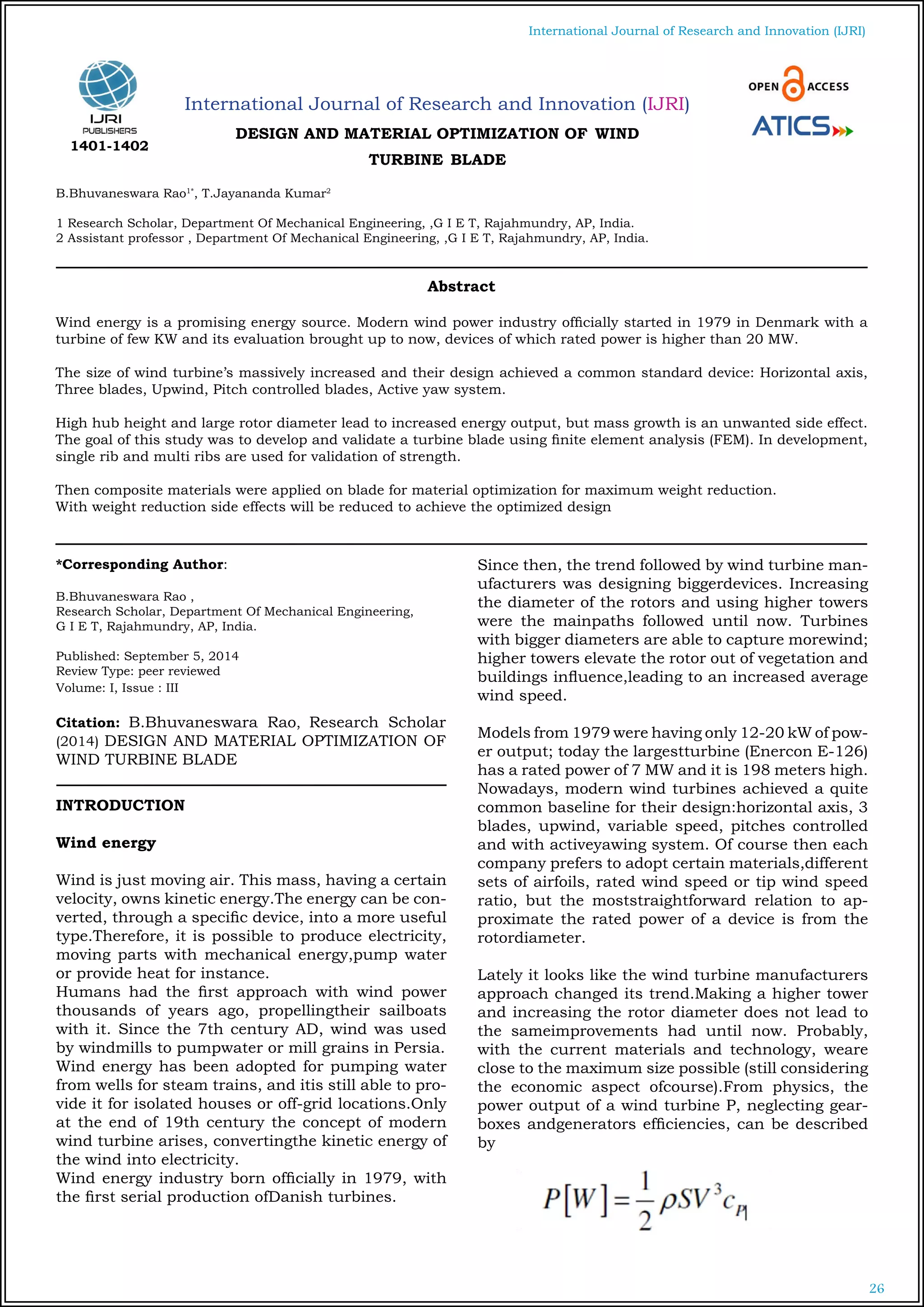
Where _ [kg/m3] is the air density, S [m2]
is the swept
area of the rotor (thusS=_D2/4), V [m/s] is the wind
speed and cP[-] is the coefficient of performance. Th-
epower output then scales with the square of the ro-
tor diameter.The mass instead scales with the cube
of the rotor diameter, in fact creating a limitabove
which increasing the size is not economically prof-
itable anymore. Due totechnology improvements,
throughout the years the real coefficients have been
2.155and 2.6, respectively.
The new designs focus on other aspects than “size”.
For instance, improving theefficiency of the blade
reduces the fatigue loads, increasing the life cycleof
thecomponents, as well as more accurate internal
blade design can reduce the amount ofmaterial uti-
lised, making the rotor lighter and cheaper.
Advanced aerodynamic technologies are also em-
braced to achieve better and cheaperresults.De-
velopment of smart rotors, winglets, flaps, gurney
flaps, micro tabs and vortexgenerators is a daily ba-
sis topic. All these technologies are meant to control
or limitthe harmful loads, leading to less fatigue and
therefore longer life cycle or lessmaterials.
Enercon E-48, blade tip winglet WhalePower blade
leading edge
Blade structural design
Actiflow Preliminary Studies
Actiflow already applied successfully active BLS tech-
nology on cars and in order toimprove wind tunnel
testing. In 2007, Actiflow started focusing on the ap-
plication ona wind turbine blade. The strong belief in
this technology and the knowledge gatheredby paral-
lel applications translated into a patent.
This patent describes how the centrifugal effect giv-
en by the rotation of the rotorcreates a pressure dif-
ference between the two sides of the panel through
which suctionoccurs. It does not give a specific final
solution or describe a particular blade speciallyde-
signed for BLS applications.
It is rather a collection of thoughts and considera-
tionson how apply this technology, evaluating and
giving as example several solutions.For instance, the
precise flap wise position on which apply the porous
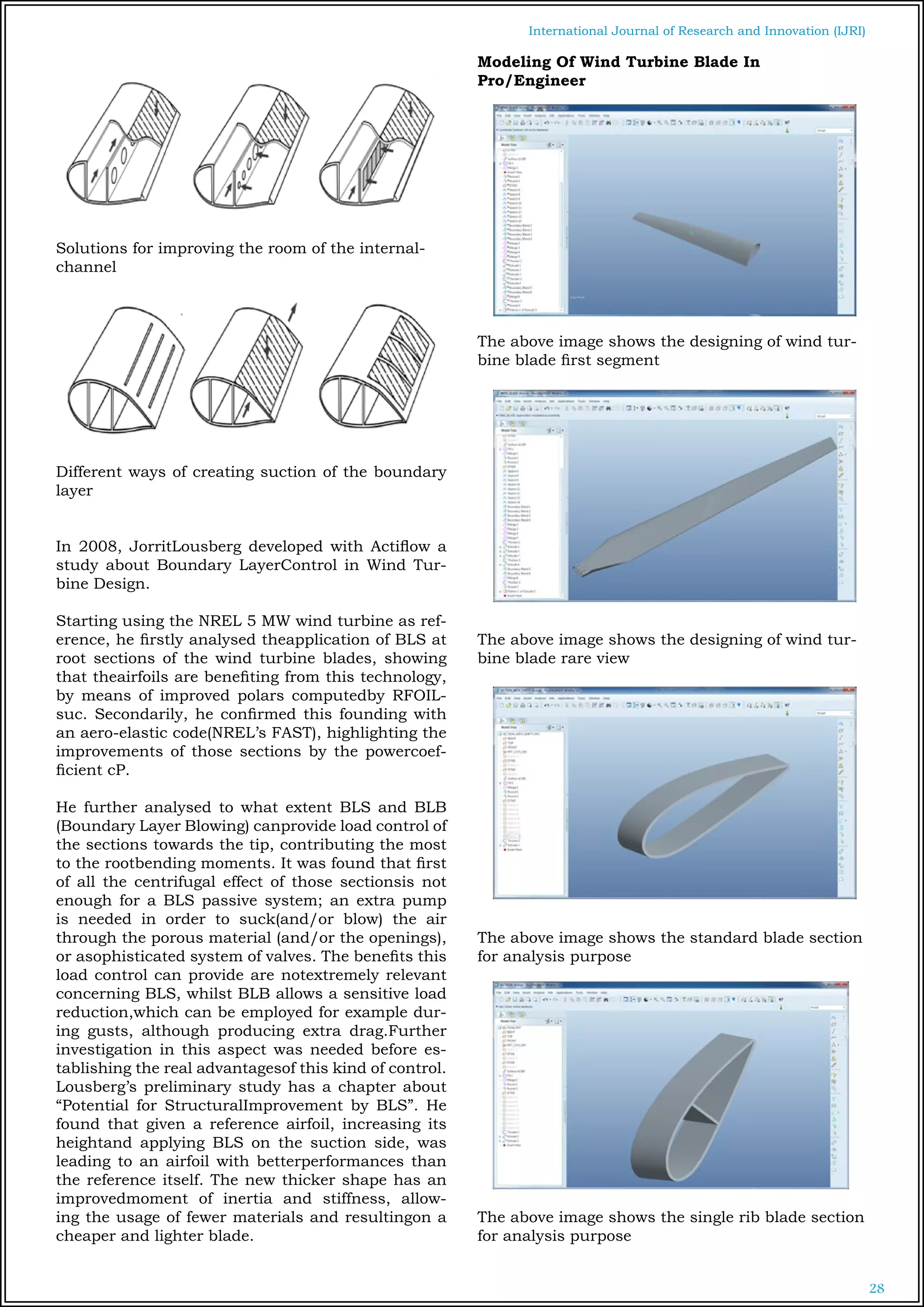
material is notDefined as well as how the room of the
internal channels is utilized
In addition, the utilization of some slots instead of
the porous material surface is takeninto account, as
well as how the latter should be applied on the blade
Since the application for the patent, internship and
graduation projects incollaboration with Delft Uni-
versity of Technology have been developed, refin-
ing thechoices of the real possible applications and
brightening the achievable improvements.
3. 28
International Journal of Research and Innovation (IJRI)
Solutions for improving the room of the internal-
channel
Different ways of creating suction of the boundary
layer
In 2008, JorritLousberg developed with Actiflow a
study about Boundary LayerControl in Wind Tur-
bine Design.
Starting using the NREL 5 MW wind turbine as ref-
erence, he firstly analysed theapplication of BLS at
root sections of the wind turbine blades, showing
that theairfoils are benefiting from this technology,
by means of improved polars computedby RFOIL-
suc. Secondarily, he confirmed this founding with
an aero-elastic code(NREL’s FAST), highlighting the
improvements of those sections by the powercoef-
ficient cP.
He further analysed to what extent BLS and BLB
(Boundary Layer Blowing) canprovide load control of
the sections towards the tip, contributing the most
to the rootbending moments. It was found that first
of all the centrifugal effect of those sectionsis not
enough for a BLS passive system; an extra pump
is needed in order to suck(and/or blow) the air
through the porous material (and/or the openings),
or asophisticated system of valves. The benefits this
load control can provide are notextremely relevant
concerning BLS, whilst BLB allows a sensitive load
reduction,which can be employed for example dur-
ing gusts, although producing extra drag.Further
investigation in this aspect was needed before es-
tablishing the real advantagesof this kind of control.
Lousberg’s preliminary study has a chapter about
“Potential for StructuralImprovement by BLS”. He
found that given a reference airfoil, increasing its
heightand applying BLS on the suction side, was
leading to an airfoil with betterperformances than
the reference itself. The new thicker shape has an
improvedmoment of inertia and stiffness, allow-
ing the usage of fewer materials and resultingon a
cheaper and lighter blade.
Modeling Of Wind Turbine Blade In
Pro/Engineer
The above image shows the designing of wind tur-
bine blade first segment
The above image shows the designing of wind tur-
bine blade rare view
The above image shows the standard blade section
for analysis purpose
The above image shows the single rib blade section
for analysis purpose
4. 29
International Journal of Research and Innovation (IJRI)
Introduction To Ansys
ANSYS is general-purpose finite element analysis
(FEA) software package. Finite Element Analysis
is a numerical method of deconstructing a complex
system into very small pieces (of user-designated
size) called elements. The software implements
equations that govern the behaviour of these ele-
ments and solves them all; creating a comprehen-
sive explanation of how the system acts as a whole.
These results then can be presented in tabulated,
or graphical forms. This type of analysis is typically
used for the design and optimization of a system far
too complex to analyze by hand. Systems that may
fit into this category are too complex due to their
geometry, scale, or governing equations.
ANSYS provides a cost-effective way to explore the
performance of products or processes in a virtual
environment. This type of product development is
termed virtual prototyping.
Structural Analysis of wind turbine
blade
The above image is showing imported model from
pro-e to the format of (IGES) Initial Graphics Ex-
change Specification
The above image shows thedisplacement
The above image shows the Von-misses stress
Analysis of wind turbine blade wing using E-
glass with single rib
The above image shows the displacement
5. 30
International Journal of Research and Innovation (IJRI)
The above image shows the Von-misses stress
Structural Analysis of wind turbine blade wing
using E-glass with dual rib
The above image shows the displacement
The above image shows the Von-misses stress
E-Glass
Hallow
section
Single rib Dual rib
Displacement 0.027 0.027 0.027
Stress 13.286 12.829 13.069
Mode1 1.806 1.799 1.815
Mode2 1.872 1.867 1.874
Mode3 1.549 1.539 1.553
Mode4 1.777 1.775 1.801
Mode5 1.412 1.422 1.409
S2-Glass
Hallow
section
Single rib Dual rib
Displacement 0.022 0.022 0.022
Stress 12.842 12.736 12.995
Mode1 1.862 1.847 1.864
Mode2 1.919 1.917 1.923
Mode3 1.587 1.580 1.595
Mode4 1.826 1.821 1.848
Mode5 1.460 1.462 1.008
DISCUSSIONS
• The project work is done to suggest optimum blade
design and suitable material to minimize the weight
to get maximum output from the wind turbine.
• Weight is one of the major criteria which effect in
power generation using wind power.
• In this project different types of cross sections are
analyzed with change of rib sections and also two
composite materials are used to analyze the blade
sections.
• These E glass (FRP) & S2-glass (ERP) materials are
having low density value than traditional materials.
• As per the analytical results single rib is showing
good structural and frequency characteristics.
• So better to use single rib section for wind turbine
blade.
• While comparing the materials S2 glass is showing
better structural stability than E glass.
CONCLUSION
This project work deals with turbine blade inner
section design modification and material replace-
ment of the traditional material for the maximum
weight reduction to obtain maximum output from
the turbine.
Initially literature survey is done on wind turbine
blade to design and optimization for further safety.
Full blade and blade section modeling is done us-
ing pro-engineering , blade sections are generated
in surface module also for the purpose of analysis
using material matrix (layers) method.
Static and modal analysis is done on standard sin-
gle rib and two rib sections using shell element with
“5” layer with 90O, 45O, 0O, - 45O, 90O orientation
in material matrix.
As per the analytical results single rib section is
better than standard and two rib sections, S2-glass
epoxy and E-glass epoxy both materials are having
nearest values.( S2 is having little bit high strength
than E-glass).
According to the above results and discussion this
project work concludes that single rib section wind
turbine blade along with E-glass epoxy is the better
option , because of good structural stability , low
frequency, and low cost than S2-glass.
6. 31
International Journal of Research and Innovation (IJRI)
REFERENCES
1) Model Validation And Structural Analysis Of A
Small Wind Turbine blade
2) Structural design and analysis of a 10 MW wind
turbine blade Kevin Cox, PhD Candidate, Dept. of
Engineering Design and Materials NTNU
3) Structural Design of a 5 MW Wind Turbine Blade
Equipped with Boundary Layer Suction Technolog-
yAnalysis and lay-up optimization applying a prom-
ising technologyFederico Ghedin
4) Hermann Glauert FRS, FRAeS J. A. D. Ack-
roydFormer Aerospace Division Manchester School
of EngineeringVictoria University of Manchester, UK
Author
B.Bhuvaneswara Rao1*
,
Research Scholar, Department Of Mechanical
Engineering, G I E T, Rajahmundry, AP, India.
T.Jayananda Kumar2
Assistant professor , Department Of Mechanical
Engineering, ,G I E T, Rajahmundry, AP, India.