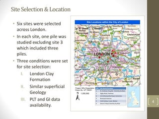
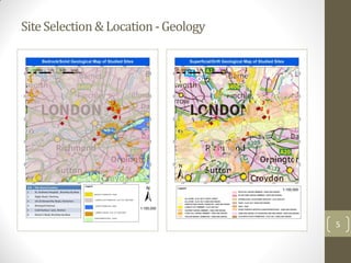
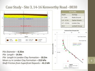
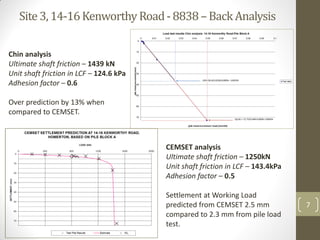
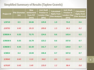
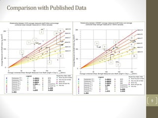
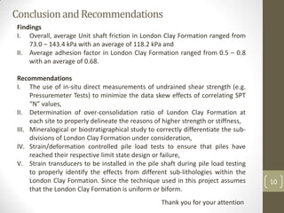
The analysis of unit shaft (skin) friction
and adhesion factor (α) for piles
constructed in London Clay Formation
using the Continuous Flight Auger (CFA)
technique
By: Abdul Aziz Zantout
Background,Aims&Objectives
Background
• Deep foundations in the form of continuous flight auger (CFA) piles
are the choice of piling technique in urban areas with unlithified
deposits due to associated low vibrations and noise levels during
construction (Tomlinson & Woodward, 2008).
Aims
• Analyse the unit shaft friction and adhesion factor (α) for CFA pile
constructed in London Clay Formation (LCF).
Objectives
• Extract data from Ground Investigation
• Calculate Ultimate Shaft Friction (USF) from superficial deposits
• Calculate mean undrained shear strength in LCF
• Back analyse pile load test data
2
DissertationFlowChart
I. Desk Study
Background Study
Site Selection based
on
I. Geology and
II. data availability
II. Analysis
(repeated for
each site)
Ultimate Shaft
Friction (USF) from
superficial deposits
Mean undrained
shear strength in LCF
Back analysis of load
tests to obtain USF
(Chin and CEMSET)
Obtain unit shaft
friction and α in LCF
III. Evaluation
Comparison with
published data
Result presentation &
conclusion
Recommendations
for further study
3
SiteSelection&Location
4
• Six sites were selected
across London.
• In each site, one pile was
studied excluding site 3
which included three
piles.
• Three conditions were set
for site selection:
I. London Clay
Formation
II. Similar superficial
Geology
III. PLT and GI data
availability.
SiteSelection&Location-Geology
5
CaseStudy-Site3,14-16KenworthyRoad-8838
6
Soil Profile
Depth Geology
0 – 1.4m Made Ground
1.4 – 4.7m Taplow Gravels
4.7 – 22.4m London Clay
22.4 Lambeth Group
Pile Diameter – 0.35m
Pile Length – 14.9m
Pile Length in London Clay Formation – 10.2m
Mean cu in London Clay Formation – 213 kPa
Shaft Friction from Superficial Deposits – 41.3 kN
Made
Ground
Taplow
Gravels
London Clay
Formation
Lambeth
Group
Legend
Site3,14-16KenworthyRoad-8838–BackAnalysis
7
Chin analysis
Ultimate shaft friction – 1439 kN
Unit shaft friction in LCF – 124.6 kPa
Adhesion factor – 0.6
Over prediction by 13% when
compared to CEMSET.
CEMSET analysis
Ultimate shaft friction – 1250kN
Unit shaft friction in LCF – 143.4kPa
Adhesion factor – 0.5
Settlement at Working Load
predicted from CEMSET 2.5 mm
compared to 2.3 mm from pile load
test.
SimplifiedSummaryofResults(TaplowGravels)
8
Project ID
Pile Diameter
(m)
Max
Settlement
from PLT
(mm)
Unit Shaft
Friction in
London Clay
(kPa)
Calculated
Alpha from
Chin Analysis
Unit Shaft
Friction in
London Clay
(kPa)
Calculated
Alpha from
Chin Analysis
1/8710 0.5 34.84 129.8 1.0 73.0 0.6
2/8793 0.45 19.15 209.8 1.5 34.3 0.2
3/8838 A 0.35 72.75 124.6 0.6 143.4 0.5
3/8838 B 0.35 16.79 123.2 0.6 107.8 0.7
3/8838 C 0.35 63.39 141.7 0.7 139.0 0.7
4/8854 0.4 10.04 106.8 0.7 107.8 0.7
5/9043 0.45 5.13 54.0 0.5 111.1 1.4
6/9169 0.45 5.49 135.0 1.2 98.4 0.8
ComparisonwithPublishedData
9
2
6
1
5
4
3B
3A
3C
2
1
5
6
4
3A
3B
3C
ConclusionandRecommendations
10
Findings
I. Overall, average Unit shaft friction in London Clay Formation ranged from
73.0 – 143.4 kPa with an average of 118.2 kPa and
II. Average adhesion factor in London Clay Formation ranged from 0.5 – 0.8
with an average of 0.68.
Recommendations
I. The use of in-situ direct measurements of undrained shear strength (e.g.
Pressuremeter Tests) to minimize the data skew effects of correlating SPT
“N” values,
II. Determination of over-consolidation ratio of London Clay Formation at
each site to properly delineate the reasons of higher strength or stiffness,
III. Mineralogical or biostratigraphical study to correctly differentiate the sub-
divisions of London Clay Formation under consideration,
IV. Strain/deformation controlled pile load tests to ensure that piles have
reached their respective limit state design or failure,
V. Strain transducers to be installed in the pile shaft during pile load testing
to properly identify the effects from different sub-lithologies within the
London Clay Formation. Since the technique used in this project assumes
that the London Clay Formation is uniform or biform.
Thank you for your attention

Presentation_Abdul Aziz Zantout_UP706051

  • 1.
    The analysis ofunit shaft (skin) friction and adhesion factor (α) for piles constructed in London Clay Formation using the Continuous Flight Auger (CFA) technique By: Abdul Aziz Zantout
  • 2.
    Background,Aims&Objectives Background • Deep foundationsin the form of continuous flight auger (CFA) piles are the choice of piling technique in urban areas with unlithified deposits due to associated low vibrations and noise levels during construction (Tomlinson & Woodward, 2008). Aims • Analyse the unit shaft friction and adhesion factor (α) for CFA pile constructed in London Clay Formation (LCF). Objectives • Extract data from Ground Investigation • Calculate Ultimate Shaft Friction (USF) from superficial deposits • Calculate mean undrained shear strength in LCF • Back analyse pile load test data 2
  • 3.
    DissertationFlowChart I. Desk Study BackgroundStudy Site Selection based on I. Geology and II. data availability II. Analysis (repeated for each site) Ultimate Shaft Friction (USF) from superficial deposits Mean undrained shear strength in LCF Back analysis of load tests to obtain USF (Chin and CEMSET) Obtain unit shaft friction and α in LCF III. Evaluation Comparison with published data Result presentation & conclusion Recommendations for further study 3
  • 4.
    SiteSelection&Location 4 • Six siteswere selected across London. • In each site, one pile was studied excluding site 3 which included three piles. • Three conditions were set for site selection: I. London Clay Formation II. Similar superficial Geology III. PLT and GI data availability.
  • 5.
  • 6.
    CaseStudy-Site3,14-16KenworthyRoad-8838 6 Soil Profile Depth Geology 0– 1.4m Made Ground 1.4 – 4.7m Taplow Gravels 4.7 – 22.4m London Clay 22.4 Lambeth Group Pile Diameter – 0.35m Pile Length – 14.9m Pile Length in London Clay Formation – 10.2m Mean cu in London Clay Formation – 213 kPa Shaft Friction from Superficial Deposits – 41.3 kN Made Ground Taplow Gravels London Clay Formation Lambeth Group Legend
  • 7.
    Site3,14-16KenworthyRoad-8838–BackAnalysis 7 Chin analysis Ultimate shaftfriction – 1439 kN Unit shaft friction in LCF – 124.6 kPa Adhesion factor – 0.6 Over prediction by 13% when compared to CEMSET. CEMSET analysis Ultimate shaft friction – 1250kN Unit shaft friction in LCF – 143.4kPa Adhesion factor – 0.5 Settlement at Working Load predicted from CEMSET 2.5 mm compared to 2.3 mm from pile load test.
  • 8.
    SimplifiedSummaryofResults(TaplowGravels) 8 Project ID Pile Diameter (m) Max Settlement fromPLT (mm) Unit Shaft Friction in London Clay (kPa) Calculated Alpha from Chin Analysis Unit Shaft Friction in London Clay (kPa) Calculated Alpha from Chin Analysis 1/8710 0.5 34.84 129.8 1.0 73.0 0.6 2/8793 0.45 19.15 209.8 1.5 34.3 0.2 3/8838 A 0.35 72.75 124.6 0.6 143.4 0.5 3/8838 B 0.35 16.79 123.2 0.6 107.8 0.7 3/8838 C 0.35 63.39 141.7 0.7 139.0 0.7 4/8854 0.4 10.04 106.8 0.7 107.8 0.7 5/9043 0.45 5.13 54.0 0.5 111.1 1.4 6/9169 0.45 5.49 135.0 1.2 98.4 0.8
  • 9.
  • 10.
    ConclusionandRecommendations 10 Findings I. Overall, averageUnit shaft friction in London Clay Formation ranged from 73.0 – 143.4 kPa with an average of 118.2 kPa and II. Average adhesion factor in London Clay Formation ranged from 0.5 – 0.8 with an average of 0.68. Recommendations I. The use of in-situ direct measurements of undrained shear strength (e.g. Pressuremeter Tests) to minimize the data skew effects of correlating SPT “N” values, II. Determination of over-consolidation ratio of London Clay Formation at each site to properly delineate the reasons of higher strength or stiffness, III. Mineralogical or biostratigraphical study to correctly differentiate the sub- divisions of London Clay Formation under consideration, IV. Strain/deformation controlled pile load tests to ensure that piles have reached their respective limit state design or failure, V. Strain transducers to be installed in the pile shaft during pile load testing to properly identify the effects from different sub-lithologies within the London Clay Formation. Since the technique used in this project assumes that the London Clay Formation is uniform or biform. Thank you for your attention