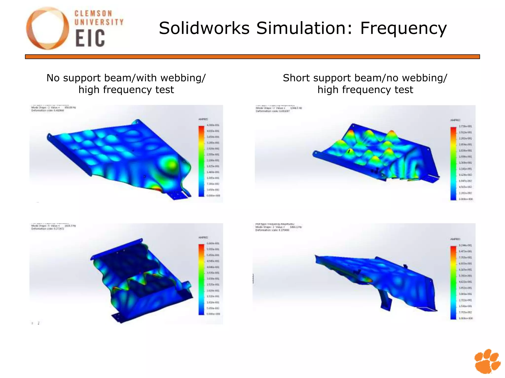
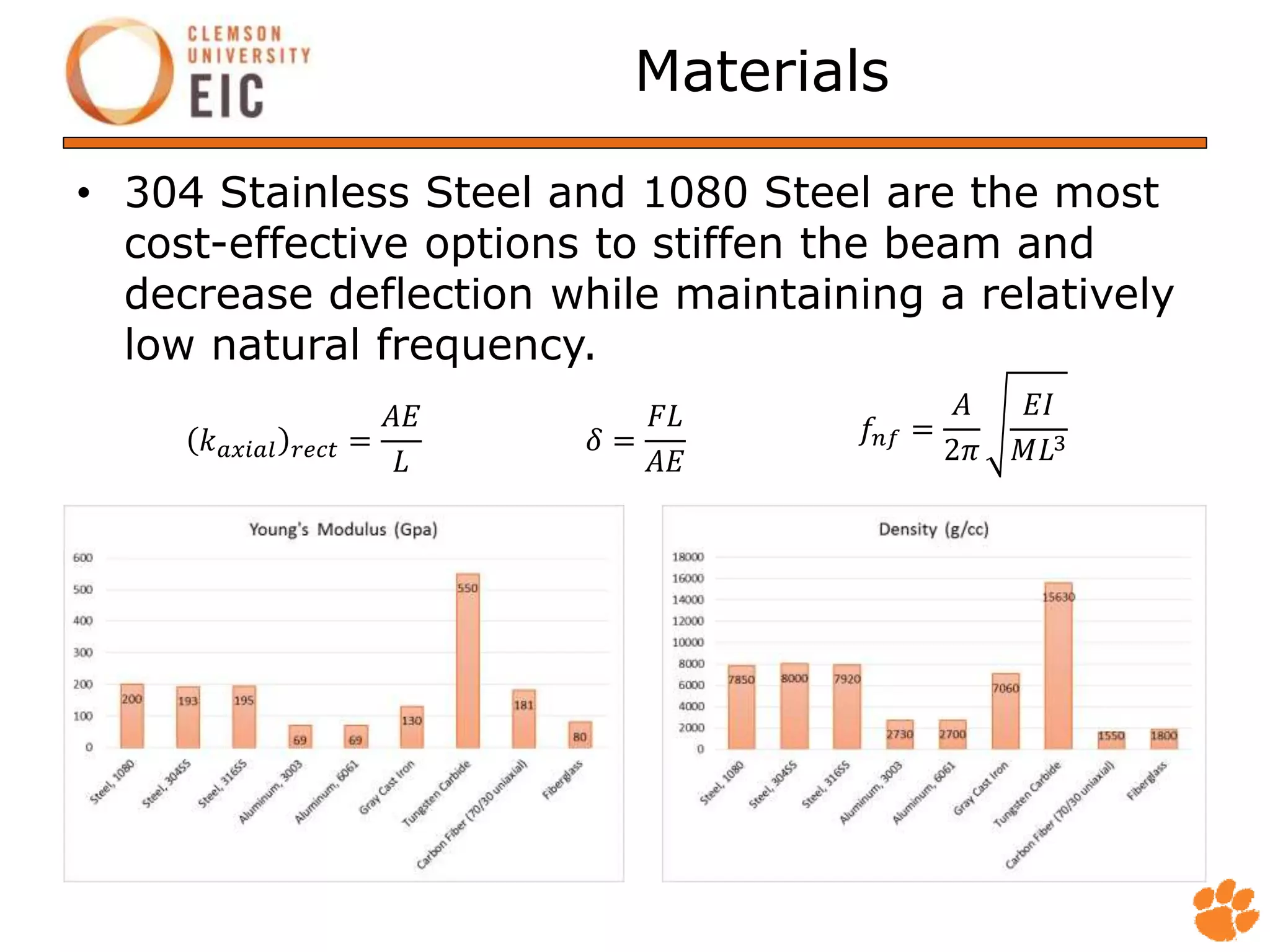
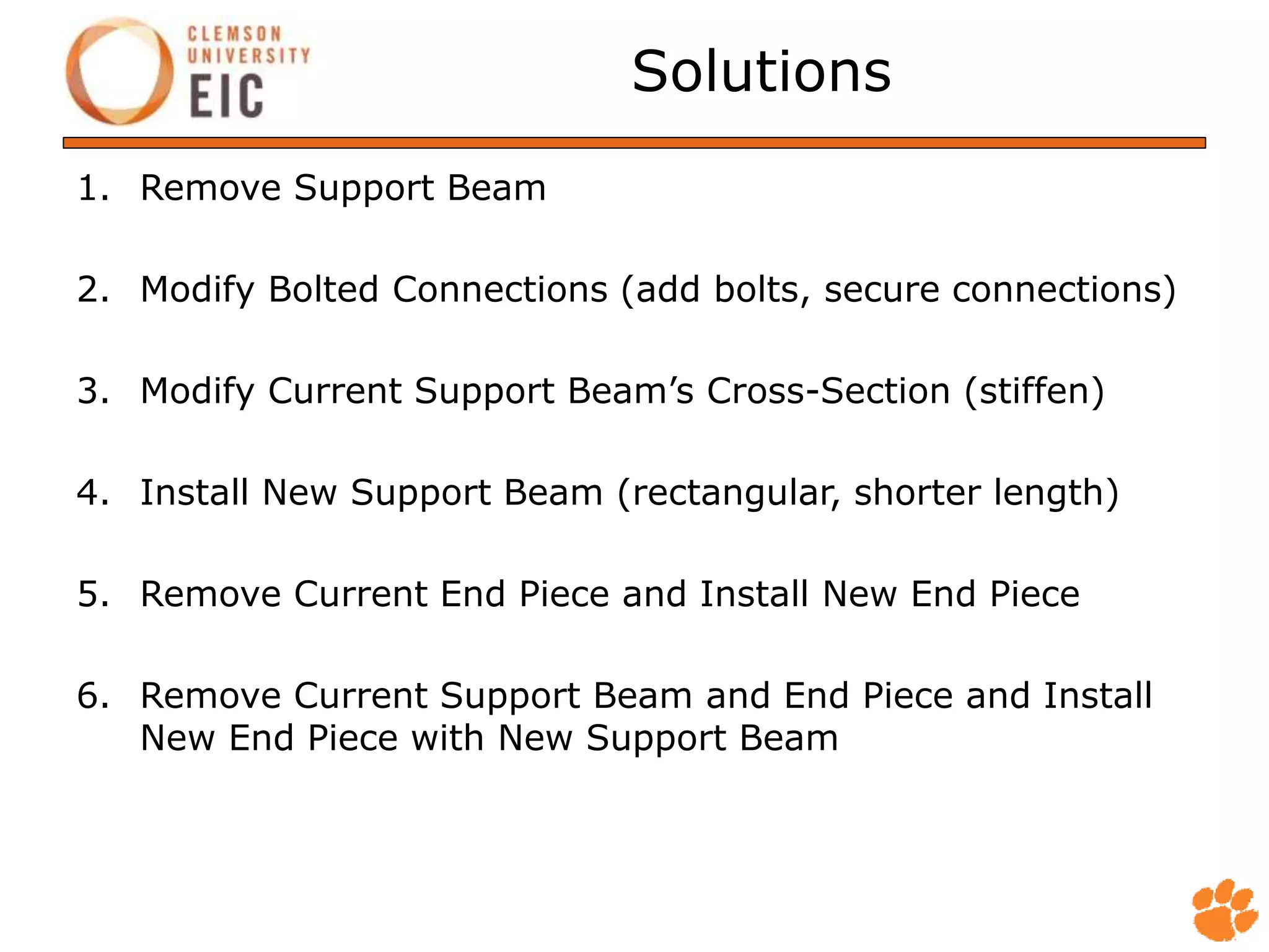
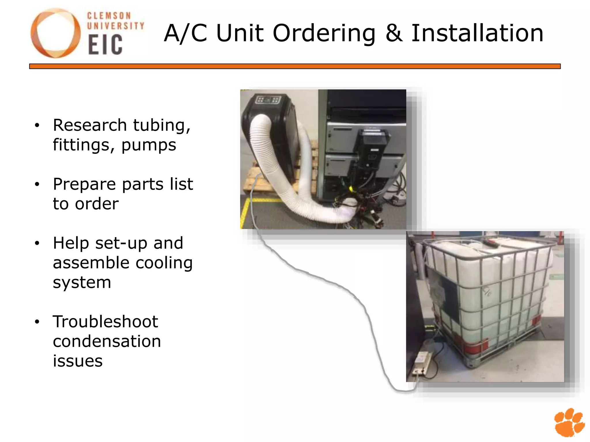
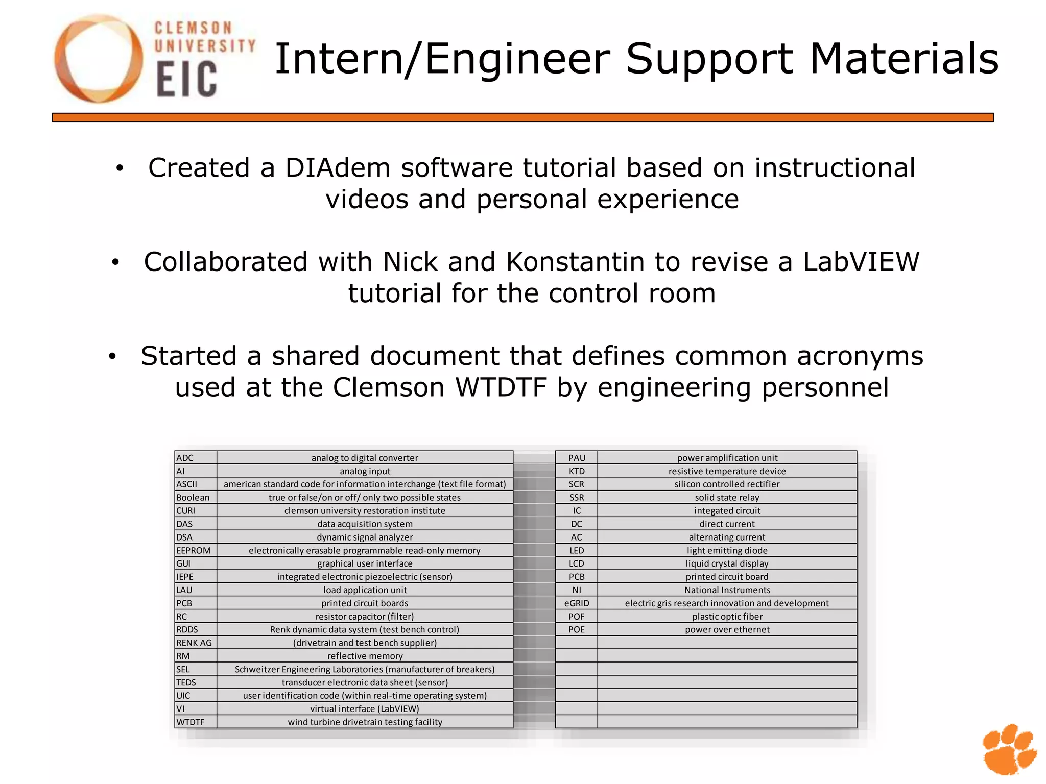
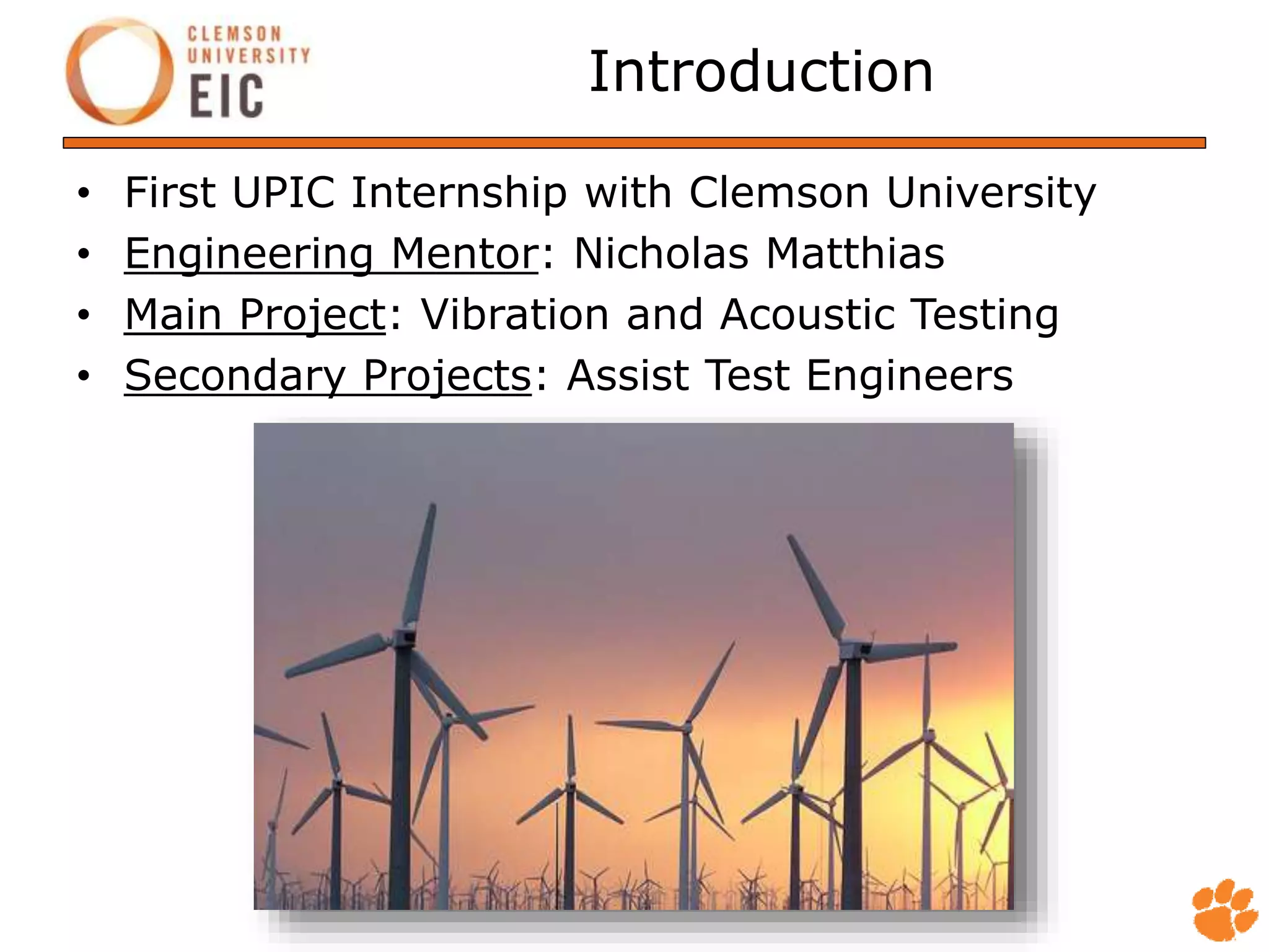
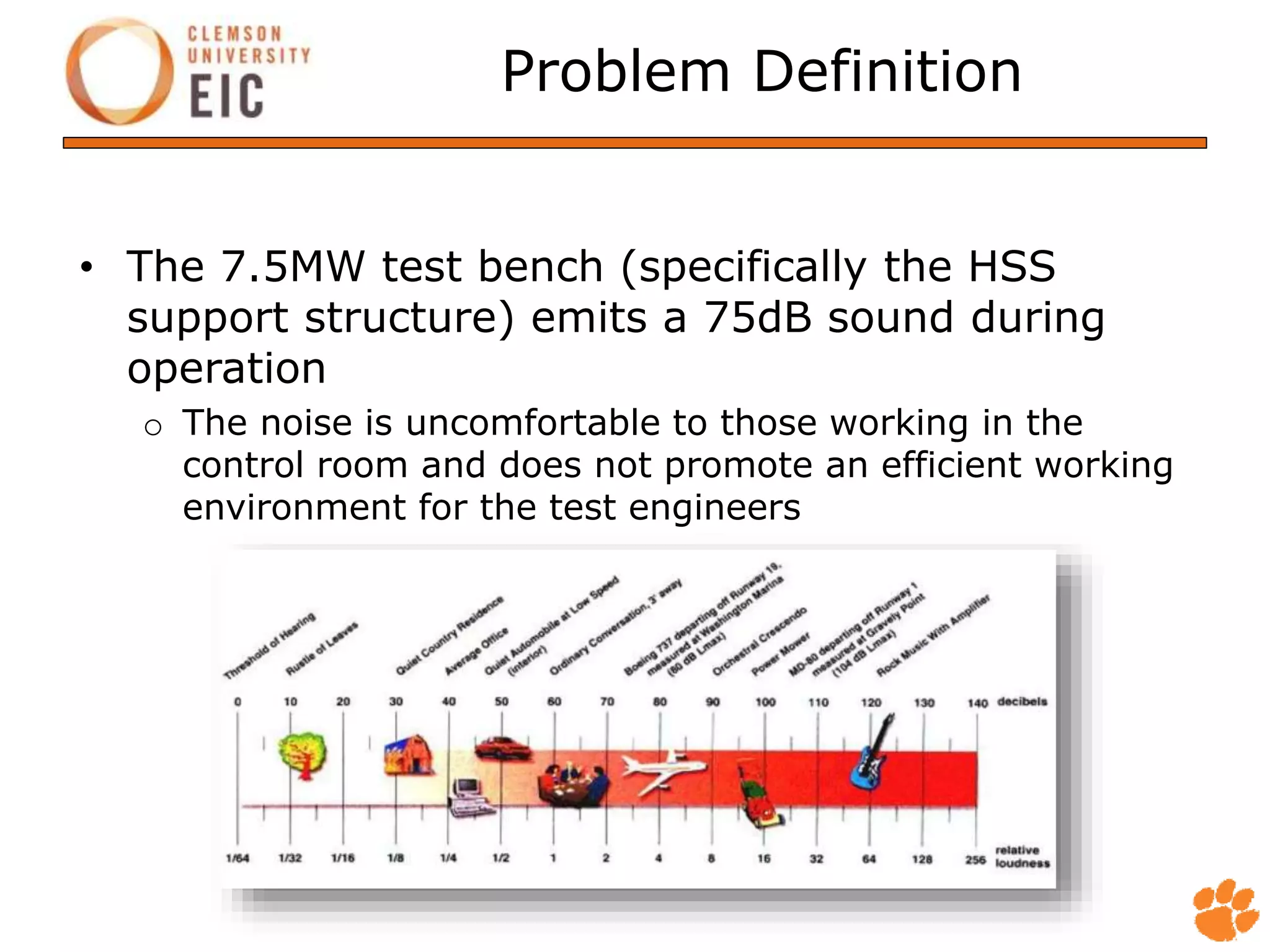
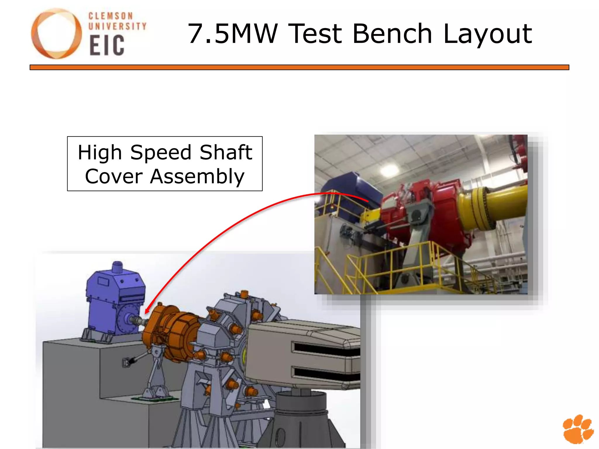
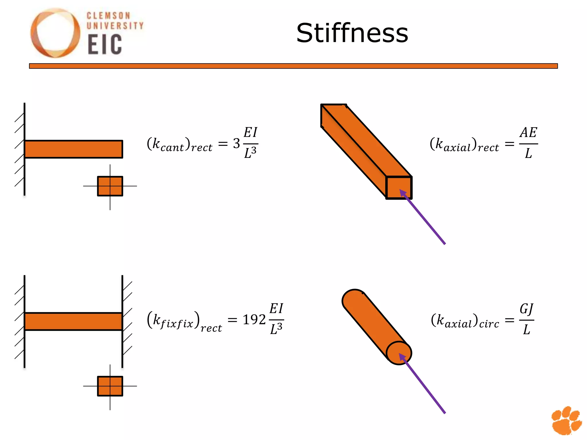
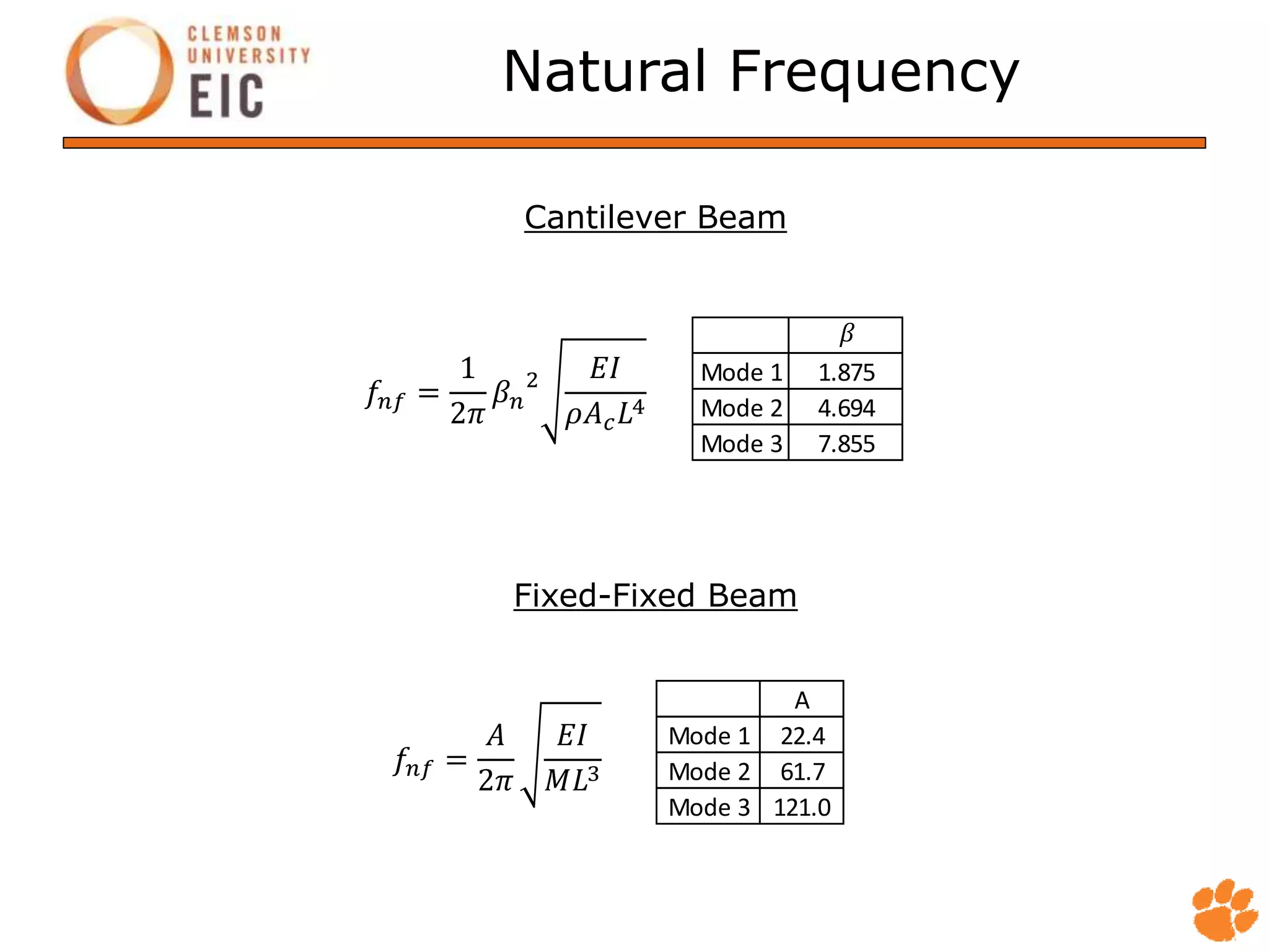
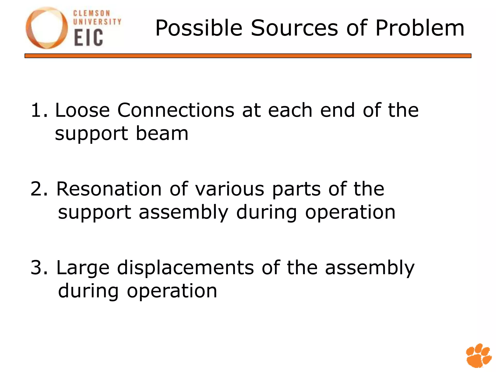
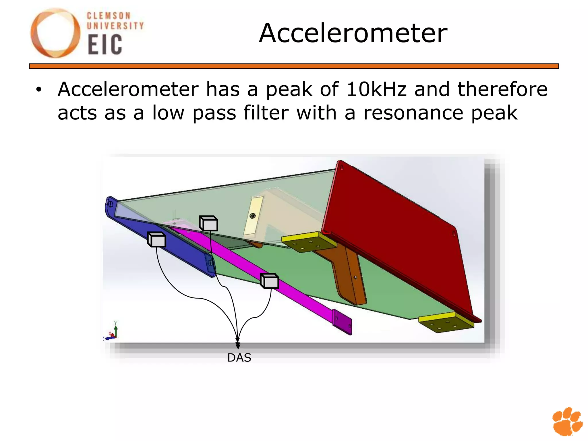
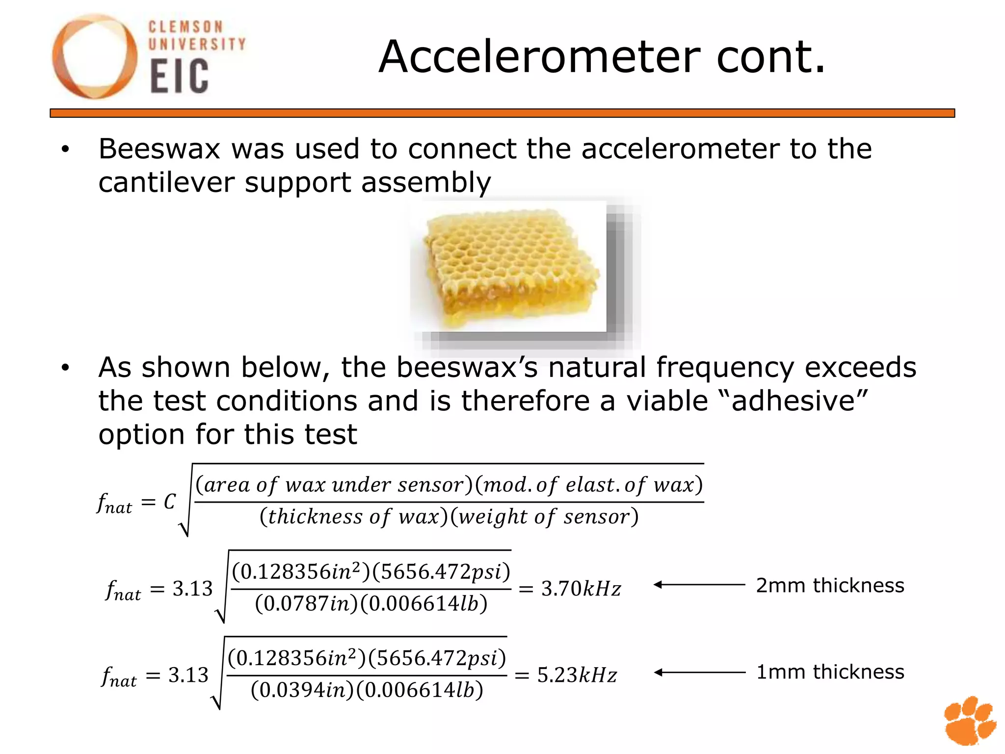
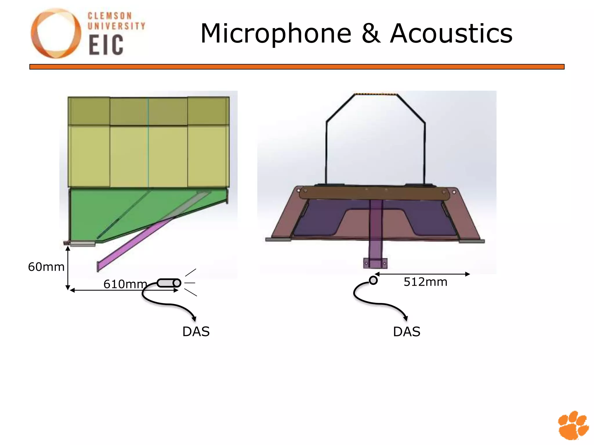
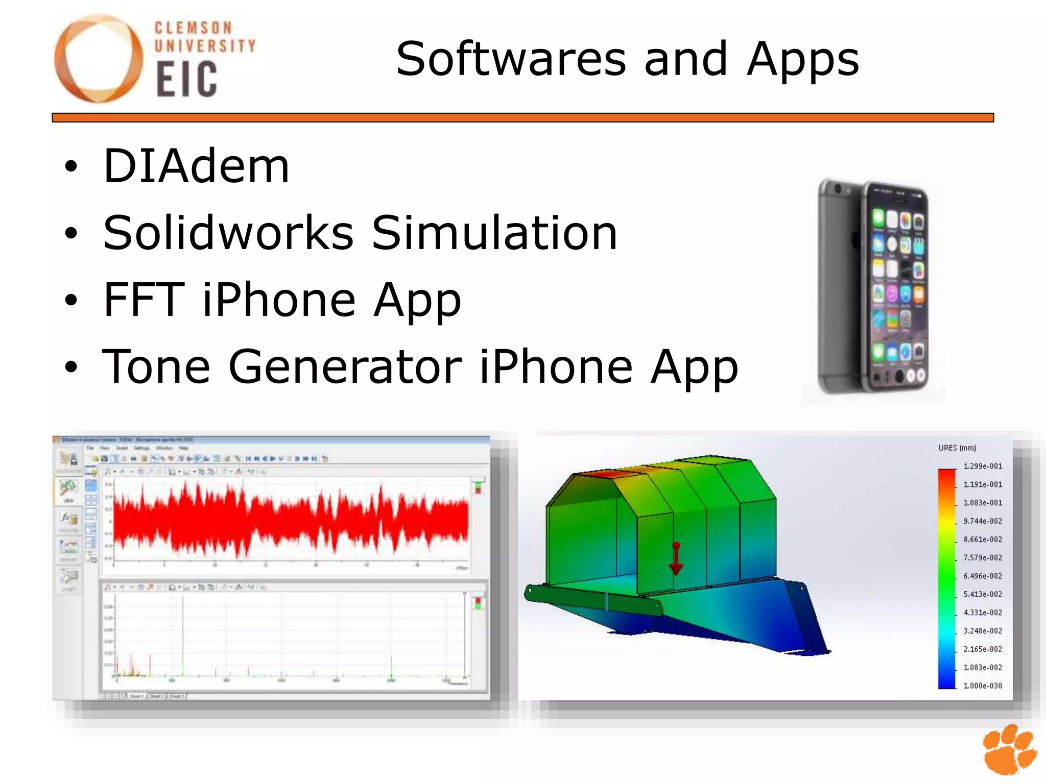
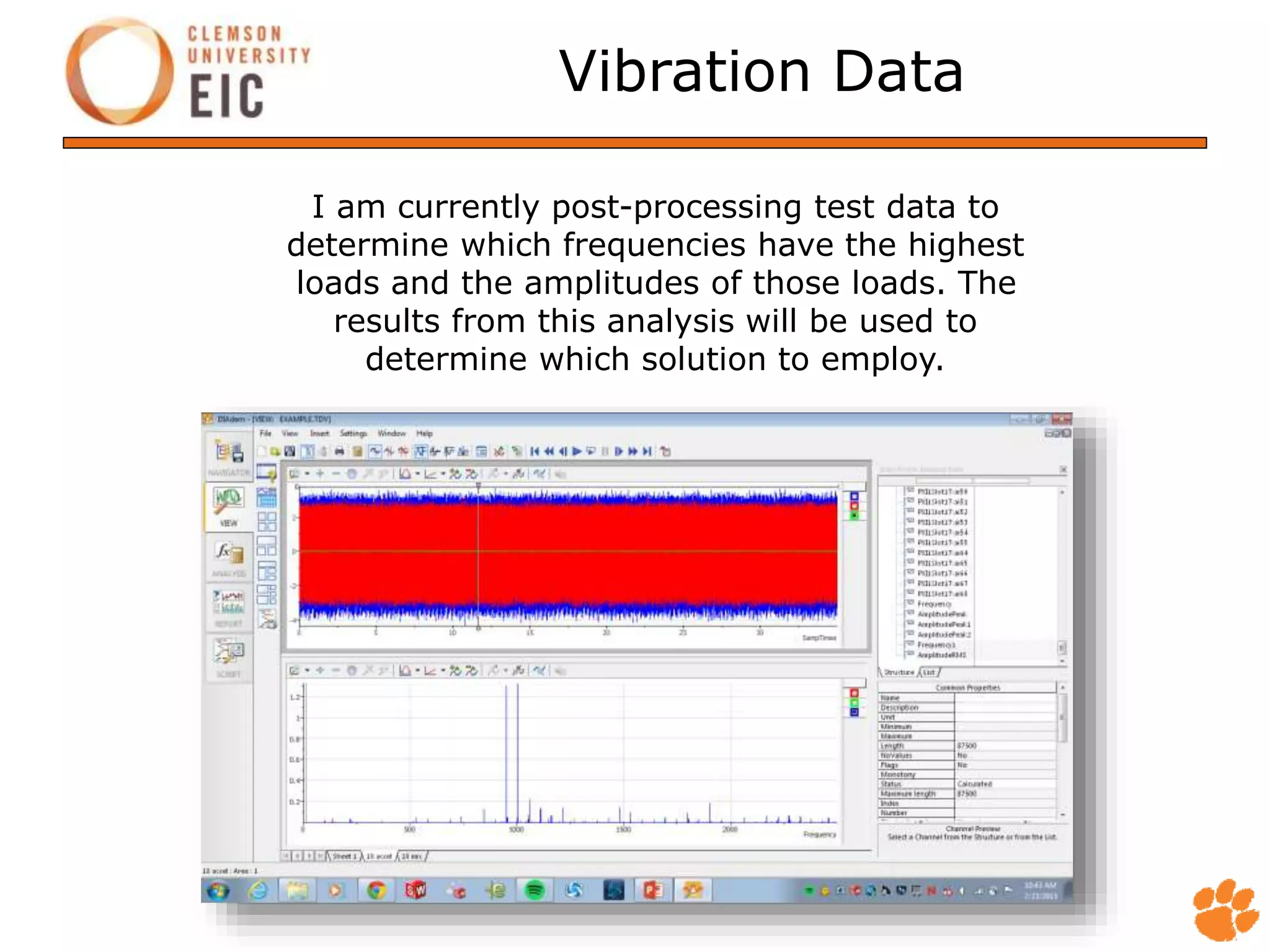
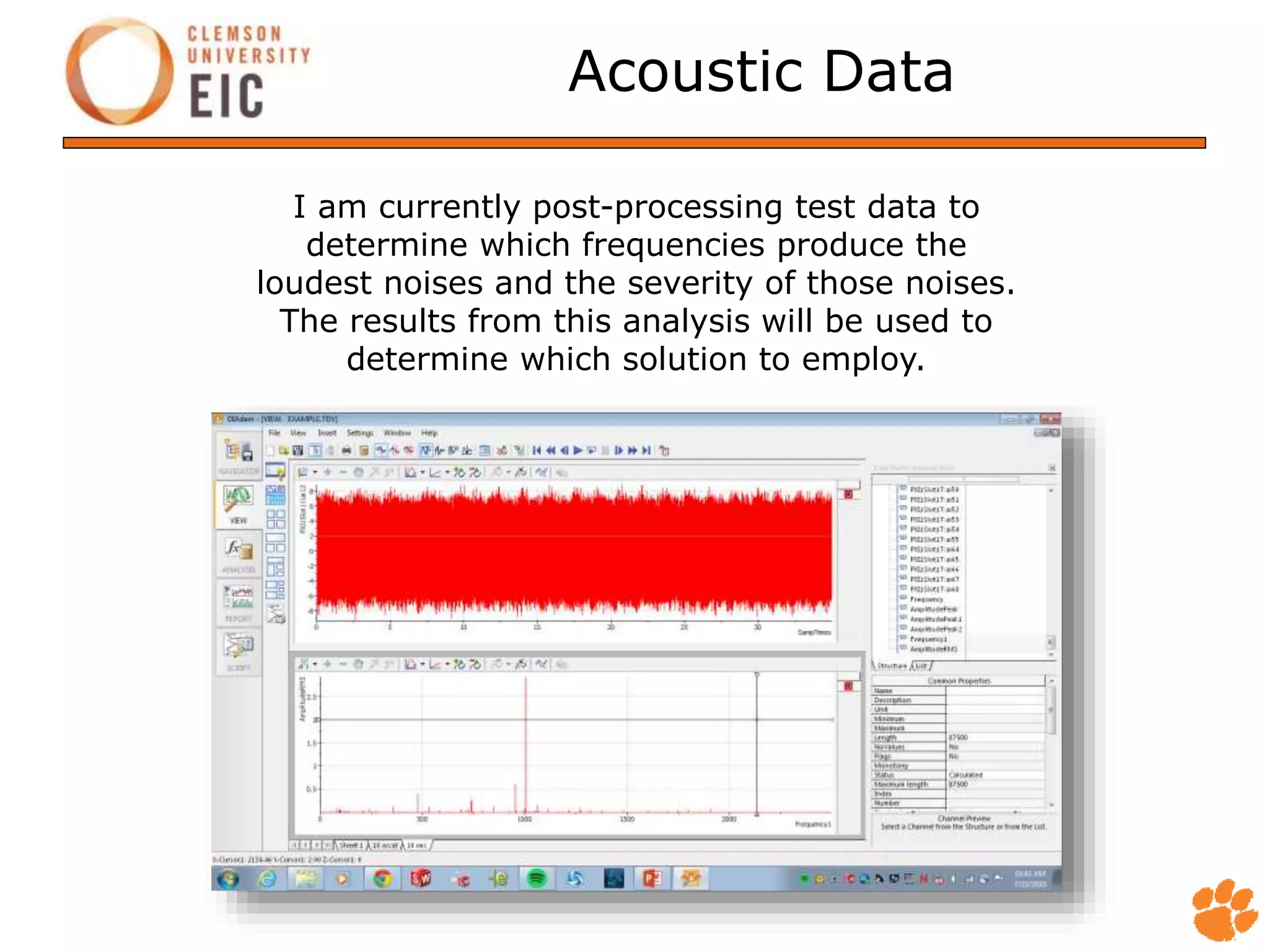
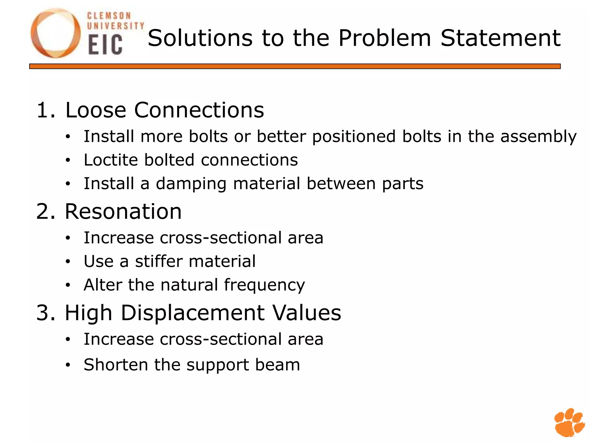
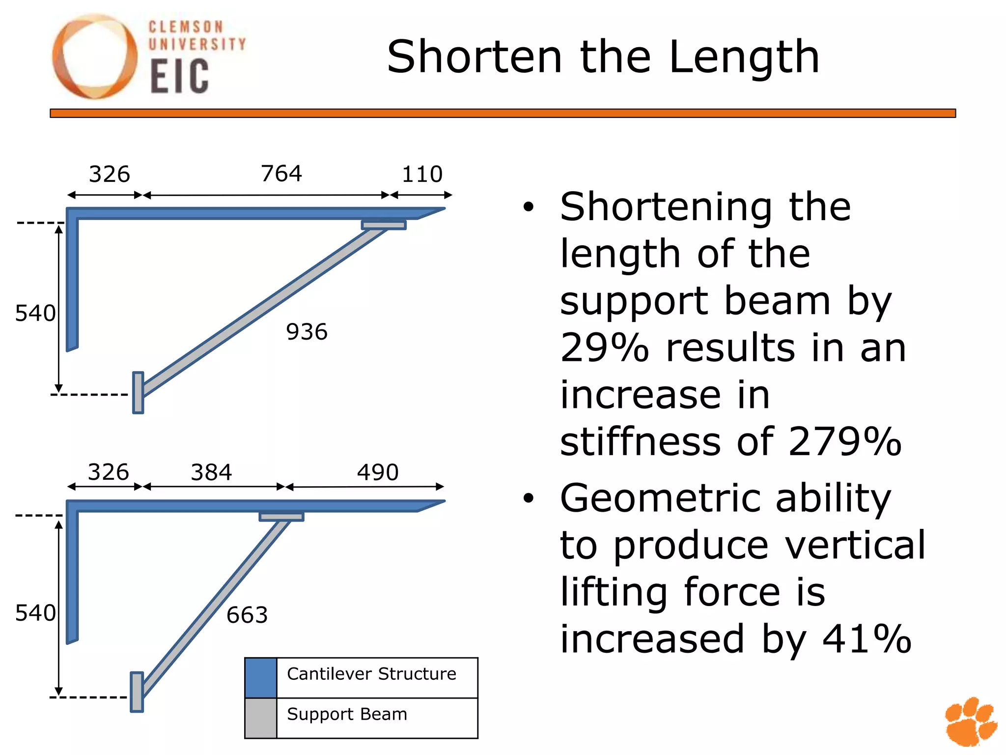
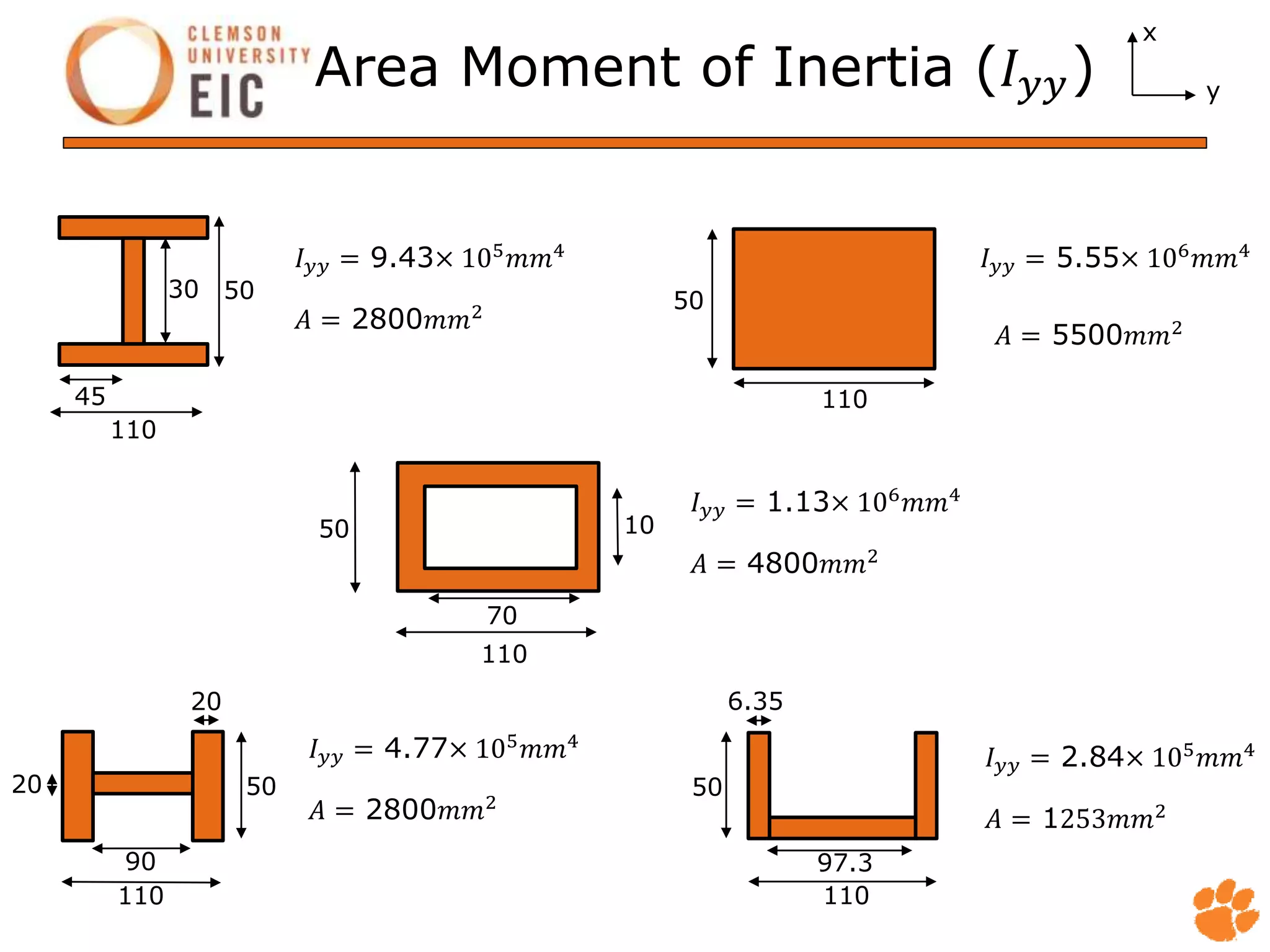
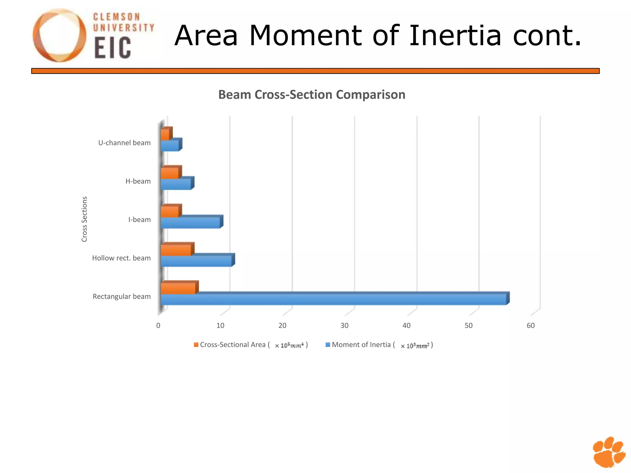
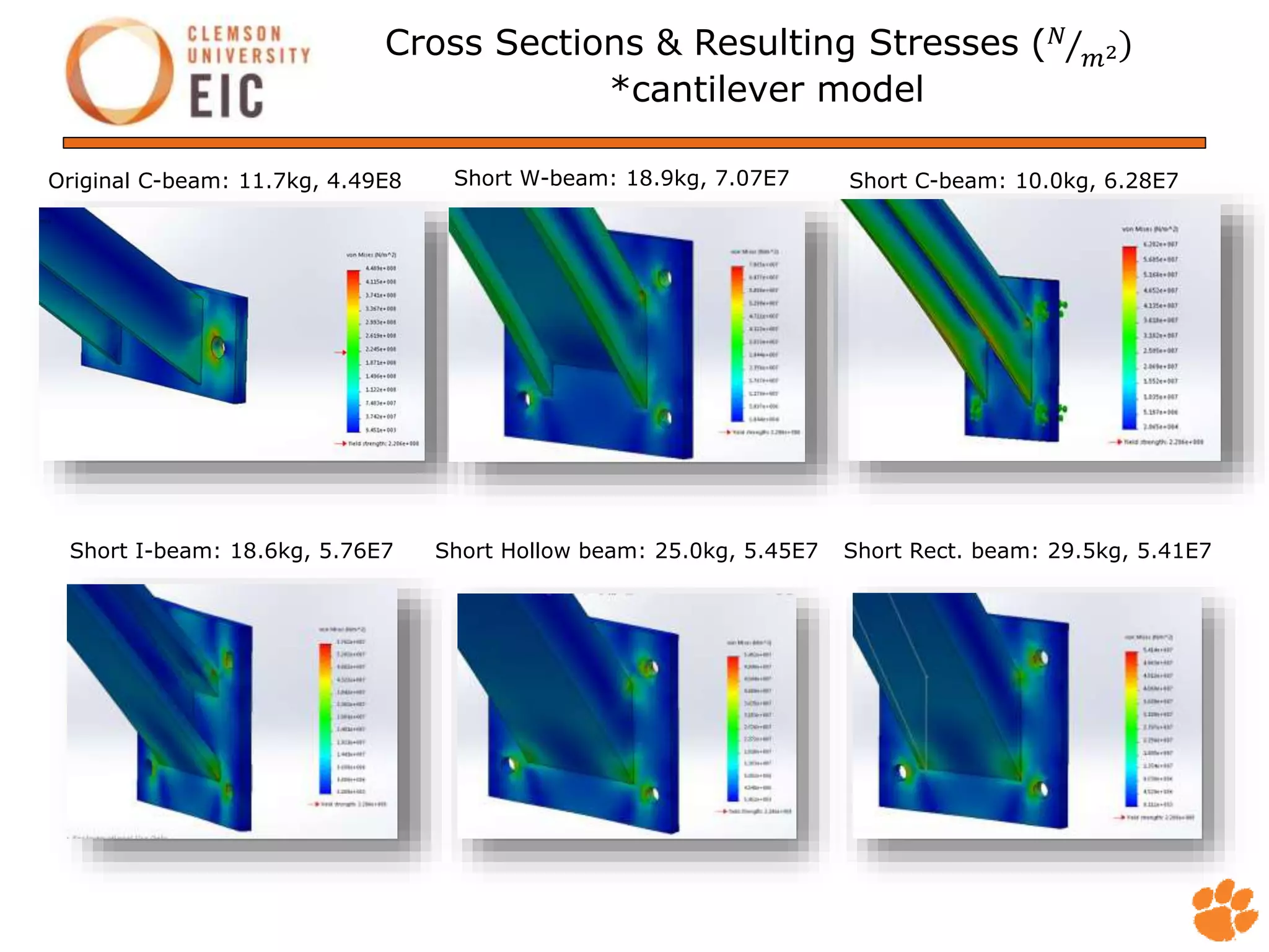
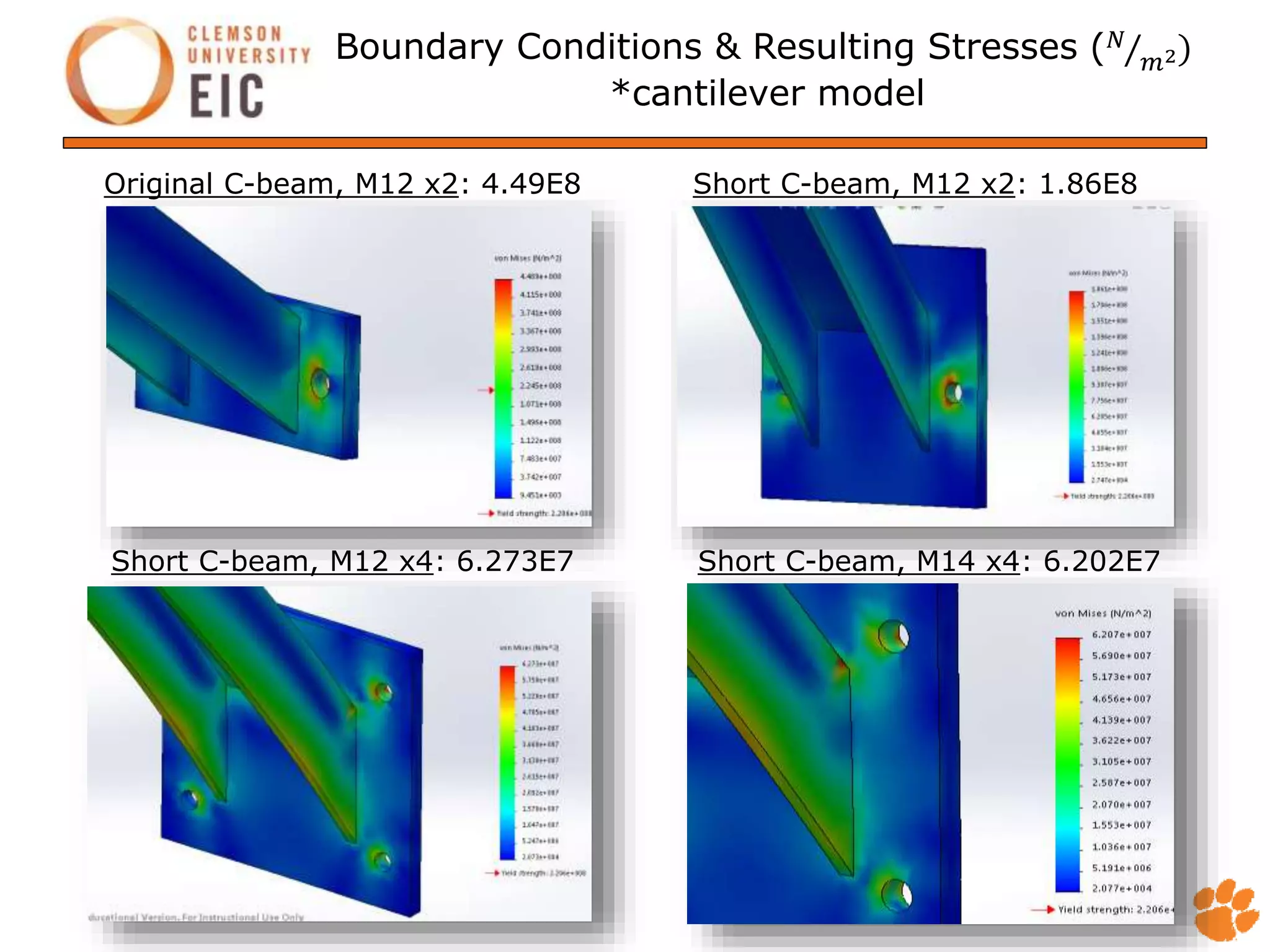
2015 Summer Internship
Final Presentation
Ash Abel
Clemson Mechanical Engineering
Exp. Graduation: May 2016
CURI WTDTF
Introduction
• First UPIC Internship with Clemson University
• Engineering Mentor: Nicholas Matthias
• Main Project: Vibration and Acoustic Testing
• Secondary Projects: Assist Test Engineers
Methodology
1. Define the Problem
2. Research Physics and Background Information
3. Hypothesize Possible Sources of the Problem
4. Design Test(s) to Confirm/Dismiss Hypotheses
5. Analyze the Test Data
6. Determine How to Eliminate the Problem
7. Design and Test Possible Solutions
8. Analyze Data and Implement Effective Solution(s)
DEFINE THE PROBLEM
Problem Definition
• The 7.5MW test bench (specifically the HSS
support structure) emits a 75dB sound during
operation
o The noise is uncomfortable to those working in the
control room and does not promote an efficient working
environment for the test engineers
7.5MW Test Bench Layout
High Speed Shaft
Cover Assembly
RESEARCH PHYSICS AND
BACKGROUND INFORMATION
Legend
Variable Definition Units
A constant -
Area (cross-sectional) m^2
B constant -
E Young's Modulus N/m^2
f frequecy Hz
I Area Moment of Inertia m^4
k Stiffness N/m
L Length m
M Mass kg
ρ Density kg/m^3
ω natural frequency rad/s
Stiffness
𝑘 𝑎𝑛𝑡 𝑟𝑒 𝑡 = 3
𝐸𝐼
𝐿3
𝑘 𝑓𝑖𝑥𝑓𝑖𝑥 𝑟𝑒 𝑡
= 192
𝐸𝐼
𝐿3
𝑘 𝑎𝑥𝑖𝑎𝑙 𝑟𝑒 𝑡 =
𝐸
𝐿
𝑘 𝑎𝑥𝑖𝑎𝑙 𝑖𝑟 =
𝐺𝐽
𝐿
Natural Frequency
𝑓𝑛𝑓 =
1
2𝜋
𝛽 𝑛
2 𝐸𝐼
𝜌 𝐿4
𝑓𝑛𝑓 =
2𝜋
𝐸𝐼
𝑀𝐿3
A
Mode 1 22.4
Mode 2 61.7
Mode 3 121.0
Mode 1 1.875
Mode 2 4.694
Mode 3 7.855
𝛽
Cantilever Beam
Fixed-Fixed Beam
Deflection
𝛿 =
𝐹𝐿
𝐸
Deflection can be minimized by:
1. Increasing cross-sectional area
2. Using a stiffer material with a higher Young’s Modulus value
3. Decreasing the total length of the member
4. Decreasing the loading on the member
Young’s Modulus of Various Steels:
1020 > 1040 > 4140 > 4340 >304SS > 316SS
Area Moment of Inertia
𝐼 𝑦𝑦 =
𝜋𝑑4
64
= 𝜋𝑟2
𝐼 𝑦𝑦 =
𝜋(𝑑0
4
− 𝑑𝑖
4
64
= 𝜋(𝑟0
2
− 𝑟𝑖
2
𝐼 𝑦𝑦 =
ℎ𝑏3
12
= ℎ𝑏
𝐼 𝑦𝑦 =
1
12
𝐵𝐻3 − 2𝑏ℎ3
= 𝐻𝐵 − ℎ𝑏
𝐼 𝑦𝑦 =
1
12
𝐵𝐻3
− 2𝑏ℎ3
= 𝐻𝐵 − 2ℎ𝑏
𝐼 𝑦𝑦 =
1
3
𝐵ℎ1
3
− 𝑏ℎ3
+ 2𝑡ℎ2
3
= 𝑡(2𝐻 + 𝑏
h
b
b
B
H h
H
t
B
b
------------------
ℎ2
ℎ1
h
r
𝑟0
𝑟i
h H
b b
B
Relationships
Stiffness (k) increases as
L A E
Natural Frequency (ω) decreases as
L A E M k
HYPOTHESIZE POSSIBLE
SOURCES OF THE PROBLEM
Possible Sources of Problem
1. Loose Connections at each end of the
support beam
2. Resonation of various parts of the
support assembly during operation
3. Large displacements of the assembly
during operation
DESIGN TEST(S) TO
CONFIRM/DISMISS HYPOTHESES
Accelerometer
• Accelerometer has a peak of 10kHz and therefore
acts as a low pass filter with a resonance peak
DAS
Accelerometer cont.
• Beeswax was used to connect the accelerometer to the
cantilever support assembly
• As shown below, the beeswax’s natural frequency exceeds
the test conditions and is therefore a viable “adhesive”
option for this test
𝑓𝑛𝑎𝑡 = 𝐶
𝑎𝑟𝑒𝑎 𝑜𝑓 𝑤𝑎𝑥 𝑢𝑛𝑑𝑒𝑟 𝑠𝑒𝑛𝑠𝑜𝑟 𝑚𝑜𝑑. 𝑜𝑓 𝑒𝑙𝑎𝑠𝑡. 𝑜𝑓 𝑤𝑎𝑥
𝑡ℎ𝑖𝑐𝑘𝑛𝑒𝑠𝑠 𝑜𝑓 𝑤𝑎𝑥 𝑤𝑒𝑖𝑔ℎ𝑡 𝑜𝑓 𝑠𝑒𝑛𝑠𝑜𝑟
𝑓𝑛𝑎𝑡 = 3.13
0.128356𝑖𝑛2 5656.472𝑝𝑠𝑖
0.0787𝑖𝑛 0.006614𝑙𝑏
= 3.70𝑘𝐻𝑧
𝑓𝑛𝑎𝑡 = 3.13
0.128356𝑖𝑛2 5656.472𝑝𝑠𝑖
0.0394𝑖𝑛 0.006614𝑙𝑏
= 5.23𝑘𝐻𝑧
2mm thickness
1mm thickness
Microphone & Acoustics
DAS DAS
610mm
60mm
512mm
Acoustics
[Pa]
(from microphone)
[dB]
SPL (Sound Pressure Level)
[dB(A)]
1𝑃𝑎 = 94𝑑𝐵 𝑆𝑃𝐿
𝑊𝐴 = 10𝑙𝑜𝑔
1.562339𝑓4
𝑓2 + 107.652652 𝑓2 + 737.862232
+ 10log
2.242881 × 10¹⁶
𝑓4
𝑓2 + 20.5989972 2 𝑓2 + 12194.222 2
𝑃 𝑑𝐵 = 𝑊𝐴 × 𝑃 𝑑𝐵
Softwares and Apps
• DIAdem
• Solidworks Simulation
• FFT iPhone App
• Tone Generator iPhone App
ANALYZE THE TEST DATA
Vibration Data
I am currently post-processing test data to
determine which frequencies have the highest
loads and the amplitudes of those loads. The
results from this analysis will be used to
determine which solution to employ.
Acoustic Data
I am currently post-processing test data to
determine which frequencies produce the
loudest noises and the severity of those noises.
The results from this analysis will be used to
determine which solution to employ.
DETERMINE HOW TO
ELIMINATE THE PROBLEM
Solutions to the Problem Statement
1. Loose Connections
• Install more bolts or better positioned bolts in the assembly
• Loctite bolted connections
• Install a damping material between parts
2. Resonation
• Increase cross-sectional area
• Use a stiffer material
• Alter the natural frequency
3. High Displacement Values
• Increase cross-sectional area
• Shorten the support beam
DESIGN AND TEST
POSSIBLE SOLUTION(S)
Shorten the Length
• Shortening the
length of the
support beam by
29% results in an
increase in
stiffness of 279%
• Geometric ability
to produce vertical
lifting force is
increased by 41%
540
540
936
663
764
384 490
110
Cantilever Structure
Support Beam
326
326
--------
--------
-----
-----
Area Moment of Inertia (𝐼 𝑦𝑦)
𝐼 𝑦𝑦 = 5.55× 10⁶
𝑚𝑚4
= 2800𝑚𝑚2
110
70
110
97.3
30 50
6.35
110
45
50
50
50
50
10
110110
20
90
20
x
y
𝐼 𝑦𝑦 = 9.43× 10⁵
𝑚𝑚4
= 5500𝑚𝑚2
= 4800𝑚𝑚2
𝐼 𝑦𝑦 = 1.13× 10⁶
𝑚𝑚4
= 2800𝑚𝑚2
𝐼 𝑦𝑦 = 4.77× 10⁵
𝑚𝑚4
= 1253𝑚𝑚2
𝐼 𝑦𝑦 = 2.84× 10⁵
𝑚𝑚4
Area Moment of Inertia cont.
0 10 20 30 40 50 60
Rectangular beam
Hollow rect. beam
I-beam
H-beam
U-channel beam
CrossSections
Beam Cross-Section Comparison
Cross-Sectional Area ( ) Moment of Inertia ( )
Cross Sections & Resulting Stresses ( 𝑁
𝑚2
*cantilever model
Original C-beam: 11.7kg, 4.49E8 Short C-beam: 10.0kg, 6.28E7
Short Rect. beam: 29.5kg, 5.41E7Short I-beam: 18.6kg, 5.76E7
Short W-beam: 18.9kg, 7.07E7
Short Hollow beam: 25.0kg, 5.45E7
Boundary Conditions & Resulting Stresses ( 𝑁
𝑚2
*cantilever model
Short C-beam, M12 x4: 6.273E7 Short C-beam, M14 x4: 6.202E7
Short C-beam, M12 x2: 1.86E8Original C-beam, M12 x2: 4.49E8
Solidworks Simulation: Static
Current Setup with Support Beam
Max Stress:2.73E7 [N/m^2]
FACTOR OF SAFETY: 13.39
New Setup with new End-piece and
without Support Beam
Max Stress:3.90E7 [N/m^2]
FACTOR OF SAFETY: 5.66
Current Setup without Support Beam
Max Stress: 2.036E7 [N/m^2]
FACTOR OF SAFETY: 10.83
Solidworks Simulation: Frequency
Short support beam/no webbing/
high frequency test
No support beam/with webbing/
high frequency test
Materials
• 304 Stainless Steel and 1080 Steel are the most
cost-effective options to stiffen the beam and
decrease deflection while maintaining a relatively
low natural frequency.
𝑓𝑛𝑓 =
2𝜋
𝐸𝐼
𝑀𝐿3𝑘 𝑎𝑥𝑖𝑎𝑙 𝑟𝑒 𝑡 =
𝐸
𝐿
𝛿 =
𝐹𝐿
𝐸
Redesigned Support Structure
ANALYZE DATA AND
IMPLEMENT EFFECTIVE
SOLUTION(S)
Solutions
1. Remove Support Beam
2. Modify Bolted Connections (add bolts, secure connections)
3. Modify Current Support Beam’s Cross-Section (stiffen)
4. Install New Support Beam (rectangular, shorter length)
5. Remove Current End Piece and Install New End Piece
6. Remove Current Support Beam and End Piece and Install
New End Piece with New Support Beam
SIDE PROJECTS
A/C Unit Ordering & Installation
• Research tubing,
fittings, pumps
• Prepare parts list
to order
• Help set-up and
assemble cooling
system
• Troubleshoot
condensation
issues
Intern/Engineer Support Materials
ADC analog to digital converter PAU power amplification unit
AI analog input KTD resistive temperature device
ASCII american standard code for information interchange (text file format) SCR silicon controlled rectifier
Boolean true or false/on or off/ only two possible states SSR solid state relay
CURI clemson university restoration institute IC integated circuit
DAS data acquisition system DC direct current
DSA dynamic signal analyzer AC alternating current
EEPROM electronically erasable programmable read-only memory LED light emitting diode
GUI graphical user interface LCD liquid crystal display
IEPE integrated electronic piezoelectric (sensor) PCB printed circuit board
LAU load application unit NI National Instruments
PCB printed circuit boards eGRID electric gris research innovation and development
RC resistor capacitor (filter) POF plastic optic fiber
RDDS Renk dynamic data system (test bench control) POE power over ethernet
RENK AG (drivetrain and test bench supplier)
RM reflective memory
SEL Schweitzer Engineering Laboratories (manufacturer of breakers)
TEDS transducer electronic data sheet (sensor)
UIC user identification code (within real-time operating system)
VI virtual interface (LabVIEW)
WTDTF wind turbine drivetrain testing facility
• Created a DIAdem software tutorial based on instructional
videos and personal experience
• Collaborated with Nick and Konstantin to revise a LabVIEW
tutorial for the control room
• Started a shared document that defines common acronyms
used at the Clemson WTDTF by engineering personnel
Thank you for your time,
any questions?
End of Presentation

Final Presentation

  • 1.
    2015 Summer Internship FinalPresentation Ash Abel Clemson Mechanical Engineering Exp. Graduation: May 2016 CURI WTDTF
  • 2.
    Introduction • First UPICInternship with Clemson University • Engineering Mentor: Nicholas Matthias • Main Project: Vibration and Acoustic Testing • Secondary Projects: Assist Test Engineers
  • 3.
    Methodology 1. Define theProblem 2. Research Physics and Background Information 3. Hypothesize Possible Sources of the Problem 4. Design Test(s) to Confirm/Dismiss Hypotheses 5. Analyze the Test Data 6. Determine How to Eliminate the Problem 7. Design and Test Possible Solutions 8. Analyze Data and Implement Effective Solution(s)
  • 4.
  • 5.
    Problem Definition • The7.5MW test bench (specifically the HSS support structure) emits a 75dB sound during operation o The noise is uncomfortable to those working in the control room and does not promote an efficient working environment for the test engineers
  • 6.
    7.5MW Test BenchLayout High Speed Shaft Cover Assembly
  • 7.
  • 8.
    Legend Variable Definition Units Aconstant - Area (cross-sectional) m^2 B constant - E Young's Modulus N/m^2 f frequecy Hz I Area Moment of Inertia m^4 k Stiffness N/m L Length m M Mass kg ρ Density kg/m^3 ω natural frequency rad/s
  • 9.
    Stiffness 𝑘 𝑎𝑛𝑡 𝑟𝑒𝑡 = 3 𝐸𝐼 𝐿3 𝑘 𝑓𝑖𝑥𝑓𝑖𝑥 𝑟𝑒 𝑡 = 192 𝐸𝐼 𝐿3 𝑘 𝑎𝑥𝑖𝑎𝑙 𝑟𝑒 𝑡 = 𝐸 𝐿 𝑘 𝑎𝑥𝑖𝑎𝑙 𝑖𝑟 = 𝐺𝐽 𝐿
  • 10.
    Natural Frequency 𝑓𝑛𝑓 = 1 2𝜋 𝛽𝑛 2 𝐸𝐼 𝜌 𝐿4 𝑓𝑛𝑓 = 2𝜋 𝐸𝐼 𝑀𝐿3 A Mode 1 22.4 Mode 2 61.7 Mode 3 121.0 Mode 1 1.875 Mode 2 4.694 Mode 3 7.855 𝛽 Cantilever Beam Fixed-Fixed Beam
  • 11.
    Deflection 𝛿 = 𝐹𝐿 𝐸 Deflection canbe minimized by: 1. Increasing cross-sectional area 2. Using a stiffer material with a higher Young’s Modulus value 3. Decreasing the total length of the member 4. Decreasing the loading on the member Young’s Modulus of Various Steels: 1020 > 1040 > 4140 > 4340 >304SS > 316SS
  • 12.
    Area Moment ofInertia 𝐼 𝑦𝑦 = 𝜋𝑑4 64 = 𝜋𝑟2 𝐼 𝑦𝑦 = 𝜋(𝑑0 4 − 𝑑𝑖 4 64 = 𝜋(𝑟0 2 − 𝑟𝑖 2 𝐼 𝑦𝑦 = ℎ𝑏3 12 = ℎ𝑏 𝐼 𝑦𝑦 = 1 12 𝐵𝐻3 − 2𝑏ℎ3 = 𝐻𝐵 − ℎ𝑏 𝐼 𝑦𝑦 = 1 12 𝐵𝐻3 − 2𝑏ℎ3 = 𝐻𝐵 − 2ℎ𝑏 𝐼 𝑦𝑦 = 1 3 𝐵ℎ1 3 − 𝑏ℎ3 + 2𝑡ℎ2 3 = 𝑡(2𝐻 + 𝑏 h b b B H h H t B b ------------------ ℎ2 ℎ1 h r 𝑟0 𝑟i h H b b B
  • 13.
    Relationships Stiffness (k) increasesas L A E Natural Frequency (ω) decreases as L A E M k
  • 14.
  • 15.
    Possible Sources ofProblem 1. Loose Connections at each end of the support beam 2. Resonation of various parts of the support assembly during operation 3. Large displacements of the assembly during operation
  • 16.
  • 17.
    Accelerometer • Accelerometer hasa peak of 10kHz and therefore acts as a low pass filter with a resonance peak DAS
  • 18.
    Accelerometer cont. • Beeswaxwas used to connect the accelerometer to the cantilever support assembly • As shown below, the beeswax’s natural frequency exceeds the test conditions and is therefore a viable “adhesive” option for this test 𝑓𝑛𝑎𝑡 = 𝐶 𝑎𝑟𝑒𝑎 𝑜𝑓 𝑤𝑎𝑥 𝑢𝑛𝑑𝑒𝑟 𝑠𝑒𝑛𝑠𝑜𝑟 𝑚𝑜𝑑. 𝑜𝑓 𝑒𝑙𝑎𝑠𝑡. 𝑜𝑓 𝑤𝑎𝑥 𝑡ℎ𝑖𝑐𝑘𝑛𝑒𝑠𝑠 𝑜𝑓 𝑤𝑎𝑥 𝑤𝑒𝑖𝑔ℎ𝑡 𝑜𝑓 𝑠𝑒𝑛𝑠𝑜𝑟 𝑓𝑛𝑎𝑡 = 3.13 0.128356𝑖𝑛2 5656.472𝑝𝑠𝑖 0.0787𝑖𝑛 0.006614𝑙𝑏 = 3.70𝑘𝐻𝑧 𝑓𝑛𝑎𝑡 = 3.13 0.128356𝑖𝑛2 5656.472𝑝𝑠𝑖 0.0394𝑖𝑛 0.006614𝑙𝑏 = 5.23𝑘𝐻𝑧 2mm thickness 1mm thickness
  • 19.
    Microphone & Acoustics DASDAS 610mm 60mm 512mm
  • 20.
    Acoustics [Pa] (from microphone) [dB] SPL (SoundPressure Level) [dB(A)] 1𝑃𝑎 = 94𝑑𝐵 𝑆𝑃𝐿 𝑊𝐴 = 10𝑙𝑜𝑔 1.562339𝑓4 𝑓2 + 107.652652 𝑓2 + 737.862232 + 10log 2.242881 × 10¹⁶ 𝑓4 𝑓2 + 20.5989972 2 𝑓2 + 12194.222 2 𝑃 𝑑𝐵 = 𝑊𝐴 × 𝑃 𝑑𝐵
  • 21.
    Softwares and Apps •DIAdem • Solidworks Simulation • FFT iPhone App • Tone Generator iPhone App
  • 22.
  • 23.
    Vibration Data I amcurrently post-processing test data to determine which frequencies have the highest loads and the amplitudes of those loads. The results from this analysis will be used to determine which solution to employ.
  • 24.
    Acoustic Data I amcurrently post-processing test data to determine which frequencies produce the loudest noises and the severity of those noises. The results from this analysis will be used to determine which solution to employ.
  • 25.
  • 26.
    Solutions to theProblem Statement 1. Loose Connections • Install more bolts or better positioned bolts in the assembly • Loctite bolted connections • Install a damping material between parts 2. Resonation • Increase cross-sectional area • Use a stiffer material • Alter the natural frequency 3. High Displacement Values • Increase cross-sectional area • Shorten the support beam
  • 27.
  • 28.
    Shorten the Length •Shortening the length of the support beam by 29% results in an increase in stiffness of 279% • Geometric ability to produce vertical lifting force is increased by 41% 540 540 936 663 764 384 490 110 Cantilever Structure Support Beam 326 326 -------- -------- ----- -----
  • 29.
    Area Moment ofInertia (𝐼 𝑦𝑦) 𝐼 𝑦𝑦 = 5.55× 10⁶ 𝑚𝑚4 = 2800𝑚𝑚2 110 70 110 97.3 30 50 6.35 110 45 50 50 50 50 10 110110 20 90 20 x y 𝐼 𝑦𝑦 = 9.43× 10⁵ 𝑚𝑚4 = 5500𝑚𝑚2 = 4800𝑚𝑚2 𝐼 𝑦𝑦 = 1.13× 10⁶ 𝑚𝑚4 = 2800𝑚𝑚2 𝐼 𝑦𝑦 = 4.77× 10⁵ 𝑚𝑚4 = 1253𝑚𝑚2 𝐼 𝑦𝑦 = 2.84× 10⁵ 𝑚𝑚4
  • 30.
    Area Moment ofInertia cont. 0 10 20 30 40 50 60 Rectangular beam Hollow rect. beam I-beam H-beam U-channel beam CrossSections Beam Cross-Section Comparison Cross-Sectional Area ( ) Moment of Inertia ( )
  • 31.
    Cross Sections &Resulting Stresses ( 𝑁 𝑚2 *cantilever model Original C-beam: 11.7kg, 4.49E8 Short C-beam: 10.0kg, 6.28E7 Short Rect. beam: 29.5kg, 5.41E7Short I-beam: 18.6kg, 5.76E7 Short W-beam: 18.9kg, 7.07E7 Short Hollow beam: 25.0kg, 5.45E7
  • 32.
    Boundary Conditions &Resulting Stresses ( 𝑁 𝑚2 *cantilever model Short C-beam, M12 x4: 6.273E7 Short C-beam, M14 x4: 6.202E7 Short C-beam, M12 x2: 1.86E8Original C-beam, M12 x2: 4.49E8
  • 33.
    Solidworks Simulation: Static CurrentSetup with Support Beam Max Stress:2.73E7 [N/m^2] FACTOR OF SAFETY: 13.39 New Setup with new End-piece and without Support Beam Max Stress:3.90E7 [N/m^2] FACTOR OF SAFETY: 5.66 Current Setup without Support Beam Max Stress: 2.036E7 [N/m^2] FACTOR OF SAFETY: 10.83
  • 34.
    Solidworks Simulation: Frequency Shortsupport beam/no webbing/ high frequency test No support beam/with webbing/ high frequency test
  • 35.
    Materials • 304 StainlessSteel and 1080 Steel are the most cost-effective options to stiffen the beam and decrease deflection while maintaining a relatively low natural frequency. 𝑓𝑛𝑓 = 2𝜋 𝐸𝐼 𝑀𝐿3𝑘 𝑎𝑥𝑖𝑎𝑙 𝑟𝑒 𝑡 = 𝐸 𝐿 𝛿 = 𝐹𝐿 𝐸
  • 36.
  • 37.
    ANALYZE DATA AND IMPLEMENTEFFECTIVE SOLUTION(S)
  • 38.
    Solutions 1. Remove SupportBeam 2. Modify Bolted Connections (add bolts, secure connections) 3. Modify Current Support Beam’s Cross-Section (stiffen) 4. Install New Support Beam (rectangular, shorter length) 5. Remove Current End Piece and Install New End Piece 6. Remove Current Support Beam and End Piece and Install New End Piece with New Support Beam
  • 39.
  • 40.
    A/C Unit Ordering& Installation • Research tubing, fittings, pumps • Prepare parts list to order • Help set-up and assemble cooling system • Troubleshoot condensation issues
  • 41.
    Intern/Engineer Support Materials ADCanalog to digital converter PAU power amplification unit AI analog input KTD resistive temperature device ASCII american standard code for information interchange (text file format) SCR silicon controlled rectifier Boolean true or false/on or off/ only two possible states SSR solid state relay CURI clemson university restoration institute IC integated circuit DAS data acquisition system DC direct current DSA dynamic signal analyzer AC alternating current EEPROM electronically erasable programmable read-only memory LED light emitting diode GUI graphical user interface LCD liquid crystal display IEPE integrated electronic piezoelectric (sensor) PCB printed circuit board LAU load application unit NI National Instruments PCB printed circuit boards eGRID electric gris research innovation and development RC resistor capacitor (filter) POF plastic optic fiber RDDS Renk dynamic data system (test bench control) POE power over ethernet RENK AG (drivetrain and test bench supplier) RM reflective memory SEL Schweitzer Engineering Laboratories (manufacturer of breakers) TEDS transducer electronic data sheet (sensor) UIC user identification code (within real-time operating system) VI virtual interface (LabVIEW) WTDTF wind turbine drivetrain testing facility • Created a DIAdem software tutorial based on instructional videos and personal experience • Collaborated with Nick and Konstantin to revise a LabVIEW tutorial for the control room • Started a shared document that defines common acronyms used at the Clemson WTDTF by engineering personnel
  • 42.
    Thank you foryour time, any questions? End of Presentation