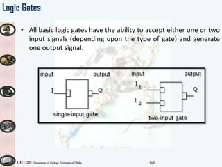
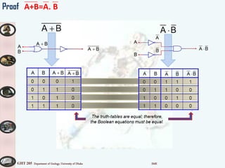
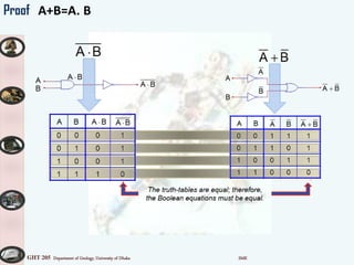
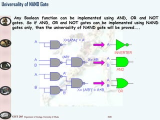
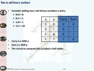
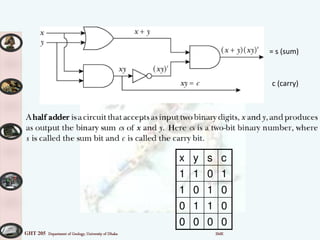
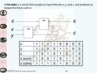
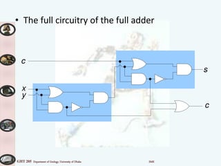
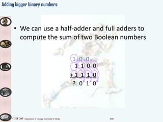
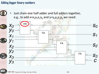
GHT 205 Department of Geology, University of Dhaka SMK
Digital Circuit
Data and control instructions move inside a computer
by means of pulses of electricity. Certain components
of computers combine these pulses following a set of
rules. These components are logic elements.
GHT 205 Department of Geology, University of Dhaka SMK
Logic Gates
• All digital computers for the past 50 years have been
constructed using the same type of components.
• These components are called logic gates.
• Logic gates have been implemented in many different ways.
• Currently, logic gates are most commonly implemented using
electronic VLSI transistor logic.
GHT 205 Department of Geology, University of Dhaka SMK
Logic Gates
• All basic logic gates have the ability to accept either one or two
input signals (depending upon the type of gate) and generate
one output signal.
GHT 205 Department of Geology, University of Dhaka SMK
Logic Gates
• Input and Output signals are binary.
• binary:
– always in one of two possible states;
– typically treated as:
» On / Off (electrically)
» 1 / 0
» True / False
• There is a delay between when a change happens at a
logic gates inputs and when the output changes, called
gate switching time.
• The True or False view is most useful for thinking about
the meaning of the basic logic gates.
GHT 205 Department of Geology, University of Dhaka SMK
Logic Gates
• The Three basic logic gates are:
– AND
– OR
– NOT
• Each of these gates may be drawn in either
– A generic form; or
– An electrical engineering form (more common in text
books)
GHT 205 Department of Geology, University of Dhaka SMK
Logic Gates : AND
The Output signal from an AND gate is True (on, 1) if and
only if both Input signals are True (on, 1).
The Output signal from an AND gate is False (off, 0),
otherwise.
GHT 205 Department of Geology, University of Dhaka SMK
AND gate
•The diagram of the AND gate looks like a capital letter D with two "prongs" on the left
(the inputs) and one "prong" on the right (the output).
•if either of the inputs is 0, then the output of the AND gate is 0. Thus, in order to get an
AND gate to output 1, both inputs to it must be 1
Symbol
Boolean
Algebra
BA
Logic
table/Truth
table
GHT 205 Department of Geology, University of Dhaka SMK
AND Gate:
Behaviour using a Truth Table analysis and an animation.
Truth Table: The table shows that the AND gate responds with a high at the output if the signal applied to the
input A and B are both high.
5v
5v
5v
Input A
Output X
Input B
AND
Animation: In order to see how it works, the gate has been connected to 2 switches and LED. Continue to
see the syste i actio …
Logic 0
Logic 0
Logic 0
Logic 0
Logic 0
Logic 1
Logic 1
Logic 0
Logic 0
Logic 1
Logic 1
Logic 1
A B X
0 0 0
0 1 0
1 0 0
1 1 1
GHT 205 Department of Geology, University of Dhaka SMK
Logic Gate - OR
The Output signal from an OR gate is True (on, 1) if either,
or both, Input signals are True (on, 1).
The Output signal from an OR gate is False (off, 0) if and
only if both Input signals are False (off, 0).
GHT 205 Department of Geology, University of Dhaka SMK
OR gate
•if either of the inputs is 1, then the output of the OR gate is 1. Thus, in
order to get an OR gate to output 0, both inputs to it must be 0
Symbol
Boolean
Algebra
BA
Logic
table
GHT 205 Department of Geology, University of Dhaka SMK
OR Gate
Behaviour using a Truth Table analysis and an animation.
Truth Table: The table shows that the OR gate responds with a high at the output if the signal
applied to the input A or B is high.
Input A
Output X
Input B
OR
5v
5v
5v
Animation: In order to see how it works, the gate has been connected to 2 switches and LED. Continue to
see the syste i actio …
Slide #11
Logic 0
Logic 0
Logic 0
Logic 0
Logic 1
Logic 1
Logic 1
Logic 1
Logic 0
Logic 1
Logic 1
Logic 1
A B X
0 0 0
0 1 1
1 0 1
1 1 1
GHT 205 Department of Geology, University of Dhaka SMK
Logic Gates - NOT
• The Output signal from a NOT gate is True (on, 1) if and
only if the Input signal is False.
• The Output signal from a NOT gate is False (off, 0) if
and only if the Input signal is True.
GHT 205 Department of Geology, University of Dhaka SMK
NOT gate
•The operation of reversing the input state
Symbol
Boolean
Algebra
A
Logic
table
GHT 205 Department of Geology, University of Dhaka SMK
5v
NOT Gate (inverter)
Input A Output X
A X
0 1
1 0
Truth Table: Is a chart that lists the input condition on the left and the gate’s output
response on the right. The table shows that the NOT gate responds at the output
with the inverse of the signal applied to the input.
Animation: In order to see how it works, the gate has been connected to a switch and LED. Continue to see
the syste i actio …
Slide #14
Logic 1
OFF
Logic 0
ON
Logic 1
OFF
Logic 0
ON
Logic 1
OFF
Logic 0
ON
GHT 205 Department of Geology, University of Dhaka SMK
Esho Nije Kori …
a) Draw a circuit : input XY , output X’Y
b) Draw a circuit : input XY , output XY’
a) Draw a circuit : input XY , output X’+Y
b) Draw a circuit : input XY , output X+Y’
GHT 205 Department of Geology, University of Dhaka SMK
Secondary-NAND gate
•The output of the NAND gate is the negation, or reverse of the output
of an AND gate with the same inputs (0 negated equals 1, and 1 negated
equals 0).
Symbol
Boolean
Algebra
BA
Logic
table
GHT 205 Department of Geology, University of Dhaka SMK
Secondary - NOR gate
•NOR stands for "Negated OR". Thus, the output of the NOR gate is
the negation, or reverse of the output of an OR gate with the same
inputs.
Symbol
Boolean
Algebra
BA
Logic
table
GHT 205 Department of Geology, University of Dhaka SMK
Secondary – XOR/EXOR gate
•EOR stands for "Exclusive OR". The thing to remember about EOR gates
is this: An EOR gate will output 1 only if one of the inputs is 1 and the
other input 0. If both inputs are the same (1 and 1, or 0 and 0), then
EOR outputs 0
Symbol
Boolean
Algebra
BA
Logic
table
GHT 205 Department of Geology, University of Dhaka SMK
Boolean Theorem
Boolean theorems are used to simplify or manipulate logic functions.
OR
A+0=A
A+1=1
A+A=A
A+A’=
AND
A.0=0
A.1=A
A.A=A
A.A’=
NOT
A+A’=
A.A’=
A’’=A
DeMorgan’s Theorem
A+B=A. B
A.B= A+ B
GHT 205 Department of Geology, University of Dhaka SMK
Proof A+B=A. B
GHT 205 Department of Geology, University of Dhaka SMK
Proof A+B=A. B
GHT 205 Department of Geology, University of Dhaka SMK
Exercise
=
GHT 205 Department of Geology, University of Dhaka SMK
Universality of NAND Gate
Any Boolean function can be implemented using AND, OR and NOT
gates. So if AND, OR and NOT gates can be implemented using NAND
gates only, then the universality of NAND gate will be proved…..
GHT 205 Department of Geology, University of Dhaka SMK
Universality of NOR Gate
GHT 205 Department of Geology, University of Dhaka SMK
Combinational Logic Using Universal Gates
X = (AB) (CD)
X = (AB) + (CD)
X = (AB) + (CD)
GHT 205 Department of Geology, University of Dhaka SMK
Adders: Logical gates to add two numbers
• We need to use a circuit with more than one output, which clearly more powerful
than a Boolean expression.
GHT 205 Department of Geology, University of Dhaka SMK
How to add binary numbers
• Consider adding two 1-bit binary numbers x and y
 0+0 = 0
 0+1 = 1
 1+0 = 1
 1+1 = 10
• Carry is x AND y
• Sum is x XOR y
• The circuit to compute this is called a half-adder
x y Carry Sum
0 0 0 0
0 1 0 1
1 0 0 1
1 1 1 0
GHT 205 Department of Geology, University of Dhaka SMK
x y s c
1 1 0 1
1 0 1 0
0 1 1 0
0 0 0 0
= s (sum)
c (carry)
GHT 205 Department of Geology, University of Dhaka SMK
x 1 1 1 1 0 0 0 0
y 1 1 0 0 1 1 0 0
c 1 0 1 0 1 0 1 0
s (sum) 1 0 0 1 0 1 1 0
c (carry) 1 1 1 0 1 0 0 0
HAX
Y
S
C
HAX
Y
S
C
x
y
c
c
s
HAX
Y
S
C
HAX
Y
S
C
x
y
c
A full adder is a circuit that accepts as input thee bits x, y, and c, and produces as
output the binary sum cs
GHT 205 Department of Geology, University of Dhaka SMK
• The full circuitry of the full adder
x
y
s
c
c
GHT 205 Department of Geology, University of Dhaka SMK
• We can use a half-adder and full adders to
compute the sum of two Boolean numbers
1 1 0 0
+ 1 1 1 0
010?
001
Adding bigger binary numbers
GHT 205 Department of Geology, University of Dhaka SMK
Adding bigger binary numbers
• Just chain one half adder and full adders together,
e.g., to add x=x3x2x1x0 and y=y3y2y1y0 we need:
HAX
Y
S
C
FAC
Y
X
S
C
FAC
Y
X
S
C
FAC
Y
X
S
C
x1
y1
x2
y2
x3
y3
x0
y0
s0
s1
s2
s3
c
GHT 205 Department of Geology, University of Dhaka SMK
Adding bigger binary numbers
• A half adder has 4 logic gates
• A full adder has two half adders plus a OR gate
– Total of 9 logic gates
• To add n bit binary numbers, you need 1 HA and n-1 FAs
• To add 32 bit binary numbers, you need 1 HA and 31 FAs
– Total of 4+9*31 = 283 logic gates
• To add 64 bit binary numbers, you need 1 HA and 63 FAs
– Total of 4+9*63 = 571 logic gates
GHT 205 Department of Geology, University of Dhaka SMK
More about logic gates
• To implement a logic gate in hardware, you use a transistor
• Transistors are all enclosed in an IC , or integrated circuit
• The current Intel Pentium IV processors have 55 million
transistors!

Logic gate

  • 1.
    GHT 205 Departmentof Geology, University of Dhaka SMK Digital Circuit Data and control instructions move inside a computer by means of pulses of electricity. Certain components of computers combine these pulses following a set of rules. These components are logic elements.
  • 2.
    GHT 205 Departmentof Geology, University of Dhaka SMK Logic Gates • All digital computers for the past 50 years have been constructed using the same type of components. • These components are called logic gates. • Logic gates have been implemented in many different ways. • Currently, logic gates are most commonly implemented using electronic VLSI transistor logic.
  • 3.
    GHT 205 Departmentof Geology, University of Dhaka SMK Logic Gates • All basic logic gates have the ability to accept either one or two input signals (depending upon the type of gate) and generate one output signal.
  • 4.
    GHT 205 Departmentof Geology, University of Dhaka SMK Logic Gates • Input and Output signals are binary. • binary: – always in one of two possible states; – typically treated as: » On / Off (electrically) » 1 / 0 » True / False • There is a delay between when a change happens at a logic gates inputs and when the output changes, called gate switching time. • The True or False view is most useful for thinking about the meaning of the basic logic gates.
  • 5.
    GHT 205 Departmentof Geology, University of Dhaka SMK Logic Gates • The Three basic logic gates are: – AND – OR – NOT • Each of these gates may be drawn in either – A generic form; or – An electrical engineering form (more common in text books)
  • 6.
    GHT 205 Departmentof Geology, University of Dhaka SMK Logic Gates : AND The Output signal from an AND gate is True (on, 1) if and only if both Input signals are True (on, 1). The Output signal from an AND gate is False (off, 0), otherwise.
  • 7.
    GHT 205 Departmentof Geology, University of Dhaka SMK AND gate •The diagram of the AND gate looks like a capital letter D with two "prongs" on the left (the inputs) and one "prong" on the right (the output). •if either of the inputs is 0, then the output of the AND gate is 0. Thus, in order to get an AND gate to output 1, both inputs to it must be 1 Symbol Boolean Algebra BA Logic table/Truth table
  • 8.
    GHT 205 Departmentof Geology, University of Dhaka SMK AND Gate: Behaviour using a Truth Table analysis and an animation. Truth Table: The table shows that the AND gate responds with a high at the output if the signal applied to the input A and B are both high. 5v 5v 5v Input A Output X Input B AND Animation: In order to see how it works, the gate has been connected to 2 switches and LED. Continue to see the syste i actio … Logic 0 Logic 0 Logic 0 Logic 0 Logic 0 Logic 1 Logic 1 Logic 0 Logic 0 Logic 1 Logic 1 Logic 1 A B X 0 0 0 0 1 0 1 0 0 1 1 1
  • 9.
    GHT 205 Departmentof Geology, University of Dhaka SMK Logic Gate - OR The Output signal from an OR gate is True (on, 1) if either, or both, Input signals are True (on, 1). The Output signal from an OR gate is False (off, 0) if and only if both Input signals are False (off, 0).
  • 10.
    GHT 205 Departmentof Geology, University of Dhaka SMK OR gate •if either of the inputs is 1, then the output of the OR gate is 1. Thus, in order to get an OR gate to output 0, both inputs to it must be 0 Symbol Boolean Algebra BA Logic table
  • 11.
    GHT 205 Departmentof Geology, University of Dhaka SMK OR Gate Behaviour using a Truth Table analysis and an animation. Truth Table: The table shows that the OR gate responds with a high at the output if the signal applied to the input A or B is high. Input A Output X Input B OR 5v 5v 5v Animation: In order to see how it works, the gate has been connected to 2 switches and LED. Continue to see the syste i actio … Slide #11 Logic 0 Logic 0 Logic 0 Logic 0 Logic 1 Logic 1 Logic 1 Logic 1 Logic 0 Logic 1 Logic 1 Logic 1 A B X 0 0 0 0 1 1 1 0 1 1 1 1
  • 12.
    GHT 205 Departmentof Geology, University of Dhaka SMK Logic Gates - NOT • The Output signal from a NOT gate is True (on, 1) if and only if the Input signal is False. • The Output signal from a NOT gate is False (off, 0) if and only if the Input signal is True.
  • 13.
    GHT 205 Departmentof Geology, University of Dhaka SMK NOT gate •The operation of reversing the input state Symbol Boolean Algebra A Logic table
  • 14.
    GHT 205 Departmentof Geology, University of Dhaka SMK 5v NOT Gate (inverter) Input A Output X A X 0 1 1 0 Truth Table: Is a chart that lists the input condition on the left and the gate’s output response on the right. The table shows that the NOT gate responds at the output with the inverse of the signal applied to the input. Animation: In order to see how it works, the gate has been connected to a switch and LED. Continue to see the syste i actio … Slide #14 Logic 1 OFF Logic 0 ON Logic 1 OFF Logic 0 ON Logic 1 OFF Logic 0 ON
  • 15.
    GHT 205 Departmentof Geology, University of Dhaka SMK Esho Nije Kori … a) Draw a circuit : input XY , output X’Y b) Draw a circuit : input XY , output XY’ a) Draw a circuit : input XY , output X’+Y b) Draw a circuit : input XY , output X+Y’
  • 16.
    GHT 205 Departmentof Geology, University of Dhaka SMK Secondary-NAND gate •The output of the NAND gate is the negation, or reverse of the output of an AND gate with the same inputs (0 negated equals 1, and 1 negated equals 0). Symbol Boolean Algebra BA Logic table
  • 17.
    GHT 205 Departmentof Geology, University of Dhaka SMK Secondary - NOR gate •NOR stands for "Negated OR". Thus, the output of the NOR gate is the negation, or reverse of the output of an OR gate with the same inputs. Symbol Boolean Algebra BA Logic table
  • 18.
    GHT 205 Departmentof Geology, University of Dhaka SMK Secondary – XOR/EXOR gate •EOR stands for "Exclusive OR". The thing to remember about EOR gates is this: An EOR gate will output 1 only if one of the inputs is 1 and the other input 0. If both inputs are the same (1 and 1, or 0 and 0), then EOR outputs 0 Symbol Boolean Algebra BA Logic table
  • 19.
    GHT 205 Departmentof Geology, University of Dhaka SMK Boolean Theorem Boolean theorems are used to simplify or manipulate logic functions. OR A+0=A A+1=1 A+A=A A+A’= AND A.0=0 A.1=A A.A=A A.A’= NOT A+A’= A.A’= A’’=A DeMorgan’s Theorem A+B=A. B A.B= A+ B
  • 20.
    GHT 205 Departmentof Geology, University of Dhaka SMK Proof A+B=A. B
  • 21.
    GHT 205 Departmentof Geology, University of Dhaka SMK Proof A+B=A. B
  • 22.
    GHT 205 Departmentof Geology, University of Dhaka SMK Exercise =
  • 23.
    GHT 205 Departmentof Geology, University of Dhaka SMK Universality of NAND Gate Any Boolean function can be implemented using AND, OR and NOT gates. So if AND, OR and NOT gates can be implemented using NAND gates only, then the universality of NAND gate will be proved…..
  • 24.
    GHT 205 Departmentof Geology, University of Dhaka SMK Universality of NOR Gate
  • 25.
    GHT 205 Departmentof Geology, University of Dhaka SMK Combinational Logic Using Universal Gates X = (AB) (CD) X = (AB) + (CD) X = (AB) + (CD)
  • 26.
    GHT 205 Departmentof Geology, University of Dhaka SMK
  • 27.
    GHT 205 Departmentof Geology, University of Dhaka SMK Adders: Logical gates to add two numbers • We need to use a circuit with more than one output, which clearly more powerful than a Boolean expression.
  • 28.
    GHT 205 Departmentof Geology, University of Dhaka SMK How to add binary numbers • Consider adding two 1-bit binary numbers x and y  0+0 = 0  0+1 = 1  1+0 = 1  1+1 = 10 • Carry is x AND y • Sum is x XOR y • The circuit to compute this is called a half-adder x y Carry Sum 0 0 0 0 0 1 0 1 1 0 0 1 1 1 1 0
  • 29.
    GHT 205 Departmentof Geology, University of Dhaka SMK x y s c 1 1 0 1 1 0 1 0 0 1 1 0 0 0 0 0 = s (sum) c (carry)
  • 30.
    GHT 205 Departmentof Geology, University of Dhaka SMK x 1 1 1 1 0 0 0 0 y 1 1 0 0 1 1 0 0 c 1 0 1 0 1 0 1 0 s (sum) 1 0 0 1 0 1 1 0 c (carry) 1 1 1 0 1 0 0 0 HAX Y S C HAX Y S C x y c c s HAX Y S C HAX Y S C x y c A full adder is a circuit that accepts as input thee bits x, y, and c, and produces as output the binary sum cs
  • 31.
    GHT 205 Departmentof Geology, University of Dhaka SMK • The full circuitry of the full adder x y s c c
  • 32.
    GHT 205 Departmentof Geology, University of Dhaka SMK • We can use a half-adder and full adders to compute the sum of two Boolean numbers 1 1 0 0 + 1 1 1 0 010? 001 Adding bigger binary numbers
  • 33.
    GHT 205 Departmentof Geology, University of Dhaka SMK Adding bigger binary numbers • Just chain one half adder and full adders together, e.g., to add x=x3x2x1x0 and y=y3y2y1y0 we need: HAX Y S C FAC Y X S C FAC Y X S C FAC Y X S C x1 y1 x2 y2 x3 y3 x0 y0 s0 s1 s2 s3 c
  • 34.
    GHT 205 Departmentof Geology, University of Dhaka SMK Adding bigger binary numbers • A half adder has 4 logic gates • A full adder has two half adders plus a OR gate – Total of 9 logic gates • To add n bit binary numbers, you need 1 HA and n-1 FAs • To add 32 bit binary numbers, you need 1 HA and 31 FAs – Total of 4+9*31 = 283 logic gates • To add 64 bit binary numbers, you need 1 HA and 63 FAs – Total of 4+9*63 = 571 logic gates
  • 35.
    GHT 205 Departmentof Geology, University of Dhaka SMK More about logic gates • To implement a logic gate in hardware, you use a transistor • Transistors are all enclosed in an IC , or integrated circuit • The current Intel Pentium IV processors have 55 million transistors!