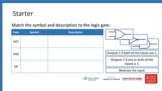
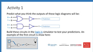
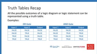
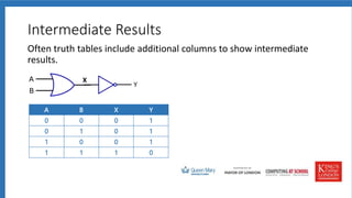
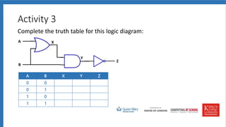
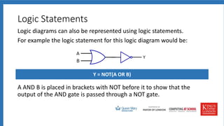
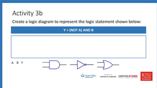
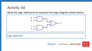
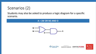
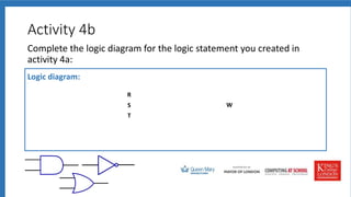
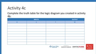
Session 2
Theory: Truth Tables / Logic Diagrams
Practical: For and While Loops
Teaching Computing
Specification Content
OCR
• Simple logic diagrams using the operations AND, OR and NOT
• Truth tables
• Combining Boolean operators using AND, OR and NOT to two levels
• Applying logical operators in appropriate truth tables to solve problems.
AQA
• Be able to construct truth tables for the following logic gates: NOT, AND, OR
• Construct truth tables for simple logic circuits
• Interpret the results of simple truth tables
• Create, modify and interpret simple logic circuit diagrams.
Edexcel
• Be able to construct truth tables for a given logic statement (AND, OR, NOT)
• Be able to produce logic statements for a given problem.
Starter
Match the symbol and description to the logic gate:
Gate Symbol Description
NOT
AND
OR
Reverses the input.
Outputs 1 if one or both of the
inputs is 1.
Outputs 1 if both of the inputs are 1.
What’s the Output?
1
1
0
?
0
1
A
1
1
0
1
?
B
1
1 ?
C
1
1
0
?
1
D
Combining Logic Gates
We combine logic gates in order to build logic circuits.
For example:
Activity 1
Predict what you think the outputs of these logic diagrams will be:
Build these circuits in the logic.ly simulator to test your predictions. An
example of the first circuit is show here:
1
1
0
1
1
1
0
1
Prediction:
Prediction:
Truth Tables Recap
All the possible outcomes of a logic diagram or logic statement can be
represented using a truth table.
Examples:
Input 1 Input 2 Output
0 0 0
0 1 0
1 0 0
1 1 1
Input 1 Input 2 Output
0 0 0
0 1 1
1 0 1
1 1 1
OR Gate AND Gate
Input 1 Input 2 Output
FALSE FALSE FALSE
FALSE TRUE FALSE
TRUE FALSE FALSE
TRUE TRUE TRUE
Input 1 Input 2 Output
FALSE FALSE FALSE
FALSE TRUE TRUE
TRUE FALSE TRUE
TRUE TRUE TRUE
Activity 2
Complete this interactive truth tables activity:
Intermediate Results
Often truth tables include additional columns to show intermediate
results.
A B X Y
0 0 0 1
0 1 0 1
1 0 0 1
1 1 1 0
X
Activity 3
Complete the truth table for this logic diagram:
A B X Y Z
0 0
0 1
1 0
1 1
A
B
X
Y
Z
Logic Statements
Logic diagrams can also be represented using logic statements.
For example the logic statement for this logic diagram would be:
A AND B is placed in brackets with NOT before it to show that the
output of the AND gate is passed through a NOT gate.
Y = NOT(A OR B)
Activity 3a
Create a logic diagram to represent the logic statement shown below:
Y = NOT(A AND B)
Activity 3b
Create a logic diagram to represent the logic statement shown below:
Y = (NOT A) AND B
Activity 3c
Write the logic statement to represent the logic diagram shown below:
Logic statement:
Activity 3d
Write the logic statement to represent the logic diagram shown below:
Logic statement:
C
D
Scenarios (1)
Sometimes students may be asked to produce a logic statement for a
specific scenario.
Example
A car alarm (A) is set off if a window (W) is broken or if it senses something moving
(M) inside the car, and if the alarm is on (O) .
Give the logic statement the microcontroller uses to determine if the car alarm
should be sounded.
A = (W OR M) AND O
Scenarios (2)
Students may also be asked to produce a logic diagram for a specific
scenario.
A = (W OR M) AND O
W
M
O
A
Scenarios (3)
Students could also be asked to produce a truth table for a logic
statement that relates to a specific scenario.
A = (W OR M) AND O
INPUTS OUTPUT
W M O A
0 0 0 0
0 0 1 0
0 1 0 0
1 1 1 1
1 0 0 0
1 0 1 1
1 1 0 0
1 1 1 1
Activity 4a
Write the logic statement for this scenario:
An automated weather station monitors rain fall (R), wind speed (S) and
temperature (T). It generates a warning (W) if any of the readings are outside set
limits.
Logic statement:
Activity 4b
Complete the logic diagram for the logic statement you created in
activity 4a:
Logic diagram:
R
S
T
W
Activity 4c
Complete the truth table for the logic diagram you created in activity
4b:
INPUTS OUTPUT
R S T W

Logic Gate.pptx

  • 1.
    Session 2 Theory: TruthTables / Logic Diagrams Practical: For and While Loops Teaching Computing
  • 2.
    Specification Content OCR • Simplelogic diagrams using the operations AND, OR and NOT • Truth tables • Combining Boolean operators using AND, OR and NOT to two levels • Applying logical operators in appropriate truth tables to solve problems. AQA • Be able to construct truth tables for the following logic gates: NOT, AND, OR • Construct truth tables for simple logic circuits • Interpret the results of simple truth tables • Create, modify and interpret simple logic circuit diagrams. Edexcel • Be able to construct truth tables for a given logic statement (AND, OR, NOT) • Be able to produce logic statements for a given problem.
  • 3.
    Starter Match the symboland description to the logic gate: Gate Symbol Description NOT AND OR Reverses the input. Outputs 1 if one or both of the inputs is 1. Outputs 1 if both of the inputs are 1.
  • 4.
  • 5.
    Combining Logic Gates Wecombine logic gates in order to build logic circuits. For example:
  • 6.
    Activity 1 Predict whatyou think the outputs of these logic diagrams will be: Build these circuits in the logic.ly simulator to test your predictions. An example of the first circuit is show here: 1 1 0 1 1 1 0 1 Prediction: Prediction:
  • 7.
    Truth Tables Recap Allthe possible outcomes of a logic diagram or logic statement can be represented using a truth table. Examples: Input 1 Input 2 Output 0 0 0 0 1 0 1 0 0 1 1 1 Input 1 Input 2 Output 0 0 0 0 1 1 1 0 1 1 1 1 OR Gate AND Gate Input 1 Input 2 Output FALSE FALSE FALSE FALSE TRUE FALSE TRUE FALSE FALSE TRUE TRUE TRUE Input 1 Input 2 Output FALSE FALSE FALSE FALSE TRUE TRUE TRUE FALSE TRUE TRUE TRUE TRUE
  • 8.
    Activity 2 Complete thisinteractive truth tables activity:
  • 9.
    Intermediate Results Often truthtables include additional columns to show intermediate results. A B X Y 0 0 0 1 0 1 0 1 1 0 0 1 1 1 1 0 X
  • 10.
    Activity 3 Complete thetruth table for this logic diagram: A B X Y Z 0 0 0 1 1 0 1 1 A B X Y Z
  • 11.
    Logic Statements Logic diagramscan also be represented using logic statements. For example the logic statement for this logic diagram would be: A AND B is placed in brackets with NOT before it to show that the output of the AND gate is passed through a NOT gate. Y = NOT(A OR B)
  • 12.
    Activity 3a Create alogic diagram to represent the logic statement shown below: Y = NOT(A AND B)
  • 13.
    Activity 3b Create alogic diagram to represent the logic statement shown below: Y = (NOT A) AND B
  • 14.
    Activity 3c Write thelogic statement to represent the logic diagram shown below: Logic statement:
  • 15.
    Activity 3d Write thelogic statement to represent the logic diagram shown below: Logic statement: C D
  • 16.
    Scenarios (1) Sometimes studentsmay be asked to produce a logic statement for a specific scenario. Example A car alarm (A) is set off if a window (W) is broken or if it senses something moving (M) inside the car, and if the alarm is on (O) . Give the logic statement the microcontroller uses to determine if the car alarm should be sounded. A = (W OR M) AND O
  • 17.
    Scenarios (2) Students mayalso be asked to produce a logic diagram for a specific scenario. A = (W OR M) AND O W M O A
  • 18.
    Scenarios (3) Students couldalso be asked to produce a truth table for a logic statement that relates to a specific scenario. A = (W OR M) AND O INPUTS OUTPUT W M O A 0 0 0 0 0 0 1 0 0 1 0 0 1 1 1 1 1 0 0 0 1 0 1 1 1 1 0 0 1 1 1 1
  • 19.
    Activity 4a Write thelogic statement for this scenario: An automated weather station monitors rain fall (R), wind speed (S) and temperature (T). It generates a warning (W) if any of the readings are outside set limits. Logic statement:
  • 20.
    Activity 4b Complete thelogic diagram for the logic statement you created in activity 4a: Logic diagram: R S T W
  • 21.
    Activity 4c Complete thetruth table for the logic diagram you created in activity 4b: INPUTS OUTPUT R S T W