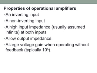
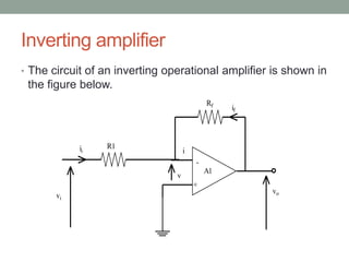
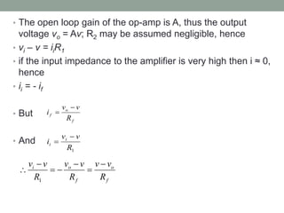
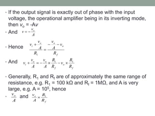
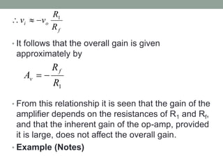
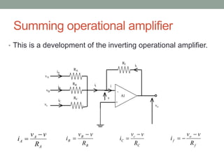
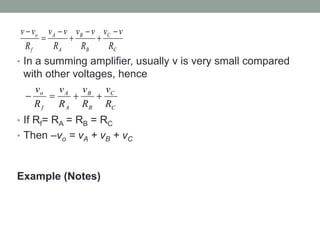
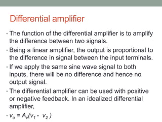
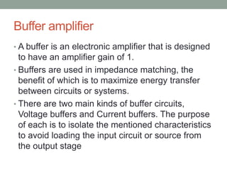
SIGNAL CONDITIONING
AND CONVERSION
Process and Instrumentation
Lerotholi Polytechnic
© December 2012
Learning outcomes
• Outline the functions of the signal conditioning
circuits
• State the operational amplifiers’ properties
• Analyse different operational amplifier
configurations
Functions of signal conditioning circuits
• Amplification - It is the process of linearly
increasing the amplitude of an electrical signal.
• Attenuation - It is the gradual loss in strength of
any kind of signal through a medium.
• Filtering - It is the removal of unwanted
components from the signal.
• Conversion - This can mean making the signal
into d.c voltage and/or current
Operational amplifiers
• The basis of many signal conditioning modules is
the operational amplifier.
• The common IC operational amplifier is one
which has a very high gain
• Its applications are not limited to linear
amplification systems, but include digital logic
systems as well.
Properties of operational amplifiers
• An inverting input
• A non-inverting input
• A high input impedance (usually assumed
infinite) at both inputs
• A low output impedance
• A large voltage gain when operating without
feedback (typically 105)
• The voltage gain remains constant over a
wide frequency range.
• Relatively free of drift due to ambient
temperature change, hence the direct
voltage output is zero when there is no input
signal.
• Good stability, being free of parasitic
oscillation.
Operational amplifiers’ configurations
• The basic unit performs in a variety of ways
according to the manner of the surrounding
circuitry
• A number of general applications are as
follows:
• Inverting amplifier
• Differential amplifier
• Summing amplifier
• Buffer amplifier
Inverting amplifier
• The circuit of an inverting operational amplifier is shown in
the figure below.
-
+
Rf
A1
R1
vi
i
v
if
vo
ii
• The open loop gain of the op-amp is A, thus the output
voltage vo = Av; R2 may be assumed negligible, hence
• vi – v = iiR1
• if the input impedance to the amplifier is very high then i ≈ 0,
hence
• ii = - if
• But
• And
f
o
f
R
v
v
i


1
R
v
v
i i
i


f
o
f
o
i
R
v
v
R
v
v
R
v
v 






1
• If the output signal is exactly out of phase with the input
voltage, the operational amplifier being in its inverting mode,
then vo = -Av
• And
• Hence
• And
• Generally, R1 and Rf are of approximately the same range of
resistance, e.g. R1 = 100 kΩ and Rf = 1MΩ, and A is very
large, e.g. A = 105, hence
• and
A
v
v o


f
o
o
o
i
R
v
A
v
R
A
v
v 



1
f
o
f
o
o
i
R
R
v
R
R
A
v
A
v
v 1
1






A
vo
f
o
R
R
A
v 1

• It follows that the overall gain is given
approximately by
• From this relationship it is seen that the gain of the
amplifier depends on the resistances of R1 and Rf,
and that the inherent gain of the op-amp, provided
it is large, does not affect the overall gain.
• Example (Notes)
f
o
i
R
R
v
v 1



1
R
R
A
f
v 

Summing operational amplifier
• This is a development of the inverting operational amplifier.
-
+
Rf
A1
RA
RB
RC
iC
vc
iB
iA
vA
vB
ii i
v
if
vo
A
A
A
R
v
v
i


B
B
B
R
v
v
i


C
c
C
R
v
v
i


f
o
f
R
v
v
i



• In a summing amplifier, usually v is very small compared
with other voltages, hence
• If Rf= RA = RB = RC
• Then –vo = vA + vB + vC
Example (Notes)
C
C
B
B
A
A
f
o
R
v
v
R
v
v
R
v
v
R
v
v 






C
C
B
B
A
A
f
o
R
v
R
v
R
v
R
v




Differential amplifier
• The function of the differential amplifier is to amplify
the difference between two signals.
• Being a linear amplifier, the output is proportional to
the difference in signal between the input terminals.
• If we apply the same sine wave signal to both
inputs, there will be no difference and hence no
output signal.
• The differential amplifier can be used with positive
or negative feedback. In an idealized differential
amplifier,
• vo = Av(v1 - v2 )
Buffer amplifier
• A buffer is an electronic amplifier that is designed
to have an amplifier gain of 1.
• Buffers are used in impedance matching, the
benefit of which is to maximize energy transfer
between circuits or systems.
• There are two main kinds of buffer circuits,
Voltage buffers and Current buffers. The purpose
of each is to isolate the mentioned characteristics
to avoid loading the input circuit or source from
the output stage

Lesson # 9 - Signal conditioning and conversion.pdf

  • 1.
    SIGNAL CONDITIONING AND CONVERSION Processand Instrumentation Lerotholi Polytechnic © December 2012
  • 2.
    Learning outcomes • Outlinethe functions of the signal conditioning circuits • State the operational amplifiers’ properties • Analyse different operational amplifier configurations
  • 3.
    Functions of signalconditioning circuits • Amplification - It is the process of linearly increasing the amplitude of an electrical signal. • Attenuation - It is the gradual loss in strength of any kind of signal through a medium. • Filtering - It is the removal of unwanted components from the signal. • Conversion - This can mean making the signal into d.c voltage and/or current
  • 4.
    Operational amplifiers • Thebasis of many signal conditioning modules is the operational amplifier. • The common IC operational amplifier is one which has a very high gain • Its applications are not limited to linear amplification systems, but include digital logic systems as well.
  • 5.
    Properties of operationalamplifiers • An inverting input • A non-inverting input • A high input impedance (usually assumed infinite) at both inputs • A low output impedance • A large voltage gain when operating without feedback (typically 105)
  • 6.
    • The voltagegain remains constant over a wide frequency range. • Relatively free of drift due to ambient temperature change, hence the direct voltage output is zero when there is no input signal. • Good stability, being free of parasitic oscillation.
  • 7.
    Operational amplifiers’ configurations •The basic unit performs in a variety of ways according to the manner of the surrounding circuitry • A number of general applications are as follows: • Inverting amplifier • Differential amplifier • Summing amplifier • Buffer amplifier
  • 8.
    Inverting amplifier • Thecircuit of an inverting operational amplifier is shown in the figure below. - + Rf A1 R1 vi i v if vo ii
  • 9.
    • The openloop gain of the op-amp is A, thus the output voltage vo = Av; R2 may be assumed negligible, hence • vi – v = iiR1 • if the input impedance to the amplifier is very high then i ≈ 0, hence • ii = - if • But • And f o f R v v i   1 R v v i i i   f o f o i R v v R v v R v v        1
  • 10.
    • If theoutput signal is exactly out of phase with the input voltage, the operational amplifier being in its inverting mode, then vo = -Av • And • Hence • And • Generally, R1 and Rf are of approximately the same range of resistance, e.g. R1 = 100 kΩ and Rf = 1MΩ, and A is very large, e.g. A = 105, hence • and A v v o   f o o o i R v A v R A v v     1 f o f o o i R R v R R A v A v v 1 1       A vo f o R R A v 1 
  • 11.
    • It followsthat the overall gain is given approximately by • From this relationship it is seen that the gain of the amplifier depends on the resistances of R1 and Rf, and that the inherent gain of the op-amp, provided it is large, does not affect the overall gain. • Example (Notes) f o i R R v v 1    1 R R A f v  
  • 12.
    Summing operational amplifier •This is a development of the inverting operational amplifier. - + Rf A1 RA RB RC iC vc iB iA vA vB ii i v if vo A A A R v v i   B B B R v v i   C c C R v v i   f o f R v v i   
  • 13.
    • In asumming amplifier, usually v is very small compared with other voltages, hence • If Rf= RA = RB = RC • Then –vo = vA + vB + vC Example (Notes) C C B B A A f o R v v R v v R v v R v v        C C B B A A f o R v R v R v R v    
  • 14.
    Differential amplifier • Thefunction of the differential amplifier is to amplify the difference between two signals. • Being a linear amplifier, the output is proportional to the difference in signal between the input terminals. • If we apply the same sine wave signal to both inputs, there will be no difference and hence no output signal. • The differential amplifier can be used with positive or negative feedback. In an idealized differential amplifier, • vo = Av(v1 - v2 )
  • 15.
    Buffer amplifier • Abuffer is an electronic amplifier that is designed to have an amplifier gain of 1. • Buffers are used in impedance matching, the benefit of which is to maximize energy transfer between circuits or systems. • There are two main kinds of buffer circuits, Voltage buffers and Current buffers. The purpose of each is to isolate the mentioned characteristics to avoid loading the input circuit or source from the output stage