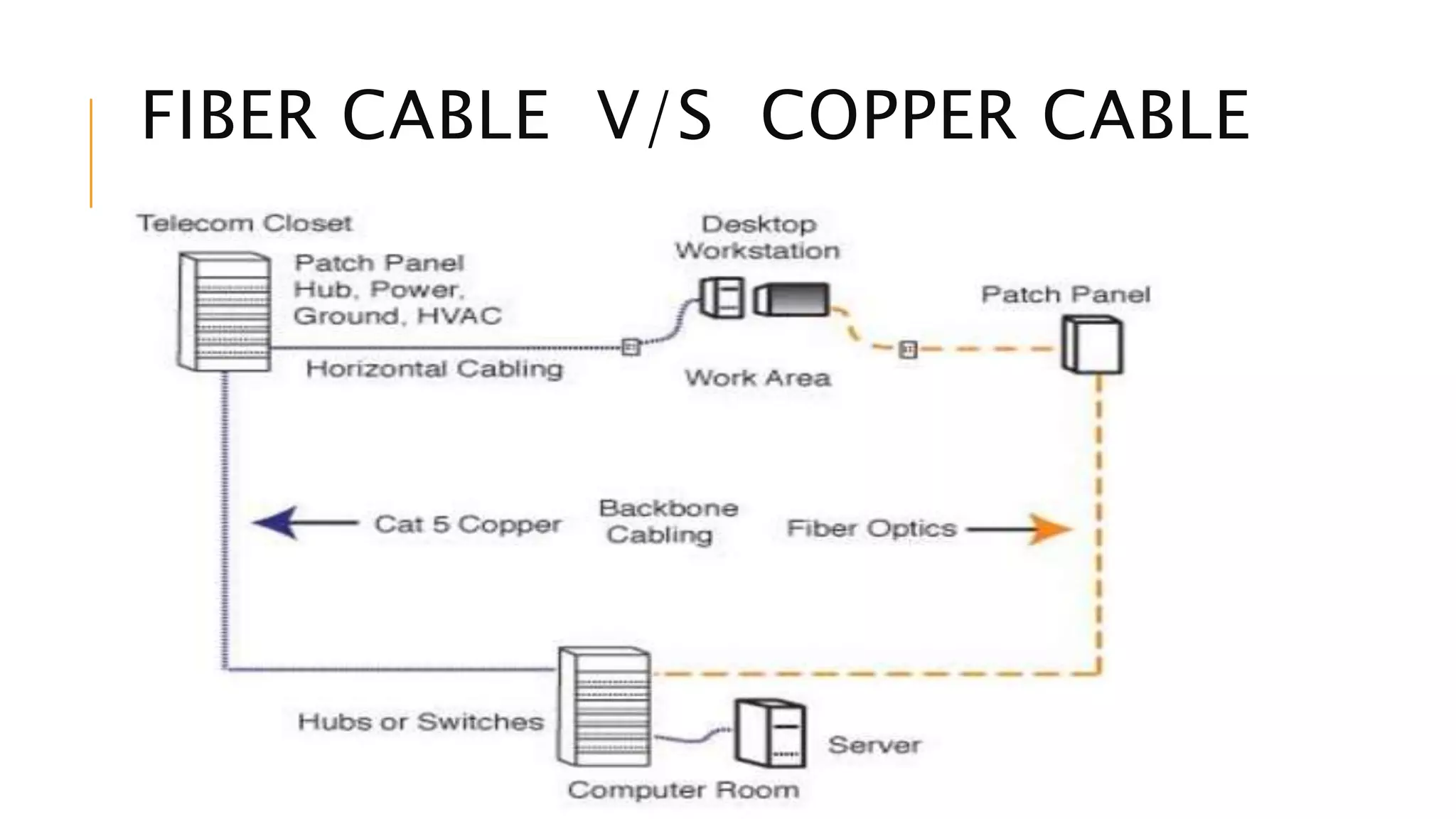
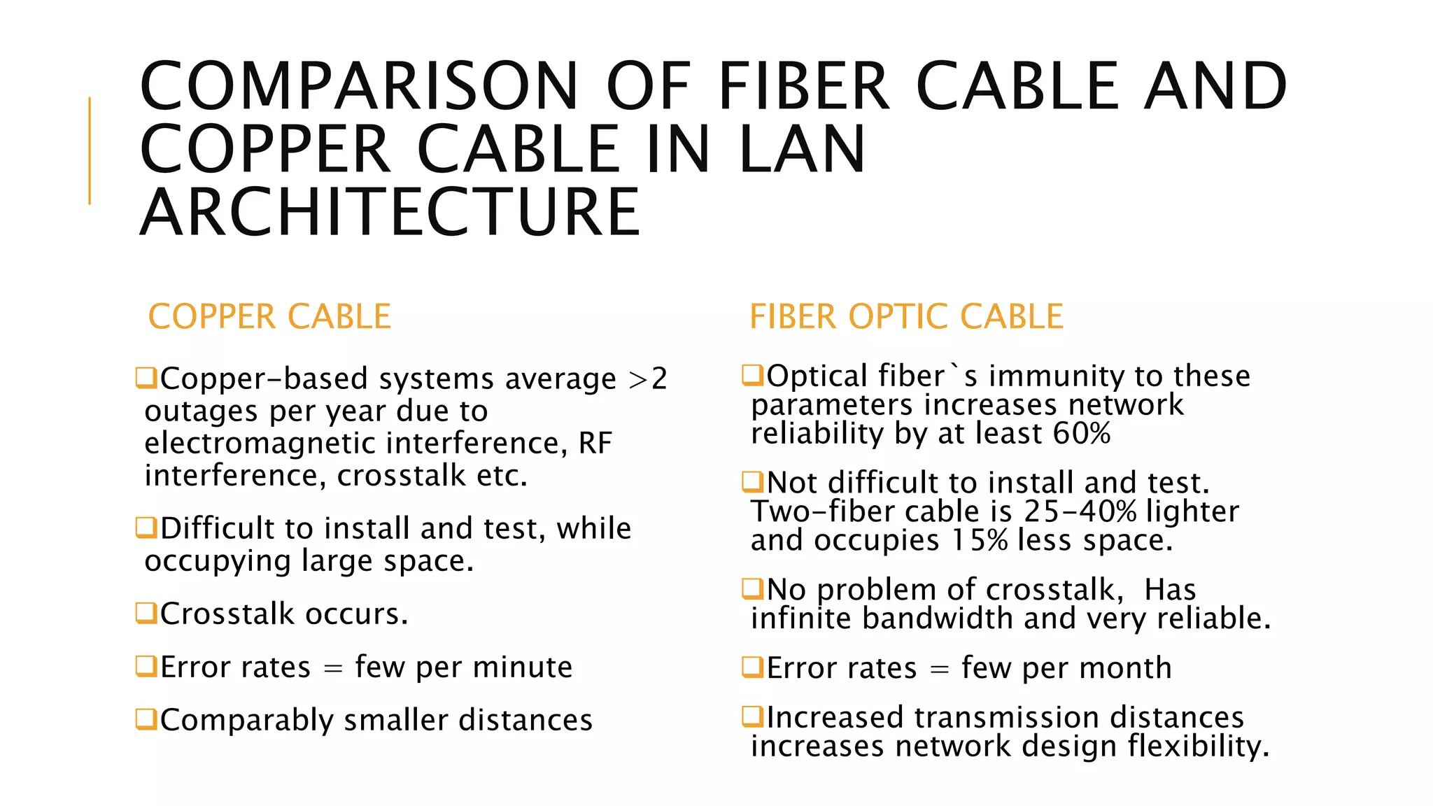
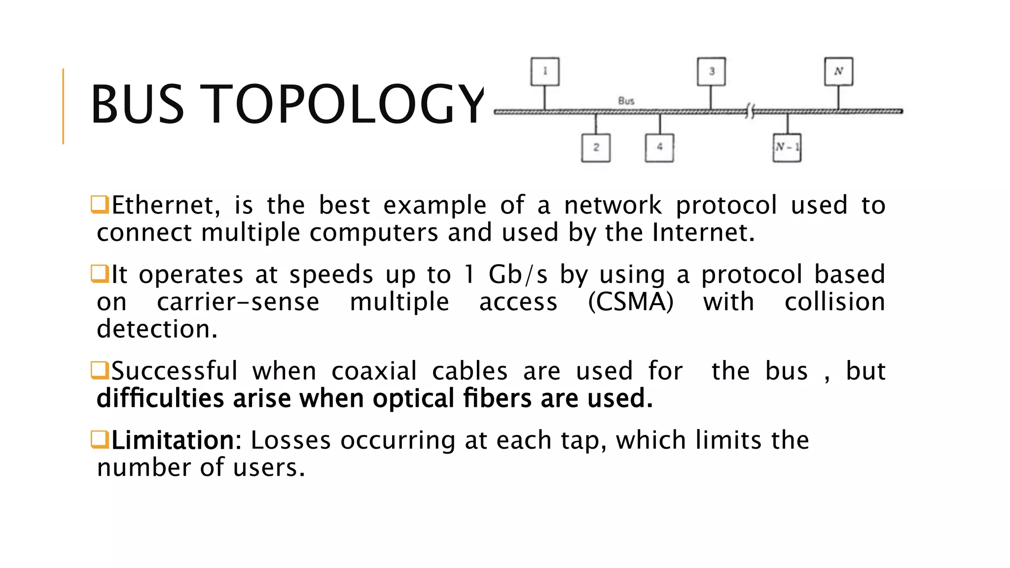
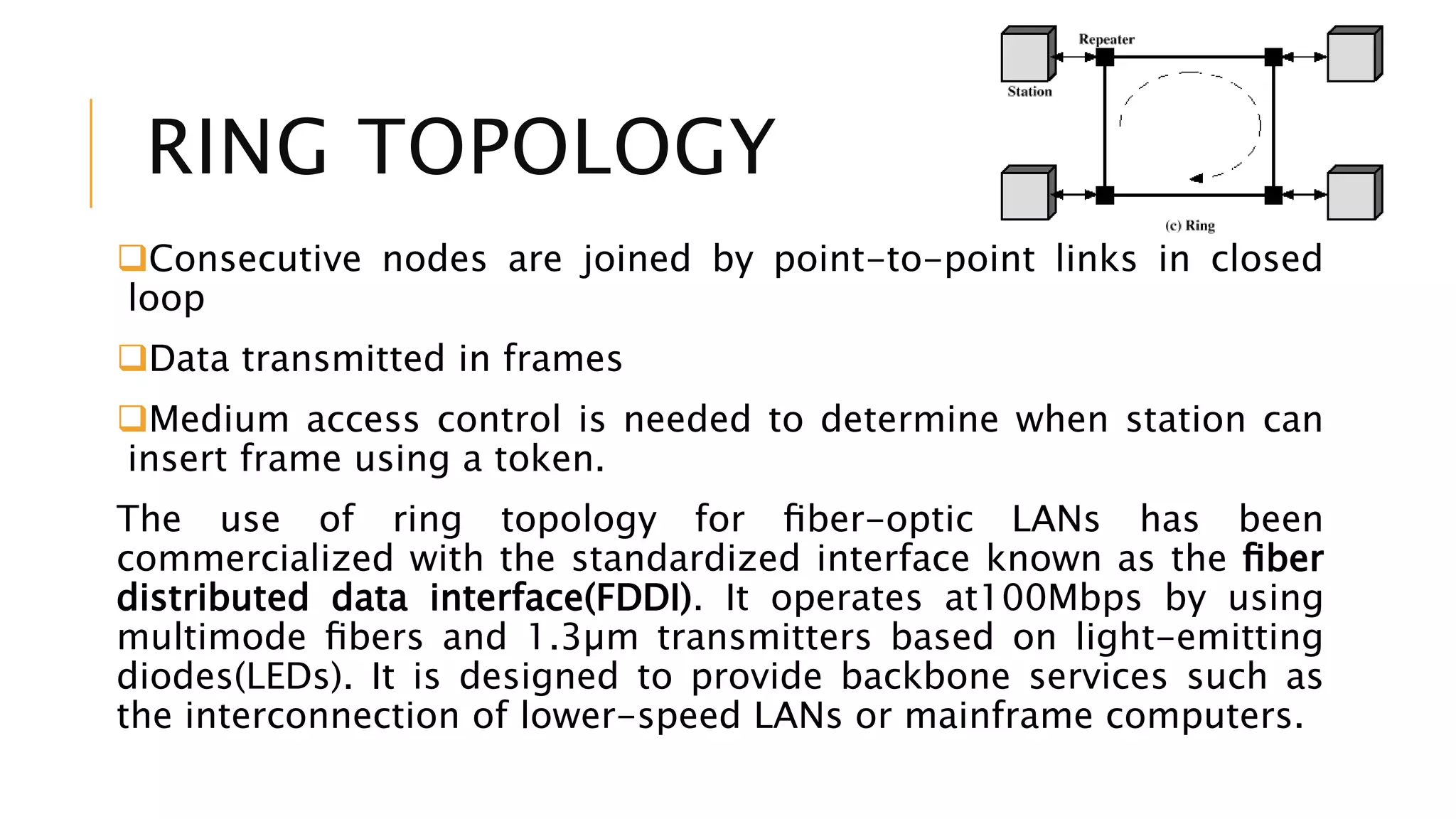
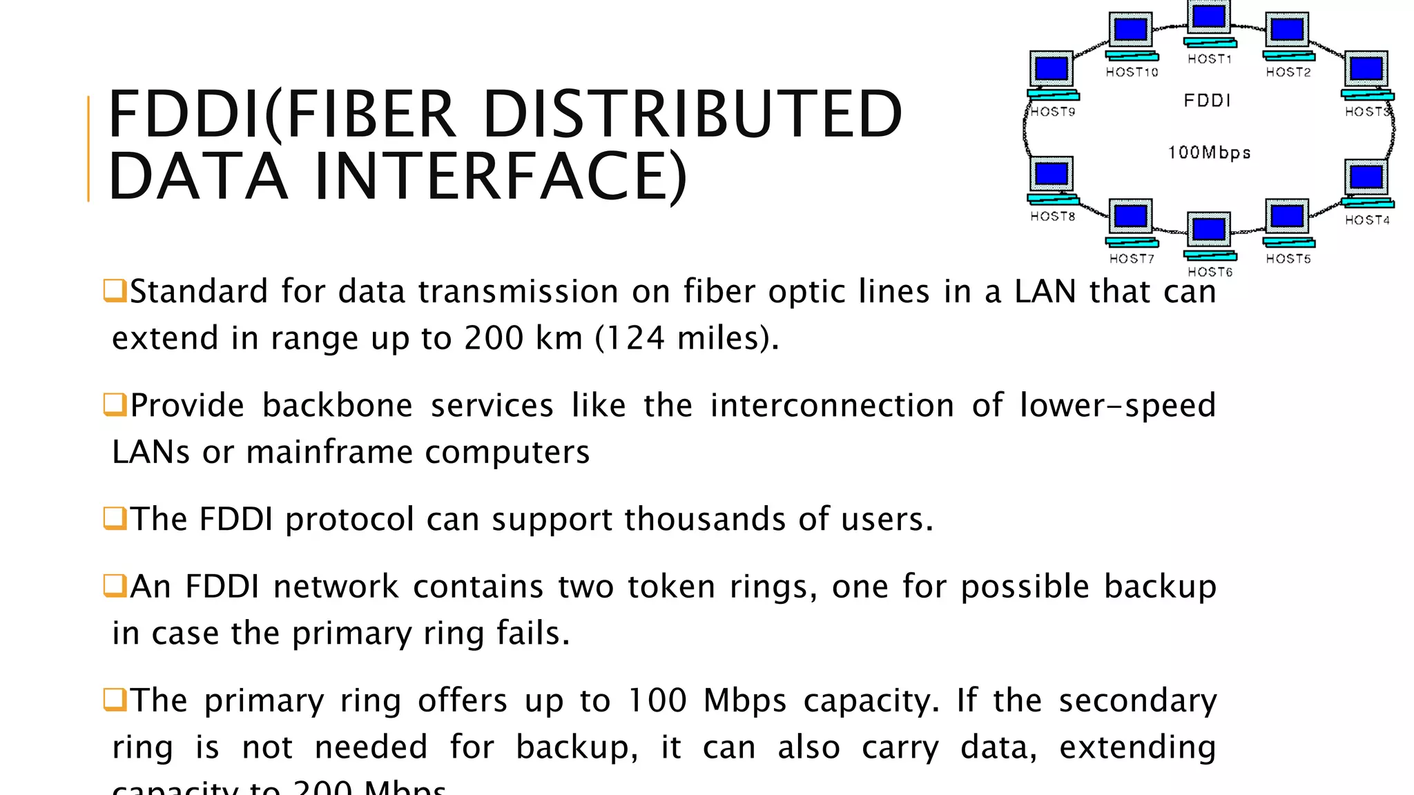
LOCAL AREA
NETWORKArchitecture
Presented By:
Ayushi Gagneja
HOW CAN I CONNECT TWO
PC’S ?
LAN - LOCAL AREA
NETWORKS
Many applications of fiber-optic communication require networks
with a large number of users within a local area such that any user
can access the network randomly to transmit data to any other user.
Group of computers and associated devices that share common
communications line.
LAN systems are used by colleges, universities, office buildings, and
industrial plants, for making use of optical fiber.
Due to small transmission distances (<10 km), fiber losses are less.
Main advantage of using optical fibers is the large bandwidth
offered by OFC systems.
FIBER CABLE V/S COPPER CABLE
COMPARISON OF FIBER CABLE AND
COPPER CABLE IN LAN
ARCHITECTURE
COPPER CABLE
Copper-based systems average >2
outages per year due to
electromagnetic interference, RF
interference, crosstalk etc.
Difficult to install and test, while
occupying large space.
Crosstalk occurs.
Error rates = few per minute
Comparably smaller distances
FIBER OPTIC CABLE
Optical fiber`s immunity to these
parameters increases network
reliability by at least 60%
Not difficult to install and test.
Two-fiber cable is 25-40% lighter
and occupies 15% less space.
No problem of crosstalk, Has
infinite bandwidth and very reliable.
Error rates = few per month
Increased transmission distances
increases network design flexibility.
LAN TOPOLOGIES
Bus
Ring
Star
BUS TOPOLOGY
Ethernet, is the best example of a network protocol used to
connect multiple computers and used by the Internet.
It operates at speeds up to 1 Gb/s by using a protocol based
on carrier-sense multiple access (CSMA) with collision
detection.
Successful when coaxial cables are used for the bus , but
difficulties arise when optical fibers are used.
Limitation: Losses occurring at each tap, which limits the
number of users.
RING TOPOLOGY
Consecutive nodes are joined by point-to-point links in closed
loop
Data transmitted in frames
Medium access control is needed to determine when station can
insert frame using a token.
The use of ring topology for fiber-optic LANs has been
commercialized with the standardized interface known as the fiber
distributed data interface(FDDI). It operates at100Mbps by using
multimode fibers and 1.3µm transmitters based on light-emitting
diodes(LEDs). It is designed to provide backbone services such as
the interconnection of lower-speed LANs or mainframe computers.
FDDI(FIBER DISTRIBUTED
DATA INTERFACE)
Standard for data transmission on fiber optic lines in a LAN that can
extend in range up to 200 km (124 miles).
Provide backbone services like the interconnection of lower-speed
LANs or mainframe computers
The FDDI protocol can support thousands of users.
An FDDI network contains two token rings, one for possible backup
in case the primary ring fails.
The primary ring offers up to 100 Mbps capacity. If the secondary
ring is not needed for backup, it can also carry data, extending
STAR
TOPOLOGY
Each station connected directly to
central node
Central node can broadcast (hub)
Central node can act as frame
switch
 retransmits only to destination
 today’s technology
Classified as Active and Passive star
networks:
In active-star configuration,
incoming optical signals are
converted to the electrical domain
through optical receivers.
In passive star configuration,
distribution takes place in the
optical domain through devices
For an ideal N×N star coupler, the power reaching each node is simply
PT/N (neglecting transmission losses) since the transmitted power PT is
divided equally among N users. For a passive star composed of
directional couplers, the power is further reduced because of insertion
losses and can be written as
PN =(PT/N)(1− δ )^log2N,
where δ is the insertion loss of each directional coupler.
If we use δ = 0.05, PT = 1 mW, and PN = 0.1 µW as illustrative values, N
can be as large as 500 as compared to the case of bus topology where
N is 50.
A relatively large value of N makes star topology attractive for LAN
STAR TOPOLOGY CONT..
ADVANTAGES OF OPTIC CABLES IN LAN
Companies use fiber optic cables to set up their LAN don’t worry
about
dangling & tangled cables
data transmitted at higher quality and speed than with other
network applications
with no fire hazard because no electricity runs through the cables
are rugged as they are immune to electromagnetic interference
(EMI), extreme temperatures, and even lightning strikes
easier and faster to install
nearly limitless bandwidth capacity and ease of upgrade
Bandwidth demand will only grow, not shrink, in your local area
network. Your LAN must support not only today's demands for
voice, video and data, but future requirements like security and
building automation !!
Local area network

Local area network

  • 1.
  • 2.
    HOW CAN ICONNECT TWO PC’S ?
  • 3.
    LAN - LOCALAREA NETWORKS Many applications of fiber-optic communication require networks with a large number of users within a local area such that any user can access the network randomly to transmit data to any other user. Group of computers and associated devices that share common communications line. LAN systems are used by colleges, universities, office buildings, and industrial plants, for making use of optical fiber. Due to small transmission distances (<10 km), fiber losses are less. Main advantage of using optical fibers is the large bandwidth offered by OFC systems.
  • 4.
    FIBER CABLE V/SCOPPER CABLE
  • 5.
    COMPARISON OF FIBERCABLE AND COPPER CABLE IN LAN ARCHITECTURE COPPER CABLE Copper-based systems average >2 outages per year due to electromagnetic interference, RF interference, crosstalk etc. Difficult to install and test, while occupying large space. Crosstalk occurs. Error rates = few per minute Comparably smaller distances FIBER OPTIC CABLE Optical fiber`s immunity to these parameters increases network reliability by at least 60% Not difficult to install and test. Two-fiber cable is 25-40% lighter and occupies 15% less space. No problem of crosstalk, Has infinite bandwidth and very reliable. Error rates = few per month Increased transmission distances increases network design flexibility.
  • 6.
  • 7.
    BUS TOPOLOGY Ethernet, isthe best example of a network protocol used to connect multiple computers and used by the Internet. It operates at speeds up to 1 Gb/s by using a protocol based on carrier-sense multiple access (CSMA) with collision detection. Successful when coaxial cables are used for the bus , but difficulties arise when optical fibers are used. Limitation: Losses occurring at each tap, which limits the number of users.
  • 8.
    RING TOPOLOGY Consecutive nodesare joined by point-to-point links in closed loop Data transmitted in frames Medium access control is needed to determine when station can insert frame using a token. The use of ring topology for fiber-optic LANs has been commercialized with the standardized interface known as the fiber distributed data interface(FDDI). It operates at100Mbps by using multimode fibers and 1.3µm transmitters based on light-emitting diodes(LEDs). It is designed to provide backbone services such as the interconnection of lower-speed LANs or mainframe computers.
  • 9.
    FDDI(FIBER DISTRIBUTED DATA INTERFACE) Standardfor data transmission on fiber optic lines in a LAN that can extend in range up to 200 km (124 miles). Provide backbone services like the interconnection of lower-speed LANs or mainframe computers The FDDI protocol can support thousands of users. An FDDI network contains two token rings, one for possible backup in case the primary ring fails. The primary ring offers up to 100 Mbps capacity. If the secondary ring is not needed for backup, it can also carry data, extending
  • 11.
    STAR TOPOLOGY Each station connecteddirectly to central node Central node can broadcast (hub) Central node can act as frame switch  retransmits only to destination  today’s technology Classified as Active and Passive star networks: In active-star configuration, incoming optical signals are converted to the electrical domain through optical receivers. In passive star configuration, distribution takes place in the optical domain through devices
  • 12.
    For an idealN×N star coupler, the power reaching each node is simply PT/N (neglecting transmission losses) since the transmitted power PT is divided equally among N users. For a passive star composed of directional couplers, the power is further reduced because of insertion losses and can be written as PN =(PT/N)(1− δ )^log2N, where δ is the insertion loss of each directional coupler. If we use δ = 0.05, PT = 1 mW, and PN = 0.1 µW as illustrative values, N can be as large as 500 as compared to the case of bus topology where N is 50. A relatively large value of N makes star topology attractive for LAN STAR TOPOLOGY CONT..
  • 14.
    ADVANTAGES OF OPTICCABLES IN LAN Companies use fiber optic cables to set up their LAN don’t worry about dangling & tangled cables data transmitted at higher quality and speed than with other network applications with no fire hazard because no electricity runs through the cables are rugged as they are immune to electromagnetic interference (EMI), extreme temperatures, and even lightning strikes easier and faster to install nearly limitless bandwidth capacity and ease of upgrade Bandwidth demand will only grow, not shrink, in your local area network. Your LAN must support not only today's demands for voice, video and data, but future requirements like security and building automation !!