Download to read offline

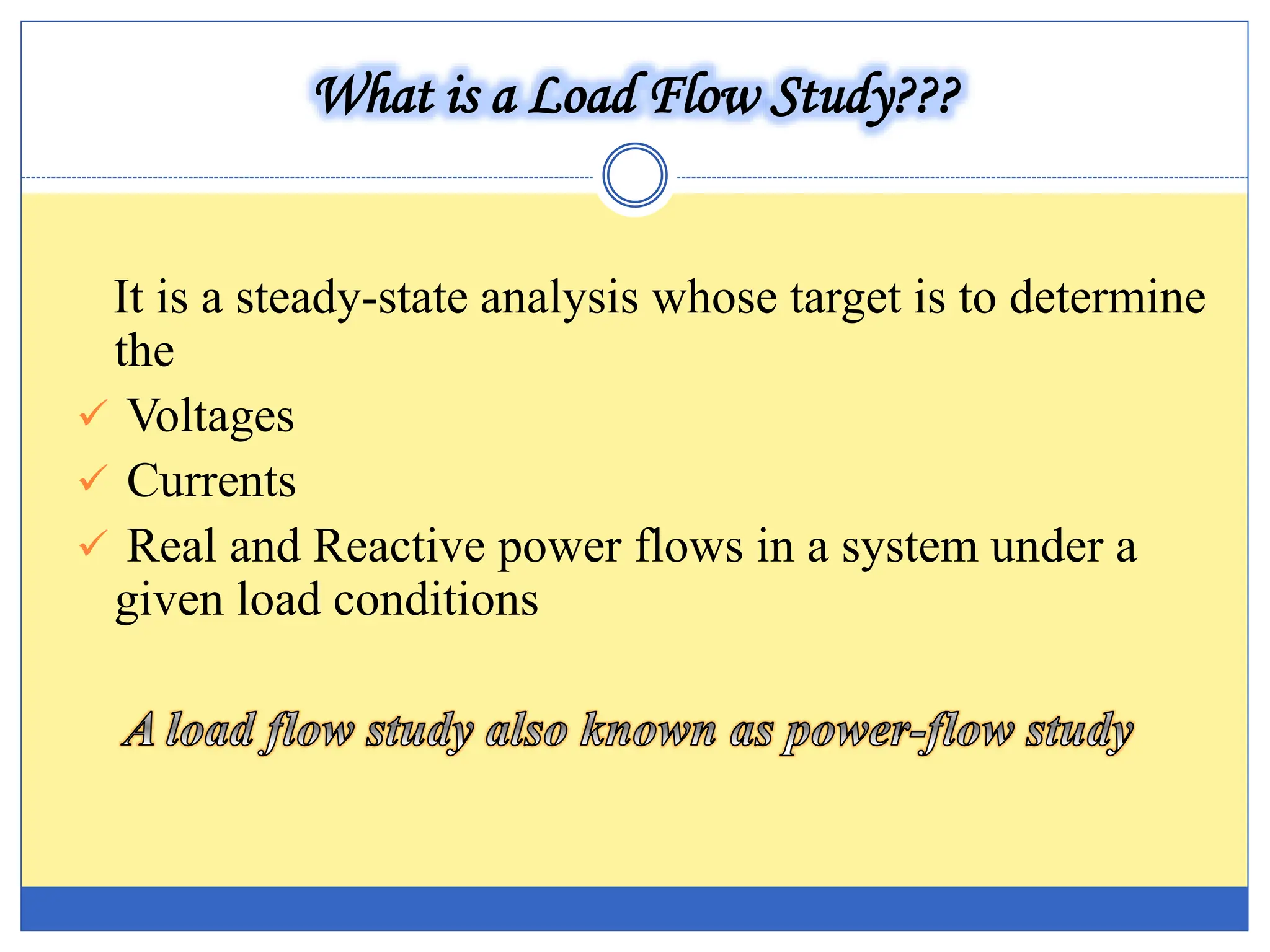


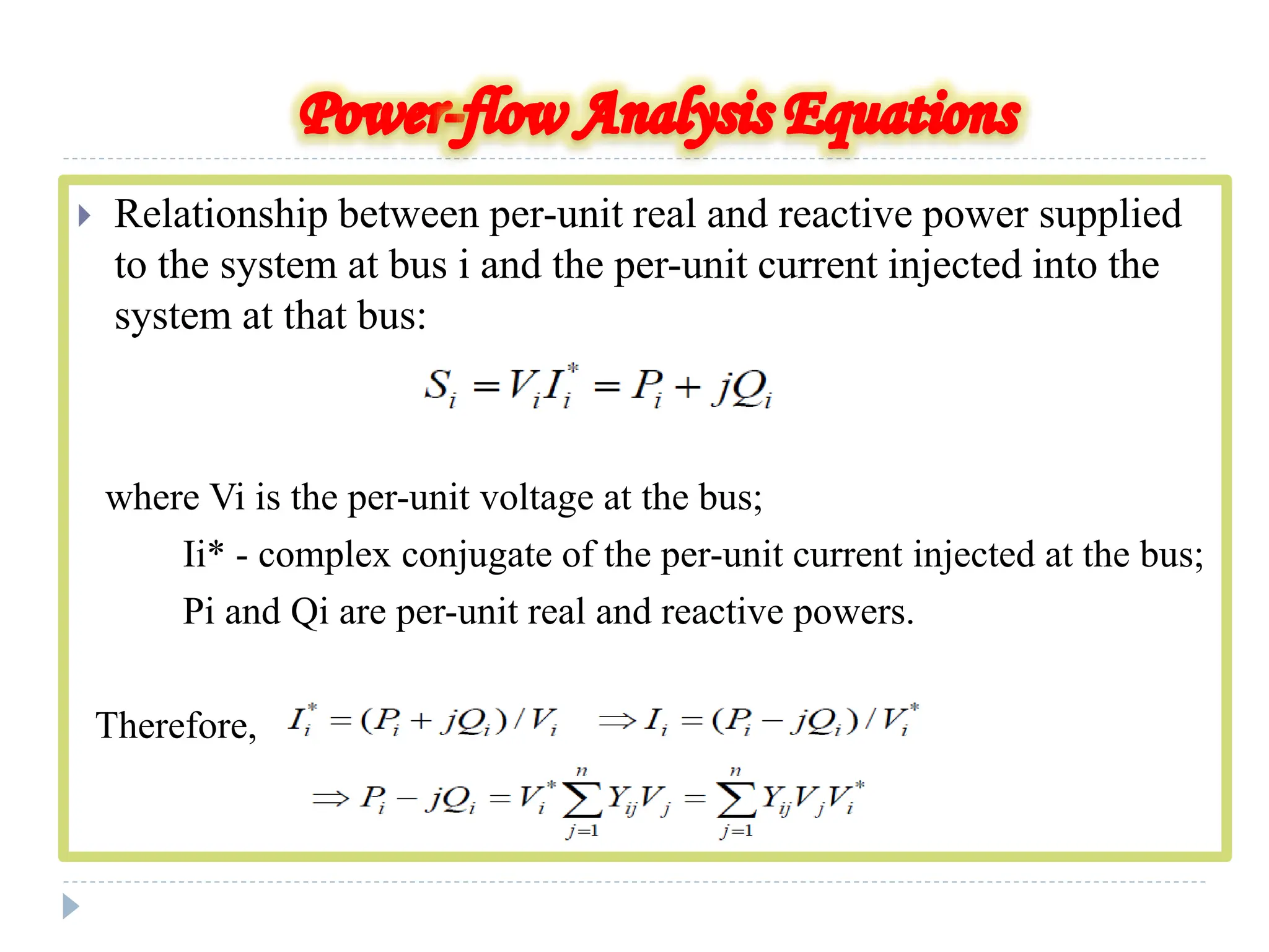
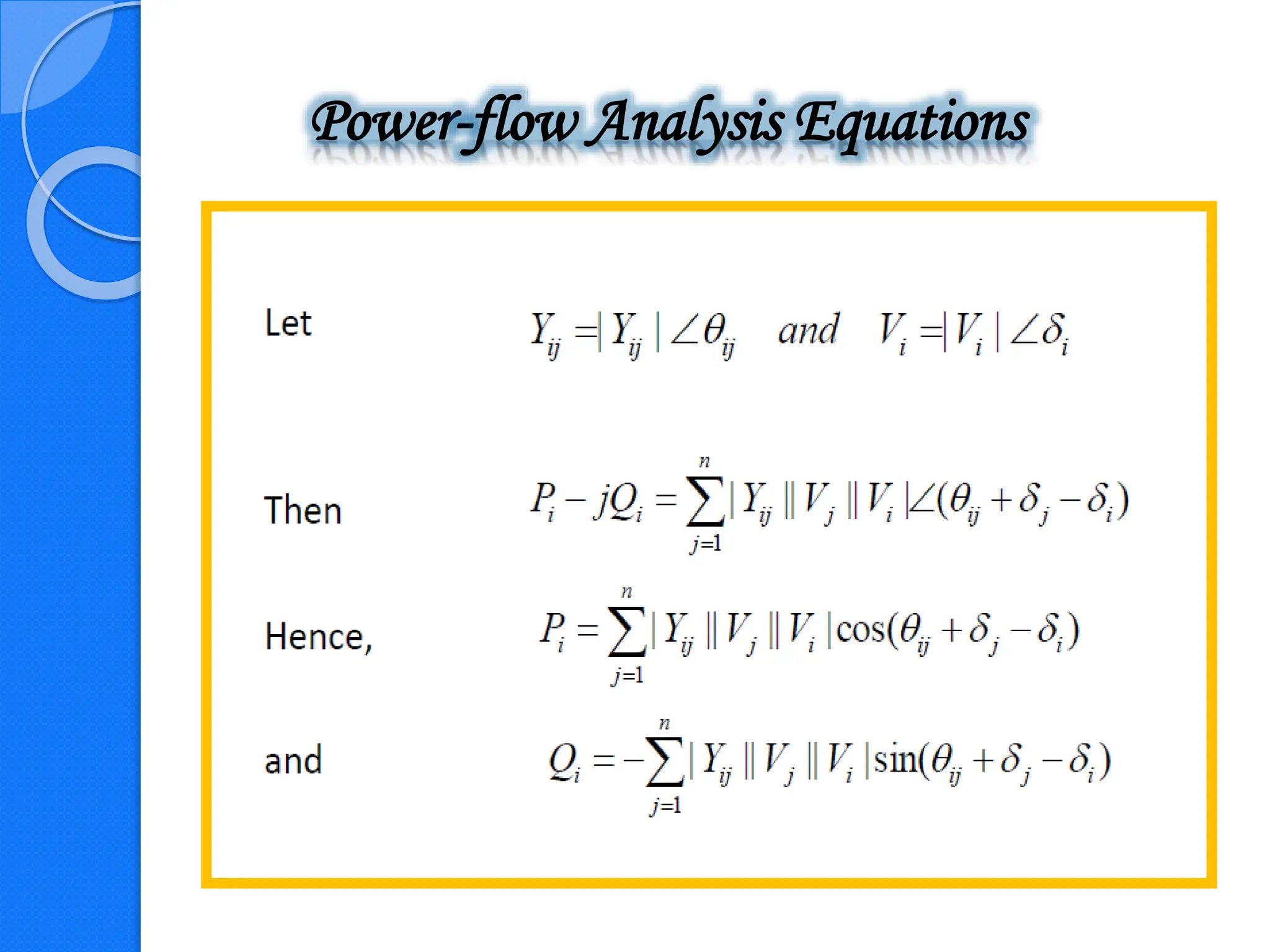


The document presents an overview of a load flow study in power systems, focusing on determining voltages, currents, and power flows under specific load conditions. It discusses the importance of such studies for ensuring generation meets demand, maintaining bus voltage levels, and preventing overloads in transmission lines. Additionally, it outlines the basic equations and classifications of buses involved in the study.


![[LEC-05] Load Flow Analysis Power System](https://cdn.slidesharecdn.com/ss_thumbnails/lec-05loadflowanalysis-241104145205-494fcb01-thumbnail.jpg?width=640&height=640&fit=bounds)


![ANPARA THERMAL POWER STATION[1] sangam.pdf](https://cdn.slidesharecdn.com/ss_thumbnails/anparathermalpowerstation1sangam-251121115219-9261cde4-thumbnail.jpg?width=640&height=640&fit=bounds)


