This document provides a summary of different types of line coding techniques used to transmit binary data, including:
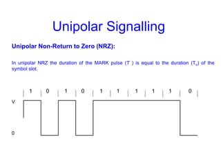
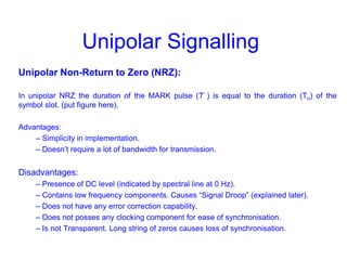
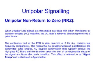
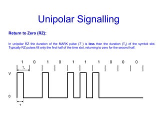
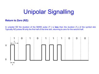
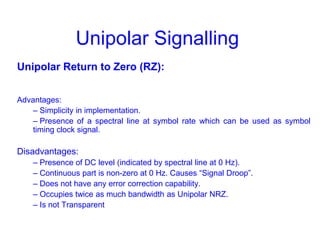
1) Unipolar signaling such as non-return to zero (NRZ) and return to zero (RZ) which have advantages of simplicity but disadvantages like presence of DC levels and signal droop.
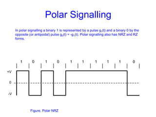
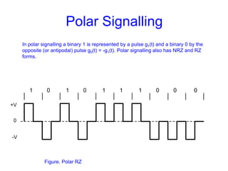
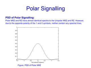
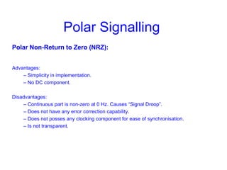
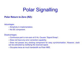
2) Polar signaling which represents 1s and 0s with opposite pulses to remove DC levels but still has signal droop issues.
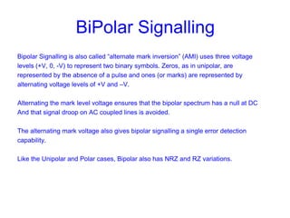
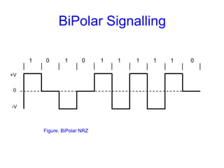
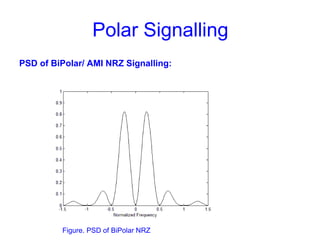
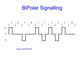
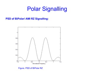
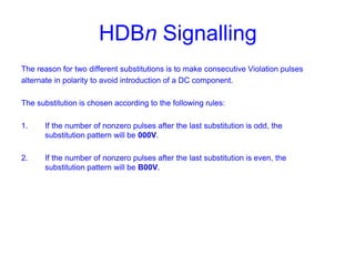
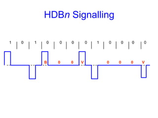
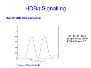
3) Bipolar/AMI signaling which uses three voltage levels and signal inversion to remove DC levels and avoid signal droop, allowing transmission over AC coupled lines.
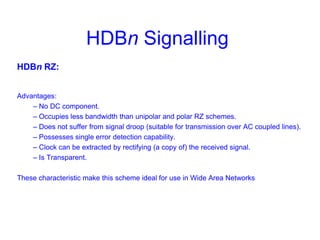
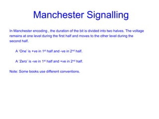
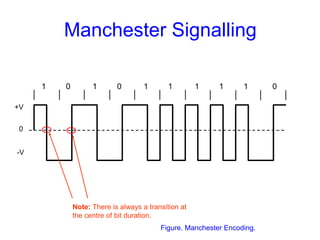
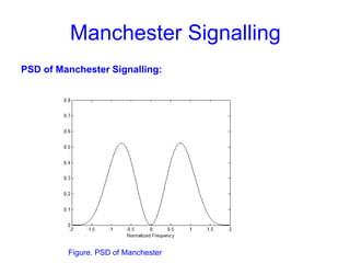
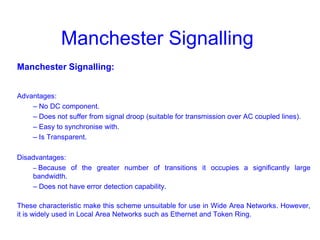
4) HDBn and Manchester coding which add transparency and clock recovery capabilities to overcome limitations