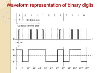
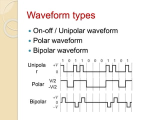
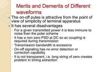
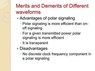
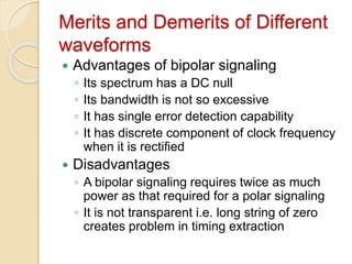
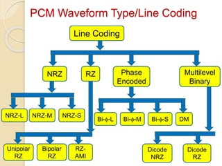
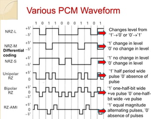
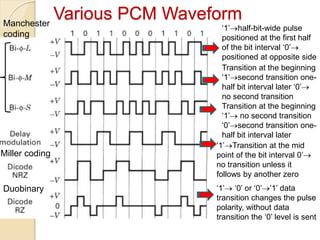
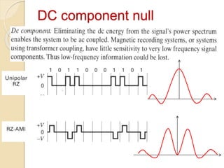
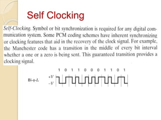
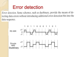
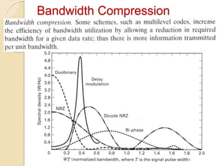
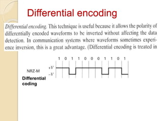
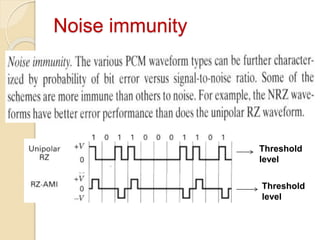
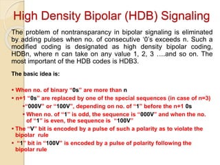
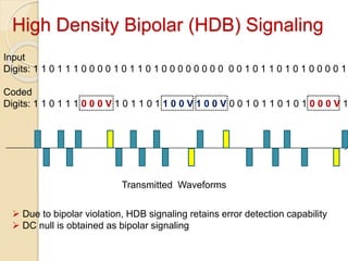
Line Coding
Contents:
Waveform representation of binary digits
PCM waveform type
 Why so many PCM waveform?
Selection of PCM waveforms
Waveform representation of binary digits
Waveform types
 On-off / Unipolar waveform
 Polar waveform
 Bipolar waveform
Polar
Bipolar
Unipola
r
V/2
-V/2
Merits and Demerits of Different
waveforms
 The on-off pulse is attractive from the point of
view of simplicity of terminal apparatus
 It has several disadvantages
◦ For a given transmitted power it is less immune to
noise than the polar scheme
◦ It has a non zero PSD at DC so ac coupling is
required during transmission
◦ Transmission bandwidth is excessive
◦ On-off signaling has no error detection or
correction capability
◦ It is not transparent, i.e. long string of zero creates
problem in timing extraction
Merits and Demerits of Different
waveforms
 Advantages of polar signaling
◦ Polar signaling is more efficient than on-
off signaling
◦ For a given transmitted power polar
signaling is more efficient
◦ It is transparent
 Disadvantages
◦ No discrete clock frequency component in
a polar signaling
Merits and Demerits of Different
waveforms
 Advantages of bipolar signaling
◦ Its spectrum has a DC null
◦ Its bandwidth is not so excessive
◦ It has single error detection capability
◦ It has discrete component of clock frequency
when it is rectified
 Disadvantages
◦ A bipolar signaling requires twice as much
power as that required for a polar signaling
◦ It is not transparent i.e. long string of zero
creates problem in timing extraction
PCM Waveform Type/Line Coding
NRZ Phase
Encoded
NRZ-L
Dicode
RZ
Dicode
NRZ
RZ Multilevel
Binary
NRZ-M NRZ-S
Unipolar
RZ
Bipolar
RZ
RZ-
AMI
Bi--L Bi--M Bi--S DM
Line Coding
Various PCM Waveform
Changes level from
‘1’’0’ or ‘0’’1’
‘1’ change in level
’0’ no change in level
Differential
coding
‘1’ no change in level
’0’ change in level
‘1’ half period wide
pulse ’0’ absence of
pulse
‘1’ one-half-bit wide
+ve pulse ’0’ one-half-
bit wide -ve pulse
‘1’ equal magnitude
alternating pulses, ’0’
absence of pulses
Various PCM Waveform
‘1’half-bit-wide pulse
positioned at the first half
of the bit interval ‘0’
positioned at opposite side
Manchester
coding
Transition at the beginning
‘1’ no second transition
‘0’second transition one-
half bit interval later
Transition at the beginning
‘1’second transition one-
half bit interval later ‘0’
no second transition
‘1’Transition at the mid
point of the bit interval 0’
no transition unless it
follows by another zero
Miller coding
‘1’ ‘0’ or ‘0’’1’ data
transition changes the pulse
polarity, without data
transition the ‘0’ level is sent
Duobinary
Why so many PCM waveform
 DC component null
 Self clocking
 Error detection
 Bandwidth Compression
 Differential encoding
 Noise immunity
DC component null
Self Clocking
Error detection
Duobinary
Bandwidth Compression
Differential encoding
Differential
coding
Noise immunity
Threshold
level
Threshold
level
High Density Bipolar (HDB) Signaling
The problem of nontransparancy in bipolar signaling is eliminated
by adding pulses when no. of consecutive ‘0’s exceeds n. Such a
modified coding is designated as high density bipolar coding,
HDBn, where n can take on any value 1, 2, 3 ….and so on. The
most important of the HDB codes is HDB3.
The basic idea is:
 When no. of binary “0s” are more than n
 n+1 “0s” are replaced by one of the special sequences (in case of n=3)
“000V” or “100V”, depending on no. of “1” before the n+1 0s
 When no. of “1” is odd, the sequence is “000V” and when the no.
of “1” is even, the sequence is “100V”
 The “V” bit is encoded by a pulse of such a polarity as to violate the
bipolar rule
 “1” bit in “100V” is encoded by a pulse of polarity following the
bipolar rule
High Density Bipolar (HDB) Signaling
Input
Digits: 1 1 0 1 1 1 0 0 0 0 1 0 1 1 0 1 0 0 0 0 0 0 0 0 0 0 1 0 1 1 0 1 0 1 0 0 0 0 1
Coded
Digits: 1 1 0 1 1 1 0 0 0 V 1 0 1 1 0 1 1 0 0 V 1 0 0 V 0 0 1 0 1 1 0 1 0 1 0 0 0 V 1
Transmitted Waveforms
 Due to bipolar violation, HDB signaling retains error detection capability
 DC null is obtained as bipolar signaling
Digital Modulation
Contents:
 Digital Modulation Techniques
 Bandwidth requirements
 Transmitter and Receiver Operations

Digital signal encoding techniques_Digital-3.pptx

  • 1.
    Line Coding Contents: Waveform representationof binary digits PCM waveform type  Why so many PCM waveform? Selection of PCM waveforms
  • 2.
  • 3.
    Waveform types  On-off/ Unipolar waveform  Polar waveform  Bipolar waveform Polar Bipolar Unipola r V/2 -V/2
  • 4.
    Merits and Demeritsof Different waveforms  The on-off pulse is attractive from the point of view of simplicity of terminal apparatus  It has several disadvantages ◦ For a given transmitted power it is less immune to noise than the polar scheme ◦ It has a non zero PSD at DC so ac coupling is required during transmission ◦ Transmission bandwidth is excessive ◦ On-off signaling has no error detection or correction capability ◦ It is not transparent, i.e. long string of zero creates problem in timing extraction
  • 5.
    Merits and Demeritsof Different waveforms  Advantages of polar signaling ◦ Polar signaling is more efficient than on- off signaling ◦ For a given transmitted power polar signaling is more efficient ◦ It is transparent  Disadvantages ◦ No discrete clock frequency component in a polar signaling
  • 6.
    Merits and Demeritsof Different waveforms  Advantages of bipolar signaling ◦ Its spectrum has a DC null ◦ Its bandwidth is not so excessive ◦ It has single error detection capability ◦ It has discrete component of clock frequency when it is rectified  Disadvantages ◦ A bipolar signaling requires twice as much power as that required for a polar signaling ◦ It is not transparent i.e. long string of zero creates problem in timing extraction
  • 7.
    PCM Waveform Type/LineCoding NRZ Phase Encoded NRZ-L Dicode RZ Dicode NRZ RZ Multilevel Binary NRZ-M NRZ-S Unipolar RZ Bipolar RZ RZ- AMI Bi--L Bi--M Bi--S DM Line Coding
  • 8.
    Various PCM Waveform Changeslevel from ‘1’’0’ or ‘0’’1’ ‘1’ change in level ’0’ no change in level Differential coding ‘1’ no change in level ’0’ change in level ‘1’ half period wide pulse ’0’ absence of pulse ‘1’ one-half-bit wide +ve pulse ’0’ one-half- bit wide -ve pulse ‘1’ equal magnitude alternating pulses, ’0’ absence of pulses
  • 9.
    Various PCM Waveform ‘1’half-bit-widepulse positioned at the first half of the bit interval ‘0’ positioned at opposite side Manchester coding Transition at the beginning ‘1’ no second transition ‘0’second transition one- half bit interval later Transition at the beginning ‘1’second transition one- half bit interval later ‘0’ no second transition ‘1’Transition at the mid point of the bit interval 0’ no transition unless it follows by another zero Miller coding ‘1’ ‘0’ or ‘0’’1’ data transition changes the pulse polarity, without data transition the ‘0’ level is sent Duobinary
  • 10.
    Why so manyPCM waveform  DC component null  Self clocking  Error detection  Bandwidth Compression  Differential encoding  Noise immunity
  • 11.
  • 12.
  • 13.
  • 14.
  • 15.
  • 16.
  • 17.
    High Density Bipolar(HDB) Signaling The problem of nontransparancy in bipolar signaling is eliminated by adding pulses when no. of consecutive ‘0’s exceeds n. Such a modified coding is designated as high density bipolar coding, HDBn, where n can take on any value 1, 2, 3 ….and so on. The most important of the HDB codes is HDB3. The basic idea is:  When no. of binary “0s” are more than n  n+1 “0s” are replaced by one of the special sequences (in case of n=3) “000V” or “100V”, depending on no. of “1” before the n+1 0s  When no. of “1” is odd, the sequence is “000V” and when the no. of “1” is even, the sequence is “100V”  The “V” bit is encoded by a pulse of such a polarity as to violate the bipolar rule  “1” bit in “100V” is encoded by a pulse of polarity following the bipolar rule
  • 18.
    High Density Bipolar(HDB) Signaling Input Digits: 1 1 0 1 1 1 0 0 0 0 1 0 1 1 0 1 0 0 0 0 0 0 0 0 0 0 1 0 1 1 0 1 0 1 0 0 0 0 1 Coded Digits: 1 1 0 1 1 1 0 0 0 V 1 0 1 1 0 1 1 0 0 V 1 0 0 V 0 0 1 0 1 1 0 1 0 1 0 0 0 V 1 Transmitted Waveforms  Due to bipolar violation, HDB signaling retains error detection capability  DC null is obtained as bipolar signaling
  • 19.
    Digital Modulation Contents:  DigitalModulation Techniques  Bandwidth requirements  Transmitter and Receiver Operations