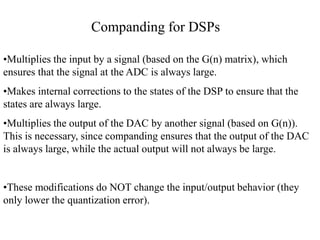
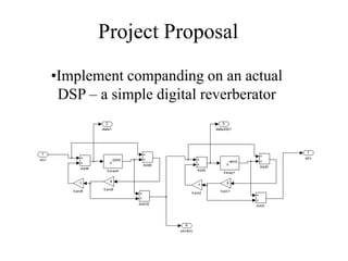
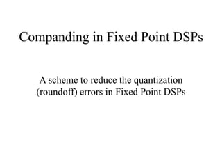
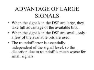
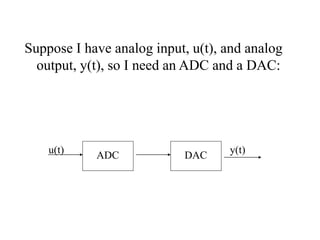
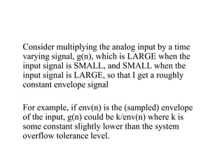
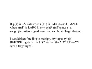
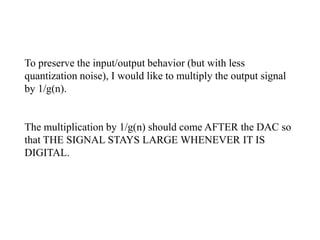
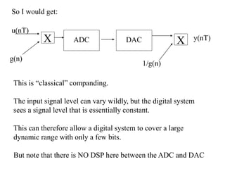
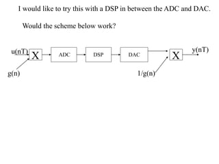
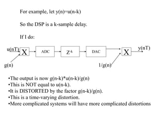
The document discusses companding, a technique to reduce quantization errors in fixed point DSPs. It involves multiplying the input signal by a time-varying gain that is large when the input is small and small when the input is large, to keep the signal level constant. Simply applying this to the input/output of a DSP will distort its behavior. Instead, the states of the DSP must be transformed to also keep them constant, while preserving the original input/output relationship. The author proposes implementing this on a digital reverberator to compare the performance of companded and non-companded versions as the bit depth varies.

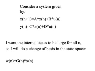
![w(n)=G(n)*x(n) so x(n)=G-1(n)*w(n)
w(n+1)=G(n+1)*x(n+1)=
G(n+1)*A*x(n)+G(n+1)*B*u(n)=
[G(n+1)*A* G-1(n)]*w(n)+[G(n+1)*B]*u(n)
y(n)=[C*G-1(n)]*w(n)+D*u(n)
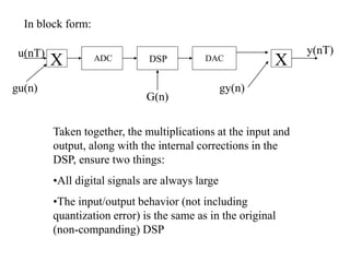
This is a new internally time-varying system,
whose states are always large, but whose
input/output behavior is identical to the original
system’s!](https://image.slidesharecdn.com/companding-240214172552-4d17f95b/85/companding-ppt-15-320.jpg)