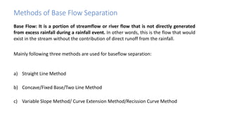
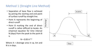
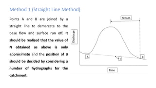
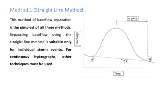
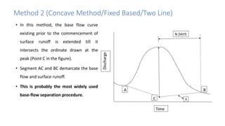
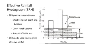
4. Methods of Base Flow Separation
Base Flow: It is a portion of streamflow or river flow that is not directly generated
from excess rainfall during a rainfall event. In other words, this is the flow that would
exist in the stream without the contribution of direct runoff from the rainfall.
Mainly following three methods are used for baseflow separation:
a) Straight Line Method
b) Concave/Fixed Base/Two Line Method
c) Variable Slope Method/ Curve Extension Method/Recission Curve Method
5. Method 1 (Straight Line Method)
• Separation of base flow is achieved
by joining the starting and end point
of surface runoff by straight line.
• Point A represents the beginning of
direct runoff
• Point B marking the end of direct
runoff is rather difficult to locate. An
empirical equation for time interval
N (days) from the peak to the point B
is
N = 0.83 A 0.2
Where A = drainage area in sq. km and
N is in days.
6. Points A and B are joined by a
straight line to demarcate to the
base flow and surface run off. It
should be realized that the value of
N obtained as above is only
approximate and the position of B
should be decided by considering a
number of hydrographs for the
catchment.
Method 1 (Straight Line Method)
7. This method of baseflow separation
is the simplest of all three methods.
Separating baseflow using the
straight-line method is suitable only
for individual storm events. For
continuous hydrographs, other
techniques must be used.
Method 1 (Straight Line Method)
8. Method 2 (Concave Method/Fixed Based/Two Line)
• In this method, the base flow curve
existing prior to the commencement of
surface runoff is extended till it
intersects the ordinate drawn at the
peak (Point C in the figure).
• Segment AC and BC demarcate the base
flow and surface runoff.
• This is probably the most widely used
base-flow separation procedure.
9. • The logic behind this method is that
when the stage in the stream rises
rapidly, there is flow from the stream
into the bank, hence baseflow should
decrease until the stages in the stream
begin to fall.
• When the stage in the stream recedes
the bank storage returns to the stream
making the baseflow contribution large.
Method 2 (Concave Method/Fixed Based/Two Line)
10. Method 3 (Recession Curve Method)
• In this method, the base flow
recession curve after the
depletion of the flood water is
extended backward till it
intersects the ordinate at the
point of inflection Pi (BD).
• Points A and D are joined by an
arbitrary smooth curve.
11. • This method of base flow is realistic
in situations where the
groundwater contributions are
significant and reach the stream
quickly.
• This method is preferred where the
stream and groundwater table are
hydraulically connected and flow
from groundwater storage reaches
the stream fairly rapidly.
Method 3 (Recession Curve Method)
12. Methods of Base Flow Separation
➢ It is seen that all three methods of
baseflow separation are rather
arbitrary.
➢ The selection of any one of them
depends upon the local practice and
successful predictions achieved in the
past.
➢ The surface run-off hydrograph
obtained after base-flow separation
is also known as Direct Runoff
Hydrograph (DRH).
13. Effective Rainfall
Hyetograph (ERH)
• Effective rainfall (Also known
as Excess Rainfall) – Part of
precipitation that entirely
contribute to the formation
of direct runoff
• ERH shows effective rainfall
and initial loss
14. Effective Rainfall
Hyetograph (ERH)
• ERH provide information on
– Effective rainfall depth and
duration
– Direct runoff volume
– Amount of initial loss
• ERH can be used to determine
effective rainfall
15. Effective Rainfall Hyetograph (ERH)
➢ It is thus the total rainfall in a given duration from which infiltration and initial losses
are subtracted
➢ As such, ER could be defined as that rainfall that is neither retained on the land
surface nor infiltrated into the soil.
➢ The resulting hyetograph is known as Effective Rainfall Hyetograph (ERH) or Excess
Rainfall Hyetograph
𝐸𝑅 =
𝑖=1
𝑛
𝐼𝑖Δ𝑡
ER – effective rainfall depth (cm or mm), 𝐼𝑖 = Rainfall intensity at time i (cm/h or mm/h),
Δt = time interval
16. Direct Runoff Hydrograph (DRH)
➢ Plot of direct runoff and time
➢ Area of hydrograph gives the volume of direct runoff which is response to effective
rainfall
➢ No base flow included to direct runoff hydrograph
Relationship between DRH and ERH
• ERH is usually in cm/h plotted against time.
• The area of ERH multiplied by the catchment area gives the total volume of direct
run off which is the same as the area of DRH.
Volume of runoff = ER x A (Unit conversion needs to be done)
Initial Loss = Area of hyetograph – Area of ERH
17. Unit Hydrograph
➢ Hydrograph of surface runoff of a catchment resulting from unit depth (usually 1 cm) of rainfall
excess (effective rainfall) occurring uniformly over the watershed and at uniform rate for a
specified duration.
➢ Assumptions in deriving Unit Hydrograph
– Uniform intensity of rainfall within a specified duration
– Effective rainfall is uniformly distributed in the watershed
– Base of time duration of the direct runoff hydrograph is constant
– Direct runoff due to effective rainfall over the watershed is always same, not vary with
time
– Relationship between direct runoff and effective rainfall is linear (Example: if ER of x cm
generate y m3 of direct runoff, 3x will generate 3y m3)
18. Use and Applications of Unit Hydrograph
➢The unit hydrographs are used in many hydrological problems such as:
• In the development of flood hydrographs corresponding to design storms
that are required for the design of hydraulic structures.
• In the watershed simulation models
• In the studies of flood forecasting and flood warning systems.
• In extending the flood flow records, based on rainfall records.