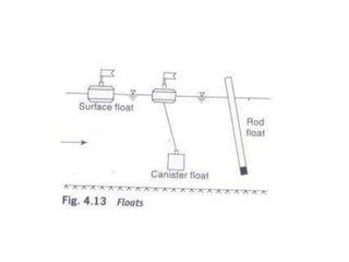
Stream Flow Measurement
Dr. Kiran Yarrakula
Associate Professor, CDMM
VIT, Vellore
STREAMFLOW MEASUREMENT
• Stream flow representing the runoff phase of
the hydrologic cycle is the most important
basic data for hydrologic studies.
• It was seen in the previous chapters that
precipitation, evaporation and evapo-
transpiration are all difficult to measure
exactly and the presently adopted methods
have severe limitations.
• In contrast, the measurement of stream flow is
amenable to fairly accurate assessment.
• Interestingly, stream flow is the only part of the
hydrologic cycle that can be measured accurately.
• A stream can be defined as a flow channel into
which the surface runoff from a specified basin
drains. Generally, there is considerable exchange
of water between a stream and the underground
water.
• Stream flow is measured in units of discharge
(m3/s) occurring at a specified time and
constitutes historical data. The measurement
of discharge in a stream forms an important
branch of Hydrometry, the science and
practice of water measurement.
Measurement techniques
• Stream flow measurement techniques can be broadly
classified into two categories as
(i) direct determination
– (a) Area-velocity methods
– (b) Dilution techniques,
– (c) Electromagnetic method, and
– (d) Ultrasonic method.
(ii) indirect determination
- (a) Hydraulic, structures, such as weirs, flumes and
gated structures, and
-(b) Slope-area method.
4.3 Measurement of Velocity
• The measurement of velocity is an important
aspect of many direct stream-flow measurement
techniques.
• A mechanical device, called current meter,
consisting essentially of a rotating element is
probably the most commonly used instrument for
accurate determination of the stream-velocity
field.
• Approximate stream velocities can be determined
by floats.
4.3.1 Current Meters
• The most commonly used instrument in hydrometry
to measure the velocity at a point in the flow cross-
section is the current meter.
• It consists essentially of a rotating element which
rotates due to the reaction of the stream current
with an angular velocity proportional to the stream
velocity.
• Historically, Robert Hooke (1663) invented a
propeller-type current meter to measure the
distance traversed by a ship.
• The present day cup-type instrument and the
electrical make-and-break mechanism were
invented by Henry in 1868. There are two
main types of current meters.
1. Vertical-axis meters, and
2. Horizontal-axis meters.
1. Vertical-Axis Meters
• These instruments consist of a series of conical cups
mounted around a vertical axis. The cups rotate in a horizontal
plane and a earn attached to the vertical axial spindle records
generated signals proportional to the revolutions of the cup
assembly.
• The Price current meter and Gurley current meter are
typical instruments under this category. The normal range of
velocities is from 0.15 to 4.0 m/s. The accuracy of these
instruments is about 1.50% at the threshold value and
improves to about 0.30% at speeds in excess of 1.0 mls.
• Vertical-axis instruments have the disadvantage that
they cannot be used in situations where there are appreciable
vertical components of velocities. For example, the
instrument shows positive
velocity when it is lifted vertically in still water.
2. Horizontal-Axis Meters
• These meters consist of a propeller mounted at the
end of horizontal shaft. These come in a wide variety
of size with propeller diameters in the range 6 to 12
cm, and can register velocities in the range of 0.15 to
4.0 m/s. Ott, Neyrtec and Watt-type meters are typical
instruments under this kind.
• These meters are fairly rugged and are not affected by
oblique flows of as much as 15°. The accuracy of the
instrument is about I% at the threshold value and is
about 0.25% at a velocity of 0.3 mls and above.
• The instruments have a provision to count. the number
of revolutions is a known interval of time. This is
usually accomplished by the making and breaking of an
electric circuit, either mechanically or
electromagnetically at each revolution of the shaft.
• In older model instruments the breaking of the circuit
would be counted through an audible sharp signal
("tick") heard on a headphone.
• The revolutions per second is calculated by counting
the number of such signals in a known interval of time,
usually about 100 s. Present-day models employ
electromagnetic counters with digital signal processing
capabilities.
4.3.2 Velocity Measurement by Floats
• A floating object on the surface of a stream when
timed can yield the surface velocity by the
relation.
• where S = distance travelled in time t.
• This method of measuring velocities while
primitive still finds applications in special
circumstances, such as (i) a small stream in flood,
(ii) small stream with a rapidly changing water
surface, and (iii) preliminary or exploratory
surveys.
• While any floating object can be used, normally
specially made leak proof and easily identifiable floats
are used.
• A simple float moving on the stream surface is called a
surface float. It is easy to use and the mean velocity is
obtained by multiplying the observed surface velocity
by a reduction coefficient .
• However, surface floats are affected by surface winds.
To get the average velocity in the vertical directly,
special floats in which part of the body is underwater
are used. Rod float (Fig. 4.13), in which a cylindrical rod
is weighed so that it can float vertically, belongs to this
category.
Stream flow  measurement

Stream flow measurement

  • 1.
    Stream Flow Measurement Dr.Kiran Yarrakula Associate Professor, CDMM VIT, Vellore
  • 2.
    STREAMFLOW MEASUREMENT • Streamflow representing the runoff phase of the hydrologic cycle is the most important basic data for hydrologic studies. • It was seen in the previous chapters that precipitation, evaporation and evapo- transpiration are all difficult to measure exactly and the presently adopted methods have severe limitations.
  • 3.
    • In contrast,the measurement of stream flow is amenable to fairly accurate assessment. • Interestingly, stream flow is the only part of the hydrologic cycle that can be measured accurately. • A stream can be defined as a flow channel into which the surface runoff from a specified basin drains. Generally, there is considerable exchange of water between a stream and the underground water.
  • 4.
    • Stream flowis measured in units of discharge (m3/s) occurring at a specified time and constitutes historical data. The measurement of discharge in a stream forms an important branch of Hydrometry, the science and practice of water measurement.
  • 5.
    Measurement techniques • Streamflow measurement techniques can be broadly classified into two categories as (i) direct determination – (a) Area-velocity methods – (b) Dilution techniques, – (c) Electromagnetic method, and – (d) Ultrasonic method. (ii) indirect determination - (a) Hydraulic, structures, such as weirs, flumes and gated structures, and -(b) Slope-area method.
  • 6.
    4.3 Measurement ofVelocity • The measurement of velocity is an important aspect of many direct stream-flow measurement techniques. • A mechanical device, called current meter, consisting essentially of a rotating element is probably the most commonly used instrument for accurate determination of the stream-velocity field. • Approximate stream velocities can be determined by floats.
  • 7.
    4.3.1 Current Meters •The most commonly used instrument in hydrometry to measure the velocity at a point in the flow cross- section is the current meter. • It consists essentially of a rotating element which rotates due to the reaction of the stream current with an angular velocity proportional to the stream velocity. • Historically, Robert Hooke (1663) invented a propeller-type current meter to measure the distance traversed by a ship.
  • 8.
    • The presentday cup-type instrument and the electrical make-and-break mechanism were invented by Henry in 1868. There are two main types of current meters. 1. Vertical-axis meters, and 2. Horizontal-axis meters.
  • 9.
    1. Vertical-Axis Meters •These instruments consist of a series of conical cups mounted around a vertical axis. The cups rotate in a horizontal plane and a earn attached to the vertical axial spindle records generated signals proportional to the revolutions of the cup assembly. • The Price current meter and Gurley current meter are typical instruments under this category. The normal range of velocities is from 0.15 to 4.0 m/s. The accuracy of these instruments is about 1.50% at the threshold value and improves to about 0.30% at speeds in excess of 1.0 mls. • Vertical-axis instruments have the disadvantage that they cannot be used in situations where there are appreciable vertical components of velocities. For example, the instrument shows positive velocity when it is lifted vertically in still water.
  • 11.
    2. Horizontal-Axis Meters •These meters consist of a propeller mounted at the end of horizontal shaft. These come in a wide variety of size with propeller diameters in the range 6 to 12 cm, and can register velocities in the range of 0.15 to 4.0 m/s. Ott, Neyrtec and Watt-type meters are typical instruments under this kind. • These meters are fairly rugged and are not affected by oblique flows of as much as 15°. The accuracy of the instrument is about I% at the threshold value and is about 0.25% at a velocity of 0.3 mls and above.
  • 12.
    • The instrumentshave a provision to count. the number of revolutions is a known interval of time. This is usually accomplished by the making and breaking of an electric circuit, either mechanically or electromagnetically at each revolution of the shaft. • In older model instruments the breaking of the circuit would be counted through an audible sharp signal ("tick") heard on a headphone. • The revolutions per second is calculated by counting the number of such signals in a known interval of time, usually about 100 s. Present-day models employ electromagnetic counters with digital signal processing capabilities.
  • 14.
    4.3.2 Velocity Measurementby Floats • A floating object on the surface of a stream when timed can yield the surface velocity by the relation. • where S = distance travelled in time t. • This method of measuring velocities while primitive still finds applications in special circumstances, such as (i) a small stream in flood, (ii) small stream with a rapidly changing water surface, and (iii) preliminary or exploratory surveys.
  • 15.
    • While anyfloating object can be used, normally specially made leak proof and easily identifiable floats are used. • A simple float moving on the stream surface is called a surface float. It is easy to use and the mean velocity is obtained by multiplying the observed surface velocity by a reduction coefficient . • However, surface floats are affected by surface winds. To get the average velocity in the vertical directly, special floats in which part of the body is underwater are used. Rod float (Fig. 4.13), in which a cylindrical rod is weighed so that it can float vertically, belongs to this category.