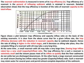
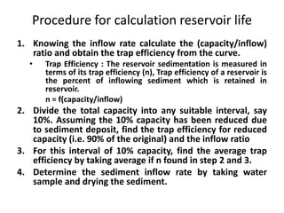
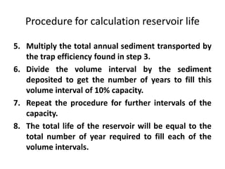
This document discusses reservoir sedimentation and provides information on factors that influence sedimentation rates. It describes the stages of sediment transport and deposition in reservoirs. Key points include:
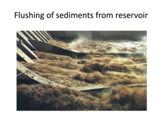
1. Sedimentation is a difficult problem for dams as it reduces storage capacity over time. Dead storage is provided to accommodate deposits.
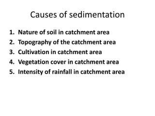
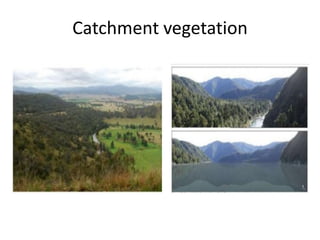
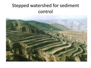
2. Factors like soil type, topography, vegetation cover and rainfall intensity affect the sediment load carried by rivers. Steeper slopes with less vegetation result in higher sediment loads.
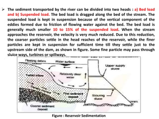
3. Sediment consists of bed load and suspended load. Coarser particles settle near the reservoir inlet while finer particles settle farther upstream, near the dam.
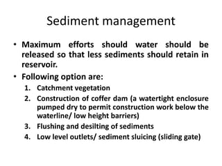
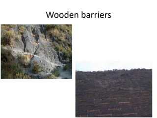
4. Management options to reduce sedimentation include catch


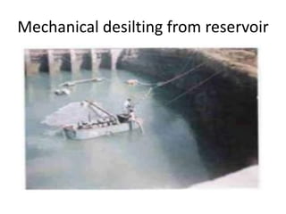
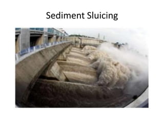


![presentation m.tech nithamirpurmce421[1].pptx](https://cdn.slidesharecdn.com/ss_thumbnails/shivani22mce4211-250603162358-f833ca66-thumbnail.jpg?width=640&height=640&fit=bounds)


