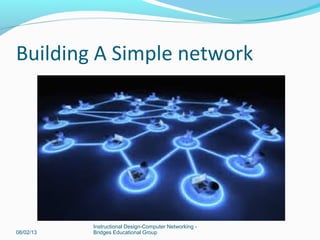
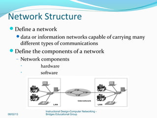
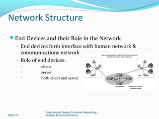
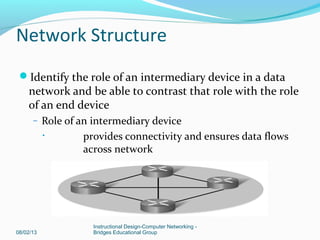
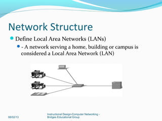
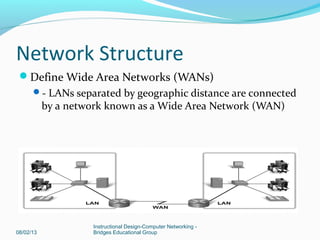
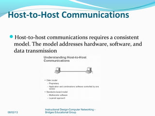
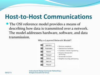
© 2006 Cisco Systems, Inc. All rights reserved. Cisco Public 1
www.professordkinney.com
Building A Simple network
08/02/13
Instructional Design-Computer Networking -
Bridges Educational Group
Objectives
 Describe how networking works
 Host-to-host communication
 Introducing LANs
 Understanding Ethernet and Switch
08/02/13
Instructional Design-Computer Networking -
Bridges Educational Group
Network Structure
Define a network
data or information networks capable of carrying many
different types of communications
Define the components of a network
– Network components
• hardware
• software
08/02/13
Instructional Design-Computer Networking -
Bridges Educational Group
Network Structure
End Devices and their Role in the Network
– End devices form interface with human network &
communications network
– Role of end devices:
• client
• server
• both client and server
08/02/13
Instructional Design-Computer Networking -
Bridges Educational Group
Network Structure
Identify the role of an intermediary device in a data
network and be able to contrast that role with the role
of an end device
– Role of an intermediary device
• provides connectivity and ensures data flows
across network
08/02/13
Instructional Design-Computer Networking -
Bridges Educational Group
Network Structure
08/02/13
Instructional Design-Computer Networking -
Bridges Educational Group
Define Local Area Networks (LANs)
- A network serving a home, building or campus is
considered a Local Area Network (LAN)
Network Structure
08/02/13
Instructional Design-Computer Networking -
Bridges Educational Group
Define Wide Area Networks (WANs)
- LANs separated by geographic distance are connected
by a network known as a Wide Area Network (WAN)
Host-to-Host Communications
Host-to-host communications requires a consistent
model. The model addresses hardware, software, and
data transmission
08/02/13
Instructional Design-Computer Networking -
Bridges Educational Group
Host-to-Host Communications
The OSI reference model provides a means of
describing how data is transmitted over a network.
The model addresses hardware, software, and data
transmission.
08/02/13
Instructional Design-Computer Networking -
Bridges Educational Group
Host-to-Host Communications
Peer-to-Peer Communication
So that data packets can travel from the source to the
destination, each layer of the OSI model at the source must
communicate with its peer layer at the destination. This topic
describes the process of peer-to-peer communication.
During the process of peer-to-peer communication, the
protocols at each layer exchange packets of information called
protocol data units (PDUs) between peer layers.
These data packets originate at a source on a network and then
travel to a destination. Each layer depends on the OSI layer
below it to provide a service. To perform its service function, the
lower layer uses encapsulation to put the protocol data unit
(PDU) from the upper layer into lower layer data field. Each
layer then adds whatever headers the layer needs to perform its
function. As the data moves down from Layer 7 through Layer 2
of the OSI model, additional headers are added.
08/02/13
Instructional Design-Computer Networking -
Bridges Educational Group
Host-to-Host Communications
The network layer provides a service to the transport layer,
and the transport layer presents data to the network
subsystem. The network layer moves the data through the
Internet by encapsulating the data and attaching a header
to create a packet (the Layer 3 PDU). The header contains
information required to complete the transfer, such as
source and destination logical addresses.
The data link layer provides a service to the network layer
by encapsulating the network layer packet in a frame (the
Layer 2 PDU). The frame header contains the physical
addresses required to complete the data link functions,
and the frame trailer contains the FCS.
The physical layer provides a service to the data link layer,
encoding the data-link frame into a pattern of 1s and 0s
(bits) for transmission on the medium (usually a wire) at
Layer 1.
08/02/13
Instructional Design-Computer Networking -
Bridges Educational Group
Host-to-Host Communications
08/02/13
Instructional Design-Computer Networking -
Bridges Educational Group
Ethernet
08/02/13
Instructional Design-Computer Networking -
Bridges Educational Group
OSI model layers 1 (physical) and 2 (data link)
TCP/IP model Network Access layer
Application
Presentation
Session
Transport
Network
Data link
Physical
Ethernet
Application
Transport
Internet
Network Access
Ethernet
The most common LAN technology
Different media (copper cable, optical fibre)
Different bandwidths (10, 100Mbps, Gbps, +)
Same addressing scheme
Same basic frame format
08/02/13
Instructional Design-Computer Networking -
Bridges Educational Group
Ethernet history
First LAN was Ethernet, designed at Xerox
1980 Ethernet standard published by DIX (Digital, Intel, Xerox)
1985 IEEE modified Ethernet standard and published as 802.3
Ethernet802.3
802.2MAC
LLC
Advantages of Ethernet
Simplicity and ease of maintenance
Ability to incorporate new technologies (e.g. fibre
optic, higher bandwidths)
Reliability
Low cost of installation and upgrade
08/02/13
Instructional Design-Computer Networking -
Bridges Educational Group
Ethernet Frame
Packet
Packet TrailerFrame header
Packet from
Network layer is
encapsulated
Preamble Destination
address
Start of
frame
delimiter
Source
address
Length
/type
7 1 6 6 2
Packet
Data
Frame
Check
Seq.
46-1500 4
Field size in bytes. Preamble and SFD are not counted in
frame size. Frame is 64-1518 (later 1522) bytes.
08/02/13
Instructional Design-Computer Networking -
Bridges Educational Group
Hub and Switch
Shared medium
Shared bandwidth
Collisions
Point to point links
Dedicated bandwidth
Use full duplex – no collisions
Hub
Switch
08/02/13
Instructional Design-Computer Networking -
Bridges Educational Group
Switching table
Switch builds a switching table
matching its port numbers to the
MAC addresses of devices connected
to them.
When a frame arrives, it reads the
destination MAC address, looks it
up in the table, finds the right port
and forwards the frame.
08/02/13
Instructional Design-Computer Networking -
Bridges Educational Group
Flooding
If the switch does not find the destination address in
its table then it floods the frame through all ports
except the incoming port.
Broadcast messages are flooded.
08/02/13
Instructional Design-Computer Networking -
Bridges Educational Group
Learning addresses
The switch learns addresses by looking at the source
MAC address of an incoming frame.
It then matches the address to the port where the
frame came in and puts the information in its table.
Entries are time stamped and removed from the table
when the time runs out.
They can be refreshed when another frame comes in
from the same host.
08/02/13
Instructional Design-Computer Networking -
Bridges Educational Group
ARP table
A host wants to send a message.
It knows the destination IP address and puts it in the
packet header.
It looks in its ARP table and finds the corresponding
MAC address.
It puts the MAC address in the frame header.
08/02/13
Instructional Design-Computer Networking -
Bridges Educational Group
Internetwork Operating System
Most Cisco devices use the Cisco IOS.
Details vary with the device and feature set.
Normal access through a command line.
Stored in flash memory and can be upgraded.
Usually copied into RAM when the device is powered
on, and run from RAM.
Router prompts
User EXEC mode
Privileged EXEC mode
Global Configuration mode
Specific Configuration modes
Router>
Router#
Router(config)#
Router(config-if)#
and others
EXEC modes
You log in to User EXEC mode
Router>
You can give basic monitoring commands but cannot
change the configuration
Enter enable to go to Privileged EXEC mode
Router#
Password may be used for security
You can give more commands and can go to
configuration modes
Configuration modes
Start in privileged EXEC mode and enter the
configure terminal (config t) command
Router# config t
Router(config)#
The prompt changes
This is global configuration mode
Additional commands take you to interface
configuration, router configuration etc.
Console password
Paris(config)#line con 0
Paris(config-line)#password cisco
Paris(config-line)#login
Paris(config-line)#exit
Restricts access via the console
Use cisco as the password in labs.
Use a proper strong password on production
networks
Vty password for Telnet
Paris(config)#line vty 0 4
Paris(config-line)#password cisco
Paris(config-line)#login
Paris(config-line)#exit
Allows and restricts access via 5 vty lines
Use cisco as the password in labs.
Use a proper strong, different password on
production networks
Enable and enable secret
Paris(config)#enable secret class
The password class is needed when you type enable
to enter privileged exec mode
This password is encrypted
Paris(config)#enable password cisco
Not encrypted, used on older routers
If you configure both, then only the enable secret is
used.
Back up to TFTP server
Start TFTP server software on host
Paris#copy running-config tftp
Remote host []? 172.16.1.1
Name of configuration file to write [Paris-config]?
Paris12Oct07
Write file Paris12Oct07 to 172.16.1.1? [confirm] y
Writing Paris12Oct07 ! ! ! ! ! ! [OK]
Erase startup configuration
Paris#erase NVRAM:startup-config
Paris#erase startup-config
Paris#erase start
If you reload, then the router starts up with the
default configuration. No passwords, no IP addresses
etc.
Caution if you get this command wrong then you
could erase something else, e.g. IOS
Restore file from TFTP server
Router#copy tftp running-config
You will be prompted for IP address and file name.
Configuration is copied into RAM and takes effect at
once.
Save to NVRAM.
Configure a router interface
Paris(config)#interface FastEthernet 0/0
Paris(config-if)#ip address 172.16.1.1 255.255.0.0
Paris(config-if)#no shutdown
Paris(config-if)#exit
Interface names vary, depending on whether the
router is modular and on the bandwidth.
E.g. interface Ethernet 0 on an older router
Configure a router interface
Paris(config)#interface serial 0/0
Paris(config-if)#ip address 192.168.4.1 255.255.255.0
(Paris(config-if)#clock rate 64000)
Paris(config-if)#no shutdown
Paris(config-if)#exit DCE only
Switch IP address
The switch IP address goes on a virtual interface, not
a real one, normally VLAN1.
SwA(config)#interface VLAN1
SwA(config-if)#ip address 172.16.255.1 255.255.0.0
SwA(config-if)#no shutdown
SwA(config-if)#exit
Interface – show commands
show interfaces states whether up or down, gives
some protocol information and statistics about
interface use.
show ip interface gives IP addresses and much
more.
show ip interface brief gives summary of IP
addresses and whether up/down. Very useful
command.
Summary
Network communications using peer to peer hos
communication example.
Explains how LAN works .
Ethernet and switch how it works.
Cisco IOS commands.
08/02/13
Instructional Design-Computer Networking -
Bridges Educational Group

Lesson 1 slideshow

  • 1.
    © 2006 CiscoSystems, Inc. All rights reserved. Cisco Public 1 www.professordkinney.com
  • 2.
    Building A Simplenetwork 08/02/13 Instructional Design-Computer Networking - Bridges Educational Group
  • 3.
    Objectives  Describe hownetworking works  Host-to-host communication  Introducing LANs  Understanding Ethernet and Switch 08/02/13 Instructional Design-Computer Networking - Bridges Educational Group
  • 4.
    Network Structure Define anetwork data or information networks capable of carrying many different types of communications Define the components of a network – Network components • hardware • software 08/02/13 Instructional Design-Computer Networking - Bridges Educational Group
  • 5.
    Network Structure End Devicesand their Role in the Network – End devices form interface with human network & communications network – Role of end devices: • client • server • both client and server 08/02/13 Instructional Design-Computer Networking - Bridges Educational Group
  • 6.
    Network Structure Identify therole of an intermediary device in a data network and be able to contrast that role with the role of an end device – Role of an intermediary device • provides connectivity and ensures data flows across network 08/02/13 Instructional Design-Computer Networking - Bridges Educational Group
  • 7.
    Network Structure 08/02/13 Instructional Design-ComputerNetworking - Bridges Educational Group Define Local Area Networks (LANs) - A network serving a home, building or campus is considered a Local Area Network (LAN)
  • 8.
    Network Structure 08/02/13 Instructional Design-ComputerNetworking - Bridges Educational Group Define Wide Area Networks (WANs) - LANs separated by geographic distance are connected by a network known as a Wide Area Network (WAN)
  • 9.
    Host-to-Host Communications Host-to-host communicationsrequires a consistent model. The model addresses hardware, software, and data transmission 08/02/13 Instructional Design-Computer Networking - Bridges Educational Group
  • 10.
    Host-to-Host Communications The OSIreference model provides a means of describing how data is transmitted over a network. The model addresses hardware, software, and data transmission. 08/02/13 Instructional Design-Computer Networking - Bridges Educational Group
  • 11.
    Host-to-Host Communications Peer-to-Peer Communication Sothat data packets can travel from the source to the destination, each layer of the OSI model at the source must communicate with its peer layer at the destination. This topic describes the process of peer-to-peer communication. During the process of peer-to-peer communication, the protocols at each layer exchange packets of information called protocol data units (PDUs) between peer layers. These data packets originate at a source on a network and then travel to a destination. Each layer depends on the OSI layer below it to provide a service. To perform its service function, the lower layer uses encapsulation to put the protocol data unit (PDU) from the upper layer into lower layer data field. Each layer then adds whatever headers the layer needs to perform its function. As the data moves down from Layer 7 through Layer 2 of the OSI model, additional headers are added. 08/02/13 Instructional Design-Computer Networking - Bridges Educational Group
  • 12.
    Host-to-Host Communications The networklayer provides a service to the transport layer, and the transport layer presents data to the network subsystem. The network layer moves the data through the Internet by encapsulating the data and attaching a header to create a packet (the Layer 3 PDU). The header contains information required to complete the transfer, such as source and destination logical addresses. The data link layer provides a service to the network layer by encapsulating the network layer packet in a frame (the Layer 2 PDU). The frame header contains the physical addresses required to complete the data link functions, and the frame trailer contains the FCS. The physical layer provides a service to the data link layer, encoding the data-link frame into a pattern of 1s and 0s (bits) for transmission on the medium (usually a wire) at Layer 1. 08/02/13 Instructional Design-Computer Networking - Bridges Educational Group
  • 13.
  • 14.
    Ethernet 08/02/13 Instructional Design-Computer Networking- Bridges Educational Group OSI model layers 1 (physical) and 2 (data link) TCP/IP model Network Access layer Application Presentation Session Transport Network Data link Physical Ethernet Application Transport Internet Network Access
  • 15.
    Ethernet The most commonLAN technology Different media (copper cable, optical fibre) Different bandwidths (10, 100Mbps, Gbps, +) Same addressing scheme Same basic frame format 08/02/13 Instructional Design-Computer Networking - Bridges Educational Group
  • 16.
    Ethernet history First LANwas Ethernet, designed at Xerox 1980 Ethernet standard published by DIX (Digital, Intel, Xerox) 1985 IEEE modified Ethernet standard and published as 802.3 Ethernet802.3 802.2MAC LLC
  • 17.
    Advantages of Ethernet Simplicityand ease of maintenance Ability to incorporate new technologies (e.g. fibre optic, higher bandwidths) Reliability Low cost of installation and upgrade 08/02/13 Instructional Design-Computer Networking - Bridges Educational Group
  • 18.
    Ethernet Frame Packet Packet TrailerFrameheader Packet from Network layer is encapsulated Preamble Destination address Start of frame delimiter Source address Length /type 7 1 6 6 2 Packet Data Frame Check Seq. 46-1500 4 Field size in bytes. Preamble and SFD are not counted in frame size. Frame is 64-1518 (later 1522) bytes. 08/02/13 Instructional Design-Computer Networking - Bridges Educational Group
  • 19.
    Hub and Switch Sharedmedium Shared bandwidth Collisions Point to point links Dedicated bandwidth Use full duplex – no collisions Hub Switch 08/02/13 Instructional Design-Computer Networking - Bridges Educational Group
  • 20.
    Switching table Switch buildsa switching table matching its port numbers to the MAC addresses of devices connected to them. When a frame arrives, it reads the destination MAC address, looks it up in the table, finds the right port and forwards the frame. 08/02/13 Instructional Design-Computer Networking - Bridges Educational Group
  • 21.
    Flooding If the switchdoes not find the destination address in its table then it floods the frame through all ports except the incoming port. Broadcast messages are flooded. 08/02/13 Instructional Design-Computer Networking - Bridges Educational Group
  • 22.
    Learning addresses The switchlearns addresses by looking at the source MAC address of an incoming frame. It then matches the address to the port where the frame came in and puts the information in its table. Entries are time stamped and removed from the table when the time runs out. They can be refreshed when another frame comes in from the same host. 08/02/13 Instructional Design-Computer Networking - Bridges Educational Group
  • 23.
    ARP table A hostwants to send a message. It knows the destination IP address and puts it in the packet header. It looks in its ARP table and finds the corresponding MAC address. It puts the MAC address in the frame header. 08/02/13 Instructional Design-Computer Networking - Bridges Educational Group
  • 24.
    Internetwork Operating System MostCisco devices use the Cisco IOS. Details vary with the device and feature set. Normal access through a command line. Stored in flash memory and can be upgraded. Usually copied into RAM when the device is powered on, and run from RAM.
  • 25.
    Router prompts User EXECmode Privileged EXEC mode Global Configuration mode Specific Configuration modes Router> Router# Router(config)# Router(config-if)# and others
  • 26.
    EXEC modes You login to User EXEC mode Router> You can give basic monitoring commands but cannot change the configuration Enter enable to go to Privileged EXEC mode Router# Password may be used for security You can give more commands and can go to configuration modes
  • 27.
    Configuration modes Start inprivileged EXEC mode and enter the configure terminal (config t) command Router# config t Router(config)# The prompt changes This is global configuration mode Additional commands take you to interface configuration, router configuration etc.
  • 28.
    Console password Paris(config)#line con0 Paris(config-line)#password cisco Paris(config-line)#login Paris(config-line)#exit Restricts access via the console Use cisco as the password in labs. Use a proper strong password on production networks
  • 29.
    Vty password forTelnet Paris(config)#line vty 0 4 Paris(config-line)#password cisco Paris(config-line)#login Paris(config-line)#exit Allows and restricts access via 5 vty lines Use cisco as the password in labs. Use a proper strong, different password on production networks
  • 30.
    Enable and enablesecret Paris(config)#enable secret class The password class is needed when you type enable to enter privileged exec mode This password is encrypted Paris(config)#enable password cisco Not encrypted, used on older routers If you configure both, then only the enable secret is used.
  • 31.
    Back up toTFTP server Start TFTP server software on host Paris#copy running-config tftp Remote host []? 172.16.1.1 Name of configuration file to write [Paris-config]? Paris12Oct07 Write file Paris12Oct07 to 172.16.1.1? [confirm] y Writing Paris12Oct07 ! ! ! ! ! ! [OK]
  • 32.
    Erase startup configuration Paris#eraseNVRAM:startup-config Paris#erase startup-config Paris#erase start If you reload, then the router starts up with the default configuration. No passwords, no IP addresses etc. Caution if you get this command wrong then you could erase something else, e.g. IOS
  • 33.
    Restore file fromTFTP server Router#copy tftp running-config You will be prompted for IP address and file name. Configuration is copied into RAM and takes effect at once. Save to NVRAM.
  • 34.
    Configure a routerinterface Paris(config)#interface FastEthernet 0/0 Paris(config-if)#ip address 172.16.1.1 255.255.0.0 Paris(config-if)#no shutdown Paris(config-if)#exit Interface names vary, depending on whether the router is modular and on the bandwidth. E.g. interface Ethernet 0 on an older router
  • 35.
    Configure a routerinterface Paris(config)#interface serial 0/0 Paris(config-if)#ip address 192.168.4.1 255.255.255.0 (Paris(config-if)#clock rate 64000) Paris(config-if)#no shutdown Paris(config-if)#exit DCE only
  • 36.
    Switch IP address Theswitch IP address goes on a virtual interface, not a real one, normally VLAN1. SwA(config)#interface VLAN1 SwA(config-if)#ip address 172.16.255.1 255.255.0.0 SwA(config-if)#no shutdown SwA(config-if)#exit
  • 37.
    Interface – showcommands show interfaces states whether up or down, gives some protocol information and statistics about interface use. show ip interface gives IP addresses and much more. show ip interface brief gives summary of IP addresses and whether up/down. Very useful command.
  • 38.
    Summary Network communications usingpeer to peer hos communication example. Explains how LAN works . Ethernet and switch how it works. Cisco IOS commands. 08/02/13 Instructional Design-Computer Networking - Bridges Educational Group