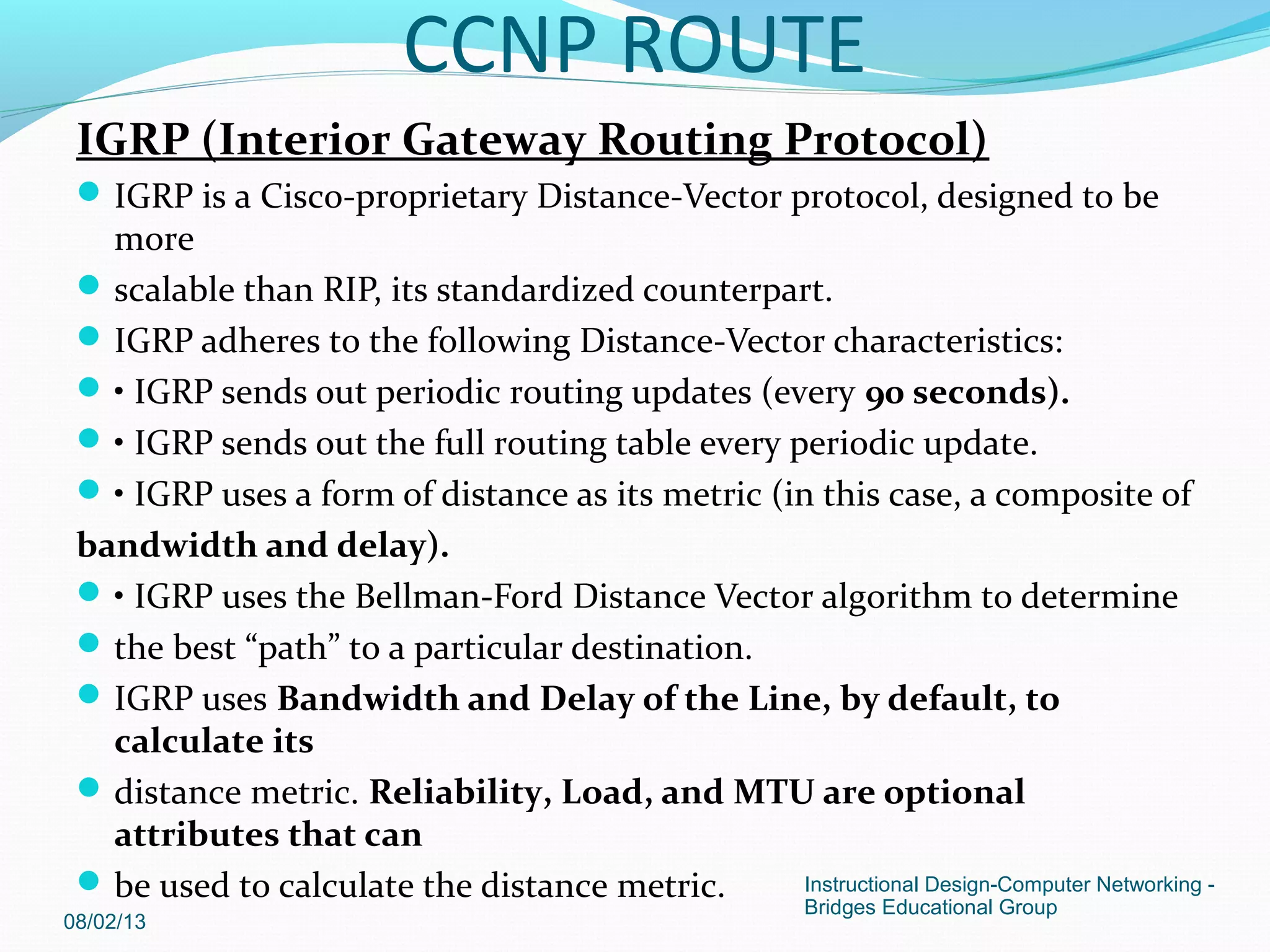
IGRP is a Cisco proprietary distance-vector routing protocol that is more scalable than RIP. IGRP uses bandwidth and delay as its metric to calculate the distance to destinations. IGRP has limitations when networks are not contiguous and have inconsistent subnet masks, as it may summarize routes incorrectly.

![The network statements tell IGRP which networks you wish to advertise
to other RIP routers. We simply list the networks that are directly
connected to our router. Notice that we specify the networks at their
classful boundaries,and we do not specify a subnet mask.
To configure Router B:
Router(config)# router igrp 10
Router(config-router)# network 172.17.0.0
Router(config-router)# network 172.18.0.0
The routing table on Router A will look like:
RouterA# show ip route
Gateway of last resort is not set
C 172.16.0.0 is directly connected, Ethernet0
C 172.17.0.0 is directly connected, Serial0
I 172.18.0.0 [120/1] via 172.17.1.2, 00:00:00, Serial0
08/02/13
Instructional Design-Computer Networking -
Bridges Educational Group](https://image.slidesharecdn.com/ccnproute-130802142430-phpapp02/75/Ccnp-route-5-2048.jpg)
![The routing table on Router B will look like:
RouterB# show ip route
Gateway of last resort is not set
C 172.17.0.0 is directly connected, Serial0
C 172.18.0.0 is directly connected, Ethernet0
I 172.16.0.0 [120/1] via 172.17.1.1, 00:00:00, Serial0
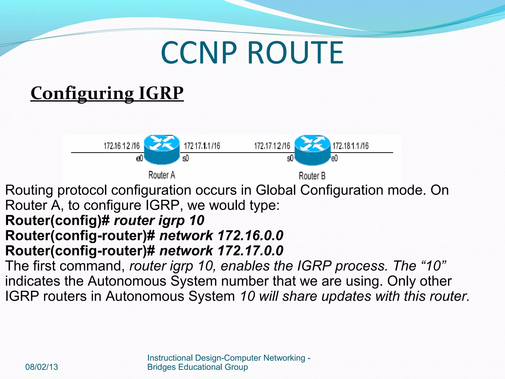
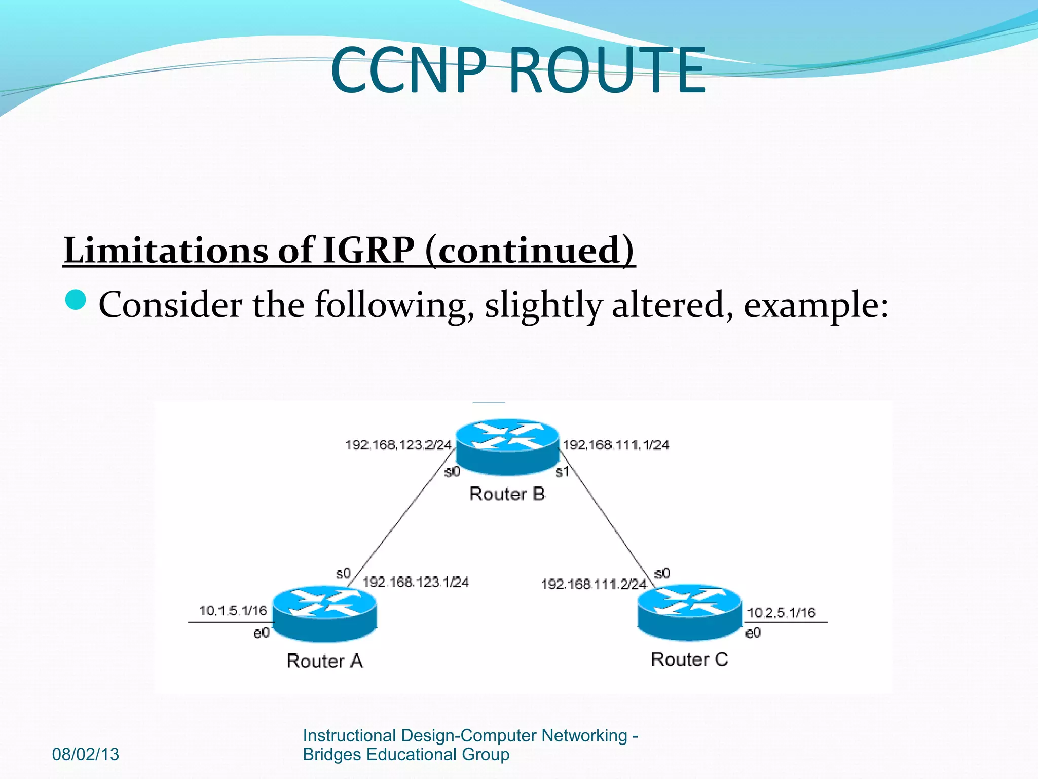
Limitations of IGRP
The example on the previous page works fine with IGRP, because the
networks are contiguous and the subnet masks are consistent.
Consider the
following example:
08/02/13
Instructional Design-Computer Networking -
Bridges Educational Group
CCNP ROUTE](https://image.slidesharecdn.com/ccnproute-130802142430-phpapp02/75/Ccnp-route-6-2048.jpg)
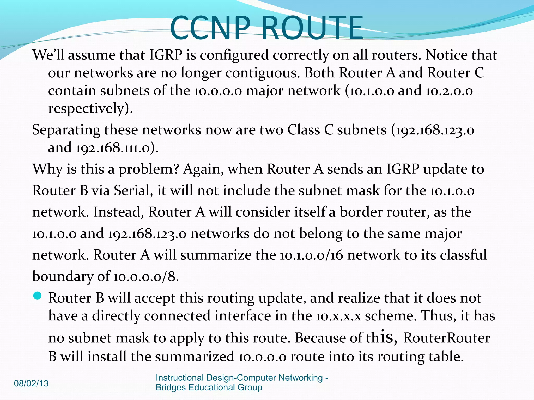
![Router B will accept this routing update, and realize that the interface
receiving the update (Serial0) belongs to the same major network as
the route entry of 10.1.0.0. It will then apply the subnet mask of its
Serial0 interface to this route entry.
Router C will similarly send an entry for the 10.2.0.0 network to Router B.
Router B’s routing table will thus look like:
RouterB# show ip route
Gateway of last resort is not set
10.0.0.0/16 is subnetted, 4 subnets
C 10.3.0.0 is directly connected, Serial0
C 10.4.0.0 is directly connected, Serial1
I 10.1.0.0 [120/1] via 10.3.5.1, 00:00:00, Serial0
I 10.2.0.0 [120/1] via 10.4.5.1, 00:00:00, Serial1
08/02/13
Instructional Design-Computer Networking -
Bridges Educational Group
CCNP ROUTE](https://image.slidesharecdn.com/ccnproute-130802142430-phpapp02/75/Ccnp-route-8-2048.jpg)
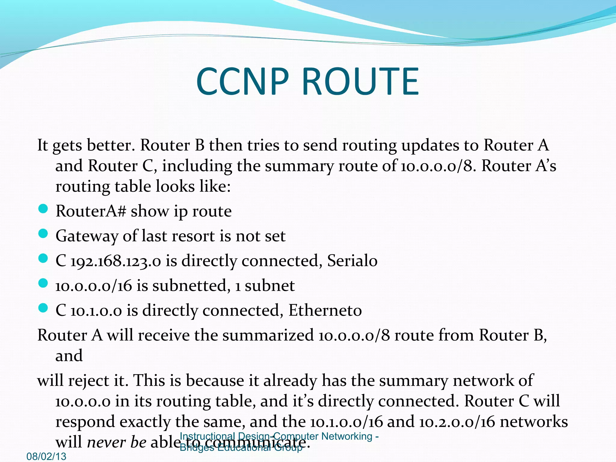
![Router C, similarly, will consider itself a border router between networks
10.2.0.0 and 192.168.111.0. Thus, Router C will also send a summarized
10.0.0.0 route to Router B.
Router B’s routing table will then look like:
RouterB# show ip route
Gateway of last resort is not set
C 192.168.123.0 is directly connected, Serial0
C 192.168.111.0 is directly connected, Serial1
I 10.0.0.0 [120/1] via 192.168.123.1, 00:00:00, Serial0
[120/1] via 192.168.111.2, 00:00:00, Serial1
That’s right, Router B now has two equal metric routes to get to the
summarized 10.0.0.0 network, one through Router A and the other
through Router C. Router B will now load balance all traffic to any
10.x.x.x network between routers A and C. Suffice to say, this is not a
good thing.
08/02/13
Instructional Design-Computer Networking -
Bridges Educational Group
CCNP ROUTE](https://image.slidesharecdn.com/ccnproute-130802142430-phpapp02/75/Ccnp-route-11-2048.jpg)


![Coded Agents – with UiPath SDK + LangGraph [Virtual Hands-on Workshop]](https://cdn.slidesharecdn.com/ss_thumbnails/codedagentsdeck-251215155422-5497c599-thumbnail.jpg?width=640&height=640&fit=bounds)


