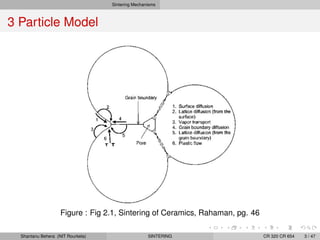
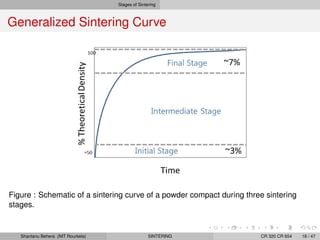
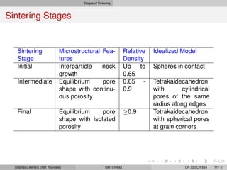
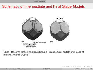
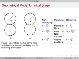
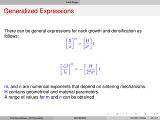
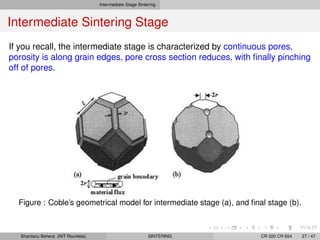
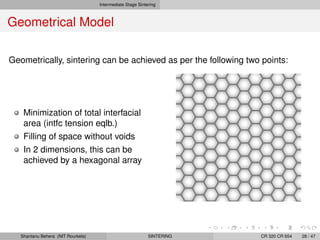
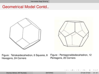
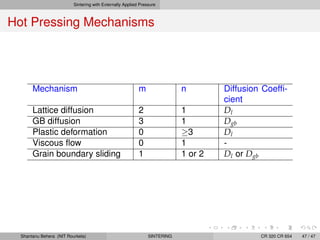
Solid State Sintering
Shantanu K Behera
Dept of Ceramic Engineering
NIT Rourkela
CR 320 CR 654
Shantanu Behera (NIT Rourkela) SINTERING CR 320 CR 654 1 / 47
Chapter Outline
1 Sintering Mechanisms
2 Scaling Law
3 Stages of Sintering
4 Initial Stage
5 Intermediate Stage Sintering
6 Final Stage Sintering: Geometrical Model
7 Sintering with Externally Applied Pressure
Shantanu Behera (NIT Rourkela) SINTERING CR 320 CR 654 2 / 47
Sintering Mechanisms
3 Particle Model
Figure : Fig 2.1, Sintering of Ceramics, Rahaman, pg. 46
Shantanu Behera (NIT Rourkela) SINTERING CR 320 CR 654 3 / 47
Sintering Mechanisms
Sintering Mechanisms and Routes
Mechanisms Source Sink Densifying
Surface Diffusion Surface Neck No
Lattice Diffusion Surface Neck No
GB Diffusion GB Neck Yes
Lattice Diffusion GB Neck Yes
Vapor Transport Surface Neck No
Plastic Flow Dislocations Neck Yes
Note that mechanisms that extend the GB region (solid-solid interface) are
densifying mechanisms. That keep the solid-vapor interface are
non-densifying mechanisms.
Shantanu Behera (NIT Rourkela) SINTERING CR 320 CR 654 4 / 47
Sintering Mechanisms
3 Particle Model
Calculate the free energy (surface related) difference between a set of
particles, and the same set of particles when sintered.
Note that the net reduction in energy would be equal to the total grain
boundary energy less the total surface (solid-vapor) energy.
Ed = As(
γgb
2
− γsv)
Shantanu Behera (NIT Rourkela) SINTERING CR 320 CR 654 5 / 47
Sintering Mechanisms
Curvature
Figure : Curvature in solids, and their effect of vacancy concentration
Shantanu Behera (NIT Rourkela) SINTERING CR 320 CR 654 6 / 47
Sintering Mechanisms
Vacancy under a Curved Surface
Chemical potential of atoms in a crystal can be written as
µa = µoa + pΩa + kBT ln Ca
Similarly, chemical potential of vacancies in a crystal can be written as
µv = µov + pΩv + kBT ln Cv
Chemical potential of vacancies under a curved surface can be written as
µv = µov + (p + γsvκ)Ω + kBT ln Cv
where κ = 1
R1
+ 1
R2
Accordingly, the equilibrium vacancy concentration
beneath a curved surface
Cv = Co,ve
−γsvκΩ
kBT
For γsvκΩ << kBT, this reduces to
Cv
Co,v
= 1 −
γsvκΩ
kBT
Shantanu Behera (NIT Rourkela) SINTERING CR 320 CR 654 7 / 47
Sintering Mechanisms
Vapor Pressure over a Curved Surface
Figure : Curvature in solids, and their effect on vapor pressure
Shantanu Behera (NIT Rourkela) SINTERING CR 320 CR 654 8 / 47
Sintering Mechanisms
Vapor Pressure over a Curved Surface
Vapor pressure over a curved surface can be defined as
Pvap = P0e
γsvκΩ
kBT
This simplifies to:
Pvap = P0 1 +
γsvκΩ
kBT
Shantanu Behera (NIT Rourkela) SINTERING CR 320 CR 654 9 / 47
Sintering Mechanisms
Diffusional Flux Equations
The general expression for flux:
J =
−DiC
kBT
dµ
dx
Flux of atoms:
Ja =
−DaCa
ΩkBT
d(µa − µv)
dx
Flux of vacancies and atoms are opposite to each other:
Ja = −Jv
Flux of vacancies:
Jv =
−DvCv
ΩkBT
dµv
dx
=
−Dv
Ω
dCv
dx
Shantanu Behera (NIT Rourkela) SINTERING CR 320 CR 654 10 / 47
Scaling Law
Herring’s Scaling Law
Length scale is an important parameter in sintering.
How does the change of scale (e.g. particle size) influence the rate of
sintering?
The law is based on simple models and assumptions.
Particle size remains the same.
Similar geometrical changes in different powder systems.
Similar composition.
Shantanu Behera (NIT Rourkela) SINTERING CR 320 CR 654 11 / 47
Scaling Law
Herring’s Scaling Law
Define λ as the numerical factor
Say, λ = a2
a1
, where a is the radius of the particle
Similarly, λ = X2
X1
, where X is the neck dimension of the two particle system.
Time required to produce a certain change by diffusional flux can be written as
t =
V
JA
Comparing two systems, we can write
t2
t1
=
V2J1A1
V1J2A2
Shantanu Behera (NIT Rourkela) SINTERING CR 320 CR 654 12 / 47
Scaling Law
Scaling Law for Lattice Diffusion
While comparing two spherical particles of sizes, a1 and a2, we can say that
the volume of matter transported is V1 ∝ a3
1, and V2 ∝ a3
2. And since λ = a2
a1
,
we can write V2 = λ3
Va.
Similarly A2 = λ2
A1
Again, flux (J) is ∝ the gradient in chemical potential (i.e. µ)
µ varies as 1
r , Therefore, J ∝ 1
r , Or J ∝ 1
r2
Therefore, J2 = J1
λ2
Summary: the parameters for lattice diffusion are:
V2 = λ3
V1; A2 = λ2
A1; J2 = J1
λ2
Comparing two systems, we can write
t2
t1
= λ3
=
a2
a1
3
Shantanu Behera (NIT Rourkela) SINTERING CR 320 CR 654 13 / 47
Scaling Law
Scaling Law for Other Mechanisms
In a general form, we can write as:
t2
t1
= λn
=
a2
a1
3
where m is the exponent that depends on the mechanism of sintering. Some
of the exponents for different mechanisms are as follows.
Sintering Mechanisms Exponent
Surface Diffusion 4
Lattice Diffusion 3
GB Diffusion 4
Vapor Transport 2
Plastic Flow 1
Viscous Flow 1
Shantanu Behera (NIT Rourkela) SINTERING CR 320 CR 654 14 / 47
Scaling Law
Relative Rates of Mechanisms
For a given microstructural change tha rate is inversely proportional to the
time required for the change. Therefore,
Rate2
Rate1
= λ−n
If grain boundary diffusion is the
dominant mechanism; then
Rategb = λ−4
If evaporation-condensation is the
dominant mechanism; then
Rateec = λ−2
Figure : Relative rates of sintering for GB
and EC as a function of length scale
Shantanu Behera (NIT Rourkela) SINTERING CR 320 CR 654 15 / 47
Stages of Sintering
Generalized Sintering Curve
Figure : Schematic of a sintering curve of a powder compact during three sintering
stages.
Shantanu Behera (NIT Rourkela) SINTERING CR 320 CR 654 16 / 47
Stages of Sintering
Sintering Stages
Sintering
Stage
Microstructural Fea-
tures
Relative
Density
Idealized Model
Initial Interparticle neck
growth
Up to
0.65
Spheres in contact
Intermediate Equilibrium pore
shape with continu-
ous porosity
0.65 -
0.9
Tetrakaidecahedron
with cylindrical
pores of the same
radius along edges
Final Equilibrium pore
shape with isolated
porosity
≥0.9 Tetrakaidecahedron
with spherical pores
at grain corners
Shantanu Behera (NIT Rourkela) SINTERING CR 320 CR 654 17 / 47
Stages of Sintering
Sintering Stage Microstructures (Real)
Initial stage (a)
rapid interparticle growth (various
mechanisms), neck formation,
linear shrinkage of 3-5%.
Intermediate stage (b)
Continuous pores, porosity is
along grain edges, pore cross
section reduces, finally pores
pinch off. Up to 0.9 of TD.
Final stage (c)
Isolated pores at grain corners,
pores gradually shrink and
disappear. From 0.9 to TD.
Shantanu Behera (NIT Rourkela) SINTERING CR 320 CR 654 18 / 47
Stages of Sintering
Schematic of Intermediate and Final Stage Models
Figure : Idealized models of grains during (a) intermediate, and (b) final stage of
sintering. After R L Coble
Shantanu Behera (NIT Rourkela) SINTERING CR 320 CR 654 19 / 47
Initial Stage
Geometrical Model for Initial Stage
Figure : Geometrical models for the initial
sintering stage; (a) non-densifying, and (b)
densifying mechanism.
Non-
densifying
Parameter Densifying
r = X2
2a Radius of
Neck
r = X2
4a
r = π2
X3
a Area of
Neck
Surface
A = π2
X3
2a
r = πX4
2a Volume
into Neck
r = πX4
8a
Shantanu Behera (NIT Rourkela) SINTERING CR 320 CR 654 20 / 47
Initial Stage
Kinetic Equations
Flux of atoms into the neck
Ja =
Dv
Ω
dCv
dx
Volume of matter transported to neck per unit time
dV
dt
= JaAgbΩ
Note that Agb = 2πXδgb Therefore,
dV
dt
= Dv2πXδgb
dCv
dx
Assuming that the vacancy concentration between surface and neck remains
constant dCv
dx = Cv
X Therefore,
Cv = Cv − Cvo =
CvoγsvΩ
kBT
1
r1
+
1
r2
Shantanu Behera (NIT Rourkela) SINTERING CR 320 CR 654 21 / 47
Initial Stage
Kinetic Equations Contd..
If we take r1 = r and r2 = −X, and assuming X >> r, we have
dV
dt
=
2πDvCvoδgbγsvΩ
kBTr
Using dV
dt from geometrical model, and Dgb = DvCvo,
πX3
2a
dX
dt
=
2πDgbδgbγsvΩa2
kBT
4a
X2
On simplification
X5
dX =
16DgbδgbγsvΩa2
kBT
dt
Upon integrating
X6
=
96DgbδgbγsvΩa2
kBT
t
We can write in another form:
X
a
=
96DgbδgbγsvΩa2
kBTa4
1
6
t
1
6
Shantanu Behera (NIT Rourkela) SINTERING CR 320 CR 654 22 / 47
Initial Stage
Kinetic Equations Contd..
X
a
=
96DgbδgbγsvΩ
kBTa4
1
6
t
1
6
This expression tells you that the ratio of neck radius to the sphere radius
increases as t
1
6 . For densifying mechanisms the shrinkage can be measured
as the change in length over original length.
l
l0
= −
r
a
= −
X2
4a2
Therefore
l
l0
=
3DgbδgbγsvΩ
kBTa4
1
3
t
1
3
The shrinkage is therefore predcited to increase as t
1
3
Shantanu Behera (NIT Rourkela) SINTERING CR 320 CR 654 23 / 47
Initial Stage
Kinetic Equations for Viscous Flow
Rate of energy dissipation by viscous flow should equal to rate of energy
gained by reduction in surface area.
The final expression looks like
X
a
=
3γsv
2ηa
1
2
t
1
2
How would the expression for shrinkage by viscous flow look like?
l
l0
=
3γsv
8ηa
t
Shantanu Behera (NIT Rourkela) SINTERING CR 320 CR 654 24 / 47
Initial Stage
Generalized Expressions
There can be general expressions for neck growth and densification as
follows:
X
a
m
=
H
an
t
l
l0
m
2
= −
H
2man
t
m, and n are numerical exponents that depend on sintering mechanisms.
H contains geometrical and material parameters.
A range of values for m and n can be obtained.
Shantanu Behera (NIT Rourkela) SINTERING CR 320 CR 654 25 / 47
Initial Stage
Summary: Initial Sintering Stage
Mechanism m n H♥
Surface diffusion♦
7 4 56DsδsγsvΩ/kBT
Lattice diffusion from sur-
face♦
5 3 20DlγsvΩ/kBT
Vapor transport♦
3 2 3P0γsvΩ/(2πmkBT)1/2
kBT
GB diffusion 6 4 96DgbδgbγsvΩ/kBT
Lattice diffusion from GB 4 3 80πDlγsvΩ/kBT
Viscous flow 2 1 3γsv/2η
♦
- non-densifying mechanism
♥
- Diffusion coefficients and constants with usual meanings.
If you recall, the exponent n here is same as the Herring’s Scaling Law
exponent.
Also note that, for nondensifying mechanisms m is an odd number.
Shantanu Behera (NIT Rourkela) SINTERING CR 320 CR 654 26 / 47
Intermediate Stage Sintering
Intermediate Sintering Stage
If you recall, the intermediate stage is characterized by continuous pores,
porosity is along grain edges, pore cross section reduces, with finally pinching
off of pores.
Figure : Coble’s geometrical model for intermediate stage (a), and final stage (b).
Shantanu Behera (NIT Rourkela) SINTERING CR 320 CR 654 27 / 47
Intermediate Stage Sintering
Geometrical Model
Geometrically, sintering can be achieved as per the following two points:
Minimization of total interfacial
area (intfc tension eqlb.)
Filling of space without voids
In 2 dimensions, this can be
achieved by a hexagonal array
Shantanu Behera (NIT Rourkela) SINTERING CR 320 CR 654 28 / 47
Intermediate Stage Sintering
Geometrical Model Contd..
In 3D tension equilibrium
requirement: 6 planes (grain
boundaries) and 4 lines (grain
edges) meet.
So, the number of corners that are
needed for a grain to be in
equilibrium is 22.8.
Two possible structures:
pentagonaldodecahedron and
tetrakaidecahedron.
Shantanu Behera (NIT Rourkela) SINTERING CR 320 CR 654 29 / 47
Intermediate Stage Sintering
Tetrakaidecahedron
Figure : Formation of a Tetrakaidecahedron from an octahedron; Source: Rahaman
Shantanu Behera (NIT Rourkela) SINTERING CR 320 CR 654 30 / 47
Intermediate Stage Sintering
Geometrical Model Contd..
Figure : Tetrakaidecahedron, 6 Squares, 8
Hexagons, 24 Corners
Figure : Pentagonaldodecahedron, 12
Pentagons, 20 Corners
Shantanu Behera (NIT Rourkela) SINTERING CR 320 CR 654 31 / 47
Intermediate Stage Sintering
Tetrakaidecahedron
Figure : Model of a piece of crystalline material with TKD units
Shantanu Behera (NIT Rourkela) SINTERING CR 320 CR 654 32 / 47
Intermediate Stage Sintering
Geometrical Model for Sintering
Space-filling array of equal sized tetrakaidecahedron, each of it describing
one particle. Cylindrical channel pores at TKD edges. Volume of
tetrakaidecahedron
Vt = 8
√
2l3
p
where lp is the edge length of the TKD. Total porosity (with r as the radius of
the pore)
Vp =
1
3
36πr2
lp
Therefore, porosity of the unit cell:
Vt
Vp
= Pc =
3π
2
√
2
r2
l2
p
Shantanu Behera (NIT Rourkela) SINTERING CR 320 CR 654 33 / 47
Intermediate Stage Sintering
Sintering Equations
For Lattice Diffusion:
1
ρ
dρ
dt
=
10DlγsvΩ
ρG3kBT
Densification rate at a fixed density scales inversely with the cube of grain size
(Check Herring’s law).
For Grain Boundary Diffusion:
1
ρ
dρ
dt
=
4
3
DgbδgbγsvΩ
ρ(1 − ρ)1/2G4kBT
Densification rate at a fixed density scales inversely with the fourth power of
grain size.
Shantanu Behera (NIT Rourkela) SINTERING CR 320 CR 654 34 / 47
Final Stage Sintering: Geometrical Model
Final Sintering Stage
Cylindrical pore channels pinch off
Pores become isolated
Pores at 4 grain junctions
Average density can be defined as:
ρ = 1 −
r
b
3
Number of pores per unit volume
N =
3
4π
1 − ρ
ρr3
Figure : Pore radius and improvement of
density
Shantanu Behera (NIT Rourkela) SINTERING CR 320 CR 654 35 / 47
Final Stage Sintering: Geometrical Model
Final Stage Sintering Equations
Porosity at time t:
Ps =
6π
√
2
DlγsvΩ
l3kBT
(tf − t)
For diffusion of atoms occurring by lattice diffusion:
dρ
dt LD
=
288DlγsvΩ
G3kBT
For diffusion occurring by grain boundary diffusion:
dρ
dt GBD
=
735DgbδgbγsvΩ
G4kBT
Shantanu Behera (NIT Rourkela) SINTERING CR 320 CR 654 36 / 47
Final Stage Sintering: Geometrical Model
Phenomenological Sintering Equation
In this approach, empirical equations are developed to fit experimental data
(ρ ∼ t)
ρ = ρ0 + K ln
t
t0
where K is a temperature dependent parameter.
For Coble’s lattice diffusion model:
dρ
dt
=
ADlγsvΩ
G3kBT
where A is a constant that relates to the sintering stage.
If grain coarsening occurs by (say) cubic law:
G3
− G3
0 = Kt
where G, G0 are grain sizes at time t and 0, and if, G3
G3
0, then
Shantanu Behera (NIT Rourkela) SINTERING CR 320 CR 654 37 / 47
Final Stage Sintering: Geometrical Model
Phenomenological Sintering Equation
densification can be written as:
dρ
dt
=
K
t
; K =
ADlγsvΩ
KG3kBT
This equation is expected to be valid for both intermediate and final stage
sintering.
When grain growth is limited, shrinkage can be fitted to the following form:
l
l0
= Kt
1
β
where K is a temperature dependent parameter, and β is an integer.
See that the above equation has a form similar to the initial sintering stage
model.
Shantanu Behera (NIT Rourkela) SINTERING CR 320 CR 654 38 / 47
Sintering with Externally Applied Pressure
Hot Pressing
Simultaneous application of pressure and temperature.
Figure : Schematic of a Hot Press Unit
Shantanu Behera (NIT Rourkela) SINTERING CR 320 CR 654 39 / 47
Sintering with Externally Applied Pressure
Analytical Model for Hot Pressing
Coble’s model can be changed with an additional stress term.
Cv,neck =
Cv,∞γsvΩ
kBT
κ
where Pe is External Pressure= φPa; φ is the stress intensification factor, Pa is
the applied pressure. Therefore,
Cv,boundary = −
Cv,∞γsvPe
kBT
= −
Cv,∞γsvφPa
kBT
For the initial stage:
C = Cv,neck − Cv,boundary =
Cv,∞Ω4a
kBTx2
γsv +
Paa
π
Shantanu Behera (NIT Rourkela) SINTERING CR 320 CR 654 40 / 47
Sintering with Externally Applied Pressure
Creep
Creep: Deformation due to
diffusion of atoms from
interfaces subjected to a
compressive stress (higher
chemical potential) to those
subjected to a tensile stress.
Shantanu Behera (NIT Rourkela) SINTERING CR 320 CR 654 41 / 47
Sintering with Externally Applied Pressure
Nabarro-Herring Creep
Lattice Diffusion
˙ =
dl
ldt
=
40
3
DlΩPa
G2kBT
Or
˙ ∝ G−2
Intermediate Stage
1
ρ
dρ
dt
=
40
3
DlΩ
G2kBT
Paφ +
γsv
r
Final Stage
1
ρ
dρ
dt
=
40
3
DlΩ
G2kBT
Paφ +
2γsv
r
Shantanu Behera (NIT Rourkela) SINTERING CR 320 CR 654 42 / 47
Sintering with Externally Applied Pressure
Coble Creep
Grain Boundary Diffusion
˙ =
95
2
DgbδgbΩPa
G3kBT
Or
˙ ∝ G−3
Intermediate Stage
1
ρ
dρ
dt
=
95
2
DgbδgbΩPa
G3kBT
Paφ +
γsv
r
Final Stage
1
ρ
dρ
dt
=
40
3
DgbδgbΩPa
G3kBT
Paφ +
2γsv
r
Shantanu Behera (NIT Rourkela) SINTERING CR 320 CR 654 43 / 47
Sintering with Externally Applied Pressure
Dislocation Creep
Application of higher stress induces matter transport by dislocation motion.
˙ =
ADµb
kBT
Pa
µ
n
Or
˙ ∝ Pn
a
Intermediate Stage
1
ρ
dρ
dt
= A
Dµb
kBT
Paφ
µ
n
Final Stage
1
ρ
dρ
dt
= B
Dµb
kBT
Paφ
µ
n
A, B are numerical constants.
Shantanu Behera (NIT Rourkela) SINTERING CR 320 CR 654 44 / 47
Sintering with Externally Applied Pressure
Densification rate in Hot Pressing
Since in the hot press, one of the dimension stays fixed, densification rate is
proportional to the rate of change in the thickness of the compact.
1
1
l
dl
dt
=
1
d
d(d)
dt
=
1
ρ
dρ
dt
So, simply, linear strain represents the densification rate. Can be obtained by
the travel distance of the hot press ram (plunger).
The driving force for sintering in hot press is the two different forces added
together: DF due to curvature and DF due to applied pressure.
DF = Pe + γsvκ = Paφ + γsvκ
Shantanu Behera (NIT Rourkela) SINTERING CR 320 CR 654 45 / 47
Sintering with Externally Applied Pressure
Hot Pressing Mechanisms
1
ρ
dρ
dt
=
HDφn
GmkBT
Pn
a
where H is a numerical constant
D is the diffusion coefficient
φ is the stress intensification factor
G is the grain size
m is the grain Size exponent
n is the stress exponent.
Shantanu Behera (NIT Rourkela) SINTERING CR 320 CR 654 46 / 47
Sintering with Externally Applied Pressure
Hot Pressing Mechanisms
Mechanism m n Diffusion Coeffi-
cient
Lattice diffusion 2 1 Dl
GB diffusion 3 1 Dgb
Plastic deformation 0 ≥3 Dl
Viscous flow 0 1 -
Grain boundary sliding 1 1 or 2 Dl or Dgb
Shantanu Behera (NIT Rourkela) SINTERING CR 320 CR 654 47 / 47

lecture-solid state sintering

  • 1.
    Solid State Sintering ShantanuK Behera Dept of Ceramic Engineering NIT Rourkela CR 320 CR 654 Shantanu Behera (NIT Rourkela) SINTERING CR 320 CR 654 1 / 47
  • 2.
    Chapter Outline 1 SinteringMechanisms 2 Scaling Law 3 Stages of Sintering 4 Initial Stage 5 Intermediate Stage Sintering 6 Final Stage Sintering: Geometrical Model 7 Sintering with Externally Applied Pressure Shantanu Behera (NIT Rourkela) SINTERING CR 320 CR 654 2 / 47
  • 3.
    Sintering Mechanisms 3 ParticleModel Figure : Fig 2.1, Sintering of Ceramics, Rahaman, pg. 46 Shantanu Behera (NIT Rourkela) SINTERING CR 320 CR 654 3 / 47
  • 4.
    Sintering Mechanisms Sintering Mechanismsand Routes Mechanisms Source Sink Densifying Surface Diffusion Surface Neck No Lattice Diffusion Surface Neck No GB Diffusion GB Neck Yes Lattice Diffusion GB Neck Yes Vapor Transport Surface Neck No Plastic Flow Dislocations Neck Yes Note that mechanisms that extend the GB region (solid-solid interface) are densifying mechanisms. That keep the solid-vapor interface are non-densifying mechanisms. Shantanu Behera (NIT Rourkela) SINTERING CR 320 CR 654 4 / 47
  • 5.
    Sintering Mechanisms 3 ParticleModel Calculate the free energy (surface related) difference between a set of particles, and the same set of particles when sintered. Note that the net reduction in energy would be equal to the total grain boundary energy less the total surface (solid-vapor) energy. Ed = As( γgb 2 − γsv) Shantanu Behera (NIT Rourkela) SINTERING CR 320 CR 654 5 / 47
  • 6.
    Sintering Mechanisms Curvature Figure :Curvature in solids, and their effect of vacancy concentration Shantanu Behera (NIT Rourkela) SINTERING CR 320 CR 654 6 / 47
  • 7.
    Sintering Mechanisms Vacancy undera Curved Surface Chemical potential of atoms in a crystal can be written as µa = µoa + pΩa + kBT ln Ca Similarly, chemical potential of vacancies in a crystal can be written as µv = µov + pΩv + kBT ln Cv Chemical potential of vacancies under a curved surface can be written as µv = µov + (p + γsvκ)Ω + kBT ln Cv where κ = 1 R1 + 1 R2 Accordingly, the equilibrium vacancy concentration beneath a curved surface Cv = Co,ve −γsvκΩ kBT For γsvκΩ << kBT, this reduces to Cv Co,v = 1 − γsvκΩ kBT Shantanu Behera (NIT Rourkela) SINTERING CR 320 CR 654 7 / 47
  • 8.
    Sintering Mechanisms Vapor Pressureover a Curved Surface Figure : Curvature in solids, and their effect on vapor pressure Shantanu Behera (NIT Rourkela) SINTERING CR 320 CR 654 8 / 47
  • 9.
    Sintering Mechanisms Vapor Pressureover a Curved Surface Vapor pressure over a curved surface can be defined as Pvap = P0e γsvκΩ kBT This simplifies to: Pvap = P0 1 + γsvκΩ kBT Shantanu Behera (NIT Rourkela) SINTERING CR 320 CR 654 9 / 47
  • 10.
    Sintering Mechanisms Diffusional FluxEquations The general expression for flux: J = −DiC kBT dµ dx Flux of atoms: Ja = −DaCa ΩkBT d(µa − µv) dx Flux of vacancies and atoms are opposite to each other: Ja = −Jv Flux of vacancies: Jv = −DvCv ΩkBT dµv dx = −Dv Ω dCv dx Shantanu Behera (NIT Rourkela) SINTERING CR 320 CR 654 10 / 47
  • 11.
    Scaling Law Herring’s ScalingLaw Length scale is an important parameter in sintering. How does the change of scale (e.g. particle size) influence the rate of sintering? The law is based on simple models and assumptions. Particle size remains the same. Similar geometrical changes in different powder systems. Similar composition. Shantanu Behera (NIT Rourkela) SINTERING CR 320 CR 654 11 / 47
  • 12.
    Scaling Law Herring’s ScalingLaw Define λ as the numerical factor Say, λ = a2 a1 , where a is the radius of the particle Similarly, λ = X2 X1 , where X is the neck dimension of the two particle system. Time required to produce a certain change by diffusional flux can be written as t = V JA Comparing two systems, we can write t2 t1 = V2J1A1 V1J2A2 Shantanu Behera (NIT Rourkela) SINTERING CR 320 CR 654 12 / 47
  • 13.
    Scaling Law Scaling Lawfor Lattice Diffusion While comparing two spherical particles of sizes, a1 and a2, we can say that the volume of matter transported is V1 ∝ a3 1, and V2 ∝ a3 2. And since λ = a2 a1 , we can write V2 = λ3 Va. Similarly A2 = λ2 A1 Again, flux (J) is ∝ the gradient in chemical potential (i.e. µ) µ varies as 1 r , Therefore, J ∝ 1 r , Or J ∝ 1 r2 Therefore, J2 = J1 λ2 Summary: the parameters for lattice diffusion are: V2 = λ3 V1; A2 = λ2 A1; J2 = J1 λ2 Comparing two systems, we can write t2 t1 = λ3 = a2 a1 3 Shantanu Behera (NIT Rourkela) SINTERING CR 320 CR 654 13 / 47
  • 14.
    Scaling Law Scaling Lawfor Other Mechanisms In a general form, we can write as: t2 t1 = λn = a2 a1 3 where m is the exponent that depends on the mechanism of sintering. Some of the exponents for different mechanisms are as follows. Sintering Mechanisms Exponent Surface Diffusion 4 Lattice Diffusion 3 GB Diffusion 4 Vapor Transport 2 Plastic Flow 1 Viscous Flow 1 Shantanu Behera (NIT Rourkela) SINTERING CR 320 CR 654 14 / 47
  • 15.
    Scaling Law Relative Ratesof Mechanisms For a given microstructural change tha rate is inversely proportional to the time required for the change. Therefore, Rate2 Rate1 = λ−n If grain boundary diffusion is the dominant mechanism; then Rategb = λ−4 If evaporation-condensation is the dominant mechanism; then Rateec = λ−2 Figure : Relative rates of sintering for GB and EC as a function of length scale Shantanu Behera (NIT Rourkela) SINTERING CR 320 CR 654 15 / 47
  • 16.
    Stages of Sintering GeneralizedSintering Curve Figure : Schematic of a sintering curve of a powder compact during three sintering stages. Shantanu Behera (NIT Rourkela) SINTERING CR 320 CR 654 16 / 47
  • 17.
    Stages of Sintering SinteringStages Sintering Stage Microstructural Fea- tures Relative Density Idealized Model Initial Interparticle neck growth Up to 0.65 Spheres in contact Intermediate Equilibrium pore shape with continu- ous porosity 0.65 - 0.9 Tetrakaidecahedron with cylindrical pores of the same radius along edges Final Equilibrium pore shape with isolated porosity ≥0.9 Tetrakaidecahedron with spherical pores at grain corners Shantanu Behera (NIT Rourkela) SINTERING CR 320 CR 654 17 / 47
  • 18.
    Stages of Sintering SinteringStage Microstructures (Real) Initial stage (a) rapid interparticle growth (various mechanisms), neck formation, linear shrinkage of 3-5%. Intermediate stage (b) Continuous pores, porosity is along grain edges, pore cross section reduces, finally pores pinch off. Up to 0.9 of TD. Final stage (c) Isolated pores at grain corners, pores gradually shrink and disappear. From 0.9 to TD. Shantanu Behera (NIT Rourkela) SINTERING CR 320 CR 654 18 / 47
  • 19.
    Stages of Sintering Schematicof Intermediate and Final Stage Models Figure : Idealized models of grains during (a) intermediate, and (b) final stage of sintering. After R L Coble Shantanu Behera (NIT Rourkela) SINTERING CR 320 CR 654 19 / 47
  • 20.
    Initial Stage Geometrical Modelfor Initial Stage Figure : Geometrical models for the initial sintering stage; (a) non-densifying, and (b) densifying mechanism. Non- densifying Parameter Densifying r = X2 2a Radius of Neck r = X2 4a r = π2 X3 a Area of Neck Surface A = π2 X3 2a r = πX4 2a Volume into Neck r = πX4 8a Shantanu Behera (NIT Rourkela) SINTERING CR 320 CR 654 20 / 47
  • 21.
    Initial Stage Kinetic Equations Fluxof atoms into the neck Ja = Dv Ω dCv dx Volume of matter transported to neck per unit time dV dt = JaAgbΩ Note that Agb = 2πXδgb Therefore, dV dt = Dv2πXδgb dCv dx Assuming that the vacancy concentration between surface and neck remains constant dCv dx = Cv X Therefore, Cv = Cv − Cvo = CvoγsvΩ kBT 1 r1 + 1 r2 Shantanu Behera (NIT Rourkela) SINTERING CR 320 CR 654 21 / 47
  • 22.
    Initial Stage Kinetic EquationsContd.. If we take r1 = r and r2 = −X, and assuming X >> r, we have dV dt = 2πDvCvoδgbγsvΩ kBTr Using dV dt from geometrical model, and Dgb = DvCvo, πX3 2a dX dt = 2πDgbδgbγsvΩa2 kBT 4a X2 On simplification X5 dX = 16DgbδgbγsvΩa2 kBT dt Upon integrating X6 = 96DgbδgbγsvΩa2 kBT t We can write in another form: X a = 96DgbδgbγsvΩa2 kBTa4 1 6 t 1 6 Shantanu Behera (NIT Rourkela) SINTERING CR 320 CR 654 22 / 47
  • 23.
    Initial Stage Kinetic EquationsContd.. X a = 96DgbδgbγsvΩ kBTa4 1 6 t 1 6 This expression tells you that the ratio of neck radius to the sphere radius increases as t 1 6 . For densifying mechanisms the shrinkage can be measured as the change in length over original length. l l0 = − r a = − X2 4a2 Therefore l l0 = 3DgbδgbγsvΩ kBTa4 1 3 t 1 3 The shrinkage is therefore predcited to increase as t 1 3 Shantanu Behera (NIT Rourkela) SINTERING CR 320 CR 654 23 / 47
  • 24.
    Initial Stage Kinetic Equationsfor Viscous Flow Rate of energy dissipation by viscous flow should equal to rate of energy gained by reduction in surface area. The final expression looks like X a = 3γsv 2ηa 1 2 t 1 2 How would the expression for shrinkage by viscous flow look like? l l0 = 3γsv 8ηa t Shantanu Behera (NIT Rourkela) SINTERING CR 320 CR 654 24 / 47
  • 25.
    Initial Stage Generalized Expressions Therecan be general expressions for neck growth and densification as follows: X a m = H an t l l0 m 2 = − H 2man t m, and n are numerical exponents that depend on sintering mechanisms. H contains geometrical and material parameters. A range of values for m and n can be obtained. Shantanu Behera (NIT Rourkela) SINTERING CR 320 CR 654 25 / 47
  • 26.
    Initial Stage Summary: InitialSintering Stage Mechanism m n H♥ Surface diffusion♦ 7 4 56DsδsγsvΩ/kBT Lattice diffusion from sur- face♦ 5 3 20DlγsvΩ/kBT Vapor transport♦ 3 2 3P0γsvΩ/(2πmkBT)1/2 kBT GB diffusion 6 4 96DgbδgbγsvΩ/kBT Lattice diffusion from GB 4 3 80πDlγsvΩ/kBT Viscous flow 2 1 3γsv/2η ♦ - non-densifying mechanism ♥ - Diffusion coefficients and constants with usual meanings. If you recall, the exponent n here is same as the Herring’s Scaling Law exponent. Also note that, for nondensifying mechanisms m is an odd number. Shantanu Behera (NIT Rourkela) SINTERING CR 320 CR 654 26 / 47
  • 27.
    Intermediate Stage Sintering IntermediateSintering Stage If you recall, the intermediate stage is characterized by continuous pores, porosity is along grain edges, pore cross section reduces, with finally pinching off of pores. Figure : Coble’s geometrical model for intermediate stage (a), and final stage (b). Shantanu Behera (NIT Rourkela) SINTERING CR 320 CR 654 27 / 47
  • 28.
    Intermediate Stage Sintering GeometricalModel Geometrically, sintering can be achieved as per the following two points: Minimization of total interfacial area (intfc tension eqlb.) Filling of space without voids In 2 dimensions, this can be achieved by a hexagonal array Shantanu Behera (NIT Rourkela) SINTERING CR 320 CR 654 28 / 47
  • 29.
    Intermediate Stage Sintering GeometricalModel Contd.. In 3D tension equilibrium requirement: 6 planes (grain boundaries) and 4 lines (grain edges) meet. So, the number of corners that are needed for a grain to be in equilibrium is 22.8. Two possible structures: pentagonaldodecahedron and tetrakaidecahedron. Shantanu Behera (NIT Rourkela) SINTERING CR 320 CR 654 29 / 47
  • 30.
    Intermediate Stage Sintering Tetrakaidecahedron Figure: Formation of a Tetrakaidecahedron from an octahedron; Source: Rahaman Shantanu Behera (NIT Rourkela) SINTERING CR 320 CR 654 30 / 47
  • 31.
    Intermediate Stage Sintering GeometricalModel Contd.. Figure : Tetrakaidecahedron, 6 Squares, 8 Hexagons, 24 Corners Figure : Pentagonaldodecahedron, 12 Pentagons, 20 Corners Shantanu Behera (NIT Rourkela) SINTERING CR 320 CR 654 31 / 47
  • 32.
    Intermediate Stage Sintering Tetrakaidecahedron Figure: Model of a piece of crystalline material with TKD units Shantanu Behera (NIT Rourkela) SINTERING CR 320 CR 654 32 / 47
  • 33.
    Intermediate Stage Sintering GeometricalModel for Sintering Space-filling array of equal sized tetrakaidecahedron, each of it describing one particle. Cylindrical channel pores at TKD edges. Volume of tetrakaidecahedron Vt = 8 √ 2l3 p where lp is the edge length of the TKD. Total porosity (with r as the radius of the pore) Vp = 1 3 36πr2 lp Therefore, porosity of the unit cell: Vt Vp = Pc = 3π 2 √ 2 r2 l2 p Shantanu Behera (NIT Rourkela) SINTERING CR 320 CR 654 33 / 47
  • 34.
    Intermediate Stage Sintering SinteringEquations For Lattice Diffusion: 1 ρ dρ dt = 10DlγsvΩ ρG3kBT Densification rate at a fixed density scales inversely with the cube of grain size (Check Herring’s law). For Grain Boundary Diffusion: 1 ρ dρ dt = 4 3 DgbδgbγsvΩ ρ(1 − ρ)1/2G4kBT Densification rate at a fixed density scales inversely with the fourth power of grain size. Shantanu Behera (NIT Rourkela) SINTERING CR 320 CR 654 34 / 47
  • 35.
    Final Stage Sintering:Geometrical Model Final Sintering Stage Cylindrical pore channels pinch off Pores become isolated Pores at 4 grain junctions Average density can be defined as: ρ = 1 − r b 3 Number of pores per unit volume N = 3 4π 1 − ρ ρr3 Figure : Pore radius and improvement of density Shantanu Behera (NIT Rourkela) SINTERING CR 320 CR 654 35 / 47
  • 36.
    Final Stage Sintering:Geometrical Model Final Stage Sintering Equations Porosity at time t: Ps = 6π √ 2 DlγsvΩ l3kBT (tf − t) For diffusion of atoms occurring by lattice diffusion: dρ dt LD = 288DlγsvΩ G3kBT For diffusion occurring by grain boundary diffusion: dρ dt GBD = 735DgbδgbγsvΩ G4kBT Shantanu Behera (NIT Rourkela) SINTERING CR 320 CR 654 36 / 47
  • 37.
    Final Stage Sintering:Geometrical Model Phenomenological Sintering Equation In this approach, empirical equations are developed to fit experimental data (ρ ∼ t) ρ = ρ0 + K ln t t0 where K is a temperature dependent parameter. For Coble’s lattice diffusion model: dρ dt = ADlγsvΩ G3kBT where A is a constant that relates to the sintering stage. If grain coarsening occurs by (say) cubic law: G3 − G3 0 = Kt where G, G0 are grain sizes at time t and 0, and if, G3 G3 0, then Shantanu Behera (NIT Rourkela) SINTERING CR 320 CR 654 37 / 47
  • 38.
    Final Stage Sintering:Geometrical Model Phenomenological Sintering Equation densification can be written as: dρ dt = K t ; K = ADlγsvΩ KG3kBT This equation is expected to be valid for both intermediate and final stage sintering. When grain growth is limited, shrinkage can be fitted to the following form: l l0 = Kt 1 β where K is a temperature dependent parameter, and β is an integer. See that the above equation has a form similar to the initial sintering stage model. Shantanu Behera (NIT Rourkela) SINTERING CR 320 CR 654 38 / 47
  • 39.
    Sintering with ExternallyApplied Pressure Hot Pressing Simultaneous application of pressure and temperature. Figure : Schematic of a Hot Press Unit Shantanu Behera (NIT Rourkela) SINTERING CR 320 CR 654 39 / 47
  • 40.
    Sintering with ExternallyApplied Pressure Analytical Model for Hot Pressing Coble’s model can be changed with an additional stress term. Cv,neck = Cv,∞γsvΩ kBT κ where Pe is External Pressure= φPa; φ is the stress intensification factor, Pa is the applied pressure. Therefore, Cv,boundary = − Cv,∞γsvPe kBT = − Cv,∞γsvφPa kBT For the initial stage: C = Cv,neck − Cv,boundary = Cv,∞Ω4a kBTx2 γsv + Paa π Shantanu Behera (NIT Rourkela) SINTERING CR 320 CR 654 40 / 47
  • 41.
    Sintering with ExternallyApplied Pressure Creep Creep: Deformation due to diffusion of atoms from interfaces subjected to a compressive stress (higher chemical potential) to those subjected to a tensile stress. Shantanu Behera (NIT Rourkela) SINTERING CR 320 CR 654 41 / 47
  • 42.
    Sintering with ExternallyApplied Pressure Nabarro-Herring Creep Lattice Diffusion ˙ = dl ldt = 40 3 DlΩPa G2kBT Or ˙ ∝ G−2 Intermediate Stage 1 ρ dρ dt = 40 3 DlΩ G2kBT Paφ + γsv r Final Stage 1 ρ dρ dt = 40 3 DlΩ G2kBT Paφ + 2γsv r Shantanu Behera (NIT Rourkela) SINTERING CR 320 CR 654 42 / 47
  • 43.
    Sintering with ExternallyApplied Pressure Coble Creep Grain Boundary Diffusion ˙ = 95 2 DgbδgbΩPa G3kBT Or ˙ ∝ G−3 Intermediate Stage 1 ρ dρ dt = 95 2 DgbδgbΩPa G3kBT Paφ + γsv r Final Stage 1 ρ dρ dt = 40 3 DgbδgbΩPa G3kBT Paφ + 2γsv r Shantanu Behera (NIT Rourkela) SINTERING CR 320 CR 654 43 / 47
  • 44.
    Sintering with ExternallyApplied Pressure Dislocation Creep Application of higher stress induces matter transport by dislocation motion. ˙ = ADµb kBT Pa µ n Or ˙ ∝ Pn a Intermediate Stage 1 ρ dρ dt = A Dµb kBT Paφ µ n Final Stage 1 ρ dρ dt = B Dµb kBT Paφ µ n A, B are numerical constants. Shantanu Behera (NIT Rourkela) SINTERING CR 320 CR 654 44 / 47
  • 45.
    Sintering with ExternallyApplied Pressure Densification rate in Hot Pressing Since in the hot press, one of the dimension stays fixed, densification rate is proportional to the rate of change in the thickness of the compact. 1 1 l dl dt = 1 d d(d) dt = 1 ρ dρ dt So, simply, linear strain represents the densification rate. Can be obtained by the travel distance of the hot press ram (plunger). The driving force for sintering in hot press is the two different forces added together: DF due to curvature and DF due to applied pressure. DF = Pe + γsvκ = Paφ + γsvκ Shantanu Behera (NIT Rourkela) SINTERING CR 320 CR 654 45 / 47
  • 46.
    Sintering with ExternallyApplied Pressure Hot Pressing Mechanisms 1 ρ dρ dt = HDφn GmkBT Pn a where H is a numerical constant D is the diffusion coefficient φ is the stress intensification factor G is the grain size m is the grain Size exponent n is the stress exponent. Shantanu Behera (NIT Rourkela) SINTERING CR 320 CR 654 46 / 47
  • 47.
    Sintering with ExternallyApplied Pressure Hot Pressing Mechanisms Mechanism m n Diffusion Coeffi- cient Lattice diffusion 2 1 Dl GB diffusion 3 1 Dgb Plastic deformation 0 ≥3 Dl Viscous flow 0 1 - Grain boundary sliding 1 1 or 2 Dl or Dgb Shantanu Behera (NIT Rourkela) SINTERING CR 320 CR 654 47 / 47