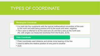
TYPES OF COORDINATE
•It is split into four quadrants with the typical mathematical convention of the axis
to the north and east being positive and to the south and west, negative.
• The x-axis is referred to as the east-axis (E) and the y-axis as the north-axis
(N), with angles (a) measured clockwise from the N-axis, (E,N)
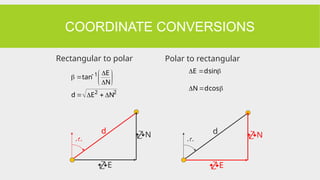
Rectangular Coordinate
• Polar coordinate used distance and whole circle bearing of the line
• Used to define the relative position of one point to another
• (d,β)
Polar Coordinate
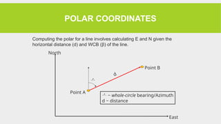
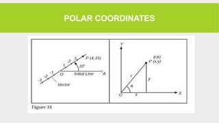
POLAR COORDINATES
d
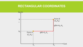
North
East
Point A
PointB
~ whole-circle bearing/Azimuth
d ~ distance
Computing the polar for a line involves calculating E and N given the
horizontal distance (d) and WCB (β) of the line.
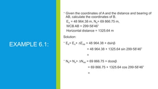
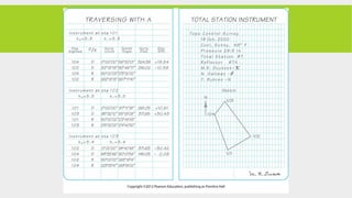
EXAMPLE 6.1:
Giventhe coordinates of A and the distance and bearing of
AB, calculate the coordinates of B.
EA = 48 964.38 m, NA= 69 866.75 m,
WCB AB = 299◦58’46”
Horizontal distance = 1325.64 m
Solution:
EB= EA+ ∆EAB = 48 964.38 + dsinβ
= 48 964.38 + 1325.64 sin 299◦58’46”
=
NB= NA+ ∆NAB = 69 866.75 + dcosβ
= 69 866.75 + 1325.64 cos 299◦58’46”
=
10.
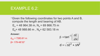
EXAMPLE 6.2:
Giventhe following coordinates for two points A and B,
compute the length and bearing of AB.
EA = 48 964.38 m, NA = 69 866.75 m
EB= 48 988.66 m , NB= 62 583.18 m
Answer:
dAB = 7283.61 m
β= 179◦48’33”
2
2
1
N
E
d
N
E
tan
11.
DEFINITIONS
Traverse
• Series ofstraight lines connecting
survey stations (begin at known points
as baseline)
Traversing
• Determination of horizontal coordinates
by measuring horizontal angles &
distances
12.
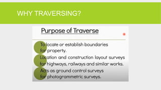
WHAT IS A
TRAVERSE?
Control survey
A series of established stations tied
together by angle and distance.
The angles are measured using
theodolites/total station/compass, while
distances can be measured using total
stations or tapes or EDM.
13.
WHAT IS ATRAVERSE?
A polygon of 2D (or 3D) vectors
Sides are expressed as either polar coordinates (,d) or as
rectangular coordinate differences (E,N)
A traverse must either close on itself
Or be measured between points with known rectangular
coordinates.
14.
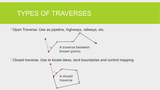
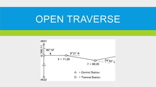
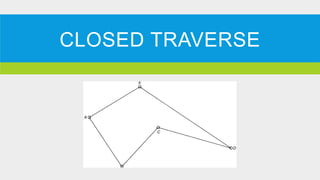
TYPES OF TRAVERSES
Open Traverse: Use as pipeline, highways, railways, etc.
Closed traverse: Use to locate lakes, land boundaries and control mapping
A closed
traverse
A traverse between
known points
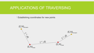
APPLICATIONS OF TRAVERSING
Establishing coordinates for new points
(
,
d
)
(,d)
(
,d)
(E,N)new
(E,N)new
(E,N)known
(E,N)known
19.
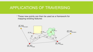
APPLICATIONS OF TRAVERSING
These new points can then be used as a framework for
mapping existing features
(
,
d
)
(
,d)
(,d)
(,d) (,d)
(
,
d
)
(E,N)new
(E,N)new
(E,N)new
(E,N)new
(E,N)new
(E,N)known
(E,N)known
20.
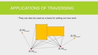
APPLICATIONS OF TRAVERSING
They can also be used as a basis for setting out new work
(E,N)new
(E,N)new
(E,N)known
(E,N)known
21.
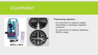
EQUIPMENT
Traversing requires:
An instrument to measure angles
(theodolite) or bearings (magnetic
compass)
An instrument to measure distances
(EDM or tape)
22.
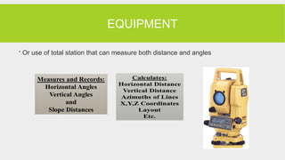
EQUIPMENT
Or useof total station that can measure both distance and angles
23.
OBSERVATION OF TRAVERSE
The methods used in observing angles and direction:
Interior Angles
To reduce mistakes in reading, recording and computing, always turned clockwise from
backsight station to foresight station
Angles to the right
To avoid ambiguity in angles to right, forward traverse station must be established.
Deflection Angles
For route survey
Azimuth
By total station, reading azimuth at all lines and thus eliminate the need to calculate
them.
24.
OBSERVATION OF TRAVERSE
Observation of traverse length
By simplest and economical ways
High precision
Use stationing
25.
CHOOSING LOCATION OF
TRAVERSESTATIONS
Some practical guidelines:
1. Minimum no. of stations (each line of sight as long as
possible)
2. Ensure: adjacent stations always inter-visible
3. Avoid acute traverse angles
4. Stable & safe ground conditions for instrument
5. Marked with paint or/and nail; to survive subsequent traffic,
construction, weather conditions, etc.
26.
CHOOSING LOCATION OFTRAVERSE
STATIONS
6. Include existing stations/reference objects for checking
with known values
7. Traverse must not cross itself
8. Network formed by stations (if any): as simple as
possible
9. Do the above without sacrificing accuracy or omitting
important details
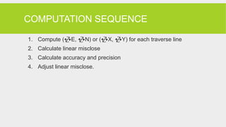
COMPUTATION SEQUENCE
1. Compute(E, N) or (X, Y) for each traverse line
2. Calculate linear misclose
3. Calculate accuracy and precision
4. Adjust linear misclose.
29.
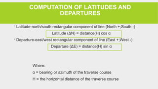
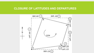
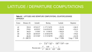
COMPUTATION OF LATITUDESAND
DEPARTURES
Latitude-north/south rectangular component of line (North +;South -)
Latitude (ΔN) = distance(H) cos α
Departure-east/west rectangular component of line (East +;West -)
Departure (ΔE) = distance(H) sin α
Where:
α = bearing or azimuth of the traverse course
H = the horizontal distance of the traverse course
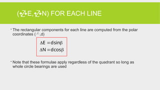
(E,N) FOR EACHLINE
The rectangular components for each line are computed from the polar
coordinates (,d)
Note that these formulae apply regardless of the quadrant so long as
whole circle bearings are used
cos
d
N
sin
d
E
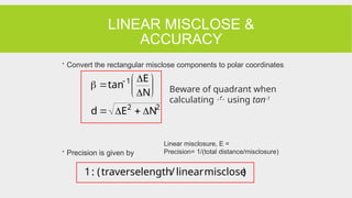
LINEAR MISCLOSE &
ACCURACY
Convert the rectangular misclose components to polar coordinates
Precision is given by
2
2
1
N
E
d
N
E
tan
)
misclose
linear
/
length
traverse
(
:
1
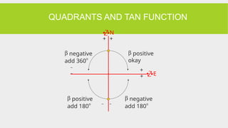
Beware of quadrant when
calculating using tan-1
Linear misclosure, E =
Precision= 1/(total distance/misclosure)
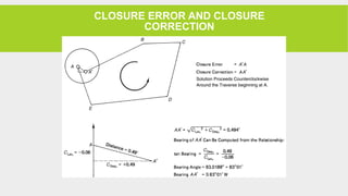
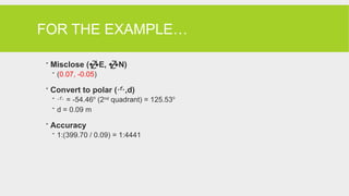
FOR THE EXAMPLE…
Misclose (E, N)
(0.07, -0.05)
Convert to polar (,d)
= -54.46o
(2nd
quadrant) = 125.53o
d = 0.09 m
Accuracy
1:(399.70 / 0.09) = 1:4441
40.
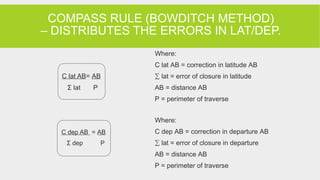
COMPASS RULE (BOWDITCHMETHOD)
– DISTRIBUTES THE ERRORS IN LAT/DEP.
Where:
C lat AB = correction in latitude AB
∑ lat = error of closure in latitude
AB = distance AB
P = perimeter of traverse
Where:
C dep AB = correction in departure AB
∑ lat = error of closure in departure
AB = distance AB
P = perimeter of traverse
C dep AB = AB
Σ dep P
C lat AB= AB
Σ lat P
41.
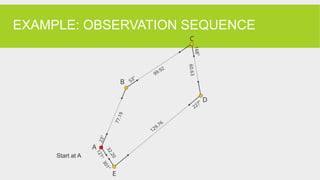
THE EXAMPLE…
Eastmisclose 0.07 m
North misclose –0.05 m
Side AB 77.19 m
Side BC 99.92 m
Side CD 60.63 m
Side DE 129.76 m
Side EA 32.20 m
Total perimeter 399.70 m
42.
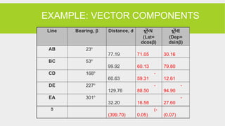
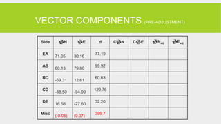
VECTOR COMPONENTS (PRE-ADJUSTMENT)
SideN E d CN CE Nadj Eadj
EA
71.05 30.16
77.19
AB
60.13 79.80
99.92
BC
-59.31 12.61
60.63
CD
-88.50 -94.90
129.76
DE
16.58 -27.60
32.20
Misc
(-0.05) (0.07)
399.7
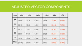
43.
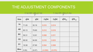
THE ADJUSTMENT COMPONENTS
SideN E CN CE Nadj Eadj
1A
71.05 30.16
-
0.010 0.014
AB
60.13 79.80
-
0.012 0.016
BC
-
59.31 12.61
-
0.008 0.011
CD
-
88.50
-
94.90
-
0.016 0.023
D1
16.58
-
27.60
-
0.004 0.006
Misc
(-
0.05) (0.07) (-0.050) (0.070)
C lat AB= AB X Σ lat
P
C dep AB= AB X Σ dep
P
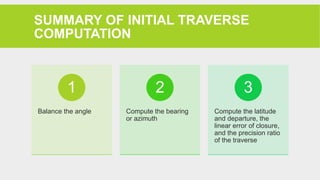
SUMMARY OF INITIALTRAVERSE
COMPUTATION
Balance the angle
1
Compute the bearing
or azimuth
2
Compute the latitude
and departure, the
linear error of closure,
and the precision ratio
of the traverse
3
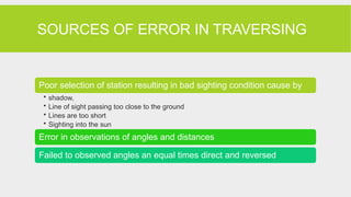
46.
SOURCES OF ERRORIN TRAVERSING
Poor selection of station resulting in bad sighting condition cause by
• shadow,
• Line of sight passing too close to the ground
• Lines are too short
• Sighting into the sun
Error in observations of angles and distances
Failed to observed angles an equal times direct and reversed
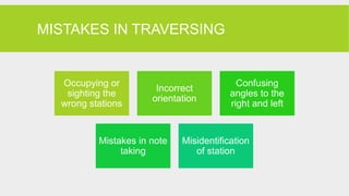
47.
MISTAKES IN TRAVERSING
Occupyingor
sighting the
wrong stations
Incorrect
orientation
Confusing
angles to the
right and left
Mistakes in note
taking
Misidentification
of station