Downloaded 10 times


![IMPLEMENTING DESIGN FOR MANUFACTURE RULES
R. Dumitrescu andT. Szecsi
School of Mechanical andManufacturing Engineering, Dublin City University, Ireland.
ABSTRACT
This paper shows a new approachin incorporating manufacturing constraints at the design
stageinto an intelligent system,which analysesthe designfeaturesfrom a CAD drawing, relates
them to machining features,andthen suggeststhe available manufacturing processescapableof
producing these features.The system also examineswhether design for manufacture rules are
violated by the features’ characteristics and conclude on their manufacturing possibility.
Production type? materials, tolerances, surface finish, and feature’s characteristics and
accessibility aretaken into consideration.
KEYWORDS: Design for Manufacture, Computer Aided Design (CAD), Design &
Machining Features
1. INTRODUCTION ,
Classically, the designing environment was basedon what we call today the “over-the-
wall” system [2], where the interaction between designersand manufacturing engineers was
minimal and manufacturing issueswere only superficially consideredfrom the beginning of a
design. One way of overcoming this problem is to have a team of designersand manufacturing
engineersworking together at the design stage. These teams use analysing tools, which help
them evaluatethe design.Design For Manufacture is oneof thesetools that enhancea numberof
general rules about the manufacturability of a part (i.e. the relative easeof manufacturing a
Par-Q
In the last years,Design For Manufacture (DFM) approachhasbecomea real interestas
it was found that the design stagedeterminesmost of the cost of the development of a product.
As market needshave increasedand the competition to remain on the market hasbecomevery
tight, it is a crucial issue to reduce the time of the product development [11.Customers are
demanding high quality products at competitive prices and the design is the first step in
satisfying their requirements [7]. Thus, it is necessaryto apply manufacturing constrainsfrom
the very beginning of the design stage,in order to avoid costly changesthat may occur later
becauseof the difficulty or impossibility to implement some manufacturing processes.This
practiceis essentialin reducingthe costof aproduct considerably.
The history of DFM is describedin [l] from the early beginning. Eli Whitney is known
asthe personwho introducedthe interchangeablepartsconcept.Still in a growing phase,DFM is
believed to become even more important in the next years. Nowadays, the increase of the
importance of the DFM conceptis closely relatedto the drastic developmentandhugeprogresses
Copyright (c) 2002 Society of Manufacturing Engineers. All rights reserved.](https://image.slidesharecdn.com/tp02pub31-140926101815-phpapp02/85/Tp02-pub31-3-320.jpg)
![2
achievedin computation resourcesduring the last decade,making available high performance
hardware and software at affordable prices. Although CAD systemshave been available since
almost 30 yearsandthey areprogressively spreadingin almost all fields of today’s engineering,
thereis still a lot to do in the field of computerisation of DFM [13.
The aim of this researchis the development of an intelligent system for implementing
DFM rules, which hasits origins in the idea of helping designersby offering them supportwith
manufacturing constraints information. The purpose is to improve the design quality and to
decreasethe time-to-market, as rapid product development is becoming a critical factor to a
company’sposition [2]. It is well known that improperly designedpartscan still beproducedbut
with anunjustifiable increasein manufacturing costsandtime, andit is the aim of the DFM tools
to help usersto optimise their designs.
In the following section of this paper, feature conceptterminology and usageare briefly
reviewed. The third and fourth sectionsexplain our approachand intentions in developing the
system.Discussionsand examplesof hole features are also included in the fourth section. The
capabilities and limitations of the approach are concluded in the fifth section, and the further
work planned to continue our researchand its perspectivesare explained. Some examples of
machining featuresaregiven in the annexat the endof thepaper.
2. FEATURE CONCEPT
The integration of CAD systemsto CAM and CAE systemscould not be achievedwithout
the help of feature concept.Indeed, CAPP hasto interpret the part from a CAD data in terms of
features [I 11,which most often are manufacturing features.Based on the viewpoint, different
types of features can be defined. During the design process, a part is created using design
features,which later have to be interpreted into manufacturing, assembly or inspection features
via dedicatedrecognition tools.
2.1 Feature Definition
A feature is a set of faces or regions of one part with distinct topological, geometrical
and/or manufacturing information. Featurescharacterisethe product and help in analysing the
design concurrently using numerical or knowledge-basedsystems[121.If the product is viewed
from the designing stand point. then features are called design features and they present only
topological and geometrical information; if the product is viewed from the manufacturing stand
point, then featuresare called manufacturing featuresand they presenttopological, geometrical
andmanufacturing Xorrnation.
In [S], a feature is defined as a stereotypical geometric shape associated with some
engineering significance. The authors also mention about the predefined feature, which has a
fixed topology and has been defined in a library. Another way of defining a feature is given in
[12], where a feature representsthe geometry of a part or assembly and building blocks for
product definition or for geometry reasoning. It hasto be mentioned that as the researchgoes
deeperinto this area,different typesof featuresaredevelopedsystematically.
2.2 Design Features
Design Featuresarethosefeaturesusedat the design stagedefined by the useror from the
CAD modeller library and which do not take into considerationany manufacturing, assemblyor
Copyright (c) 2002 Society of Manufacturing Engineers. All rights reserved.](https://image.slidesharecdn.com/tp02pub31-140926101815-phpapp02/85/Tp02-pub31-4-320.jpg)
![3
inspection constrains. They might have shapesand/or locations impossible to produce and/or
reachwith the available technology at a given moment and in a given company. [7] deals with
threetypes of design features:depression,protrusion, andtransition features.The authorsdefine
the depressionfeature asan increment to the volume of a shapesuchasboss,and the protrusion
featureas a decrementsuch as a hole. The transition feature could be either a decrementor an
increment,dependingon whether its profile is convexor concave.
Examples of design features can be found in [4,6,7] as slot, hole, pocket, rounding,
cylinder, block, protrusion, cut, chamfer, user-defined features, etc. The user-defined design
features are based on planar profiles swept into three-dimensional shapesby extrusions and
revolutions.
2.3 Feature-based Desiw
A systemwhere the designercreatesthe part by picking the entities from a feature library
is called a feature-baseddesign system [4]. Today’s CAD systemshave their own pre-defmed
featurelibrary. [4,12] show that the main advantagesof designing with featuresare the less-time
consuming aspectwhen re-design of a part is needed.In this case,once a parent-featureis re-
positioned it will automatically re-position all its child-features, as features are relatively
positionedoneagainstanother.Reuseof design is not usually the casein classicalCAD systems,
whereeverythinghad to bereconsideredalmost from the beginning.
When the feature library does not satisfy a company, a user-defin.edone adaptable to
different types of products can be createdwhere there is a real needfor this, as it is time and
moneyconsuming [9]. Still the creationof anadequatefeaturelibrary is not trivial.
2.4 Manufacturing Features
A manufacturing featureis interpreted in [8] asa continuous volume that can be removed
by a single machining operation in a single set-up.It dependsnot only on the shapeand size of
the geometric feature, but also on the manufacturing processto be usedto produce this feature
[9]. The definition of the manufacturing featuresis general&d in [lo] to the whole engineering
approach,as being a function of the part (or some portion of the part) and specific factory
resourcesto be usedto producethat (portion of the) part; from herethe authorsconcludethat a
manufacturingfeatureis the function of machinetools, setup,tools andparts.
It can be found in [5,6,1l] that there are different manufacturing features,namely: hole,
pocket,openpocket, face, boss,step,open step,slot, notch, grove, knurl, thread, fillet, chamfer,
etc.
2.5 Design by Manufacturing Features
Design by Manufacturing Featureswould be the most promising in the evolution of CAD
systems,where the designer would have to use manufacturing featuresand to think in process
planning terms,i.e. manufacturing techniquesandcostissues[9]. This approachassumesthat the
designercreatesthe part in terms of manufacturing operations. It would be the best to use in
practice,but it is still unnatural for the designers.
2.6 Manufacturability Analysis
Unfortunately, it is still impossible to completely replace the human decision factor with
an automatic manufacturing analysis system becausethe relation between design details and
Copyright (c) 2002 Society of Manufacturing Engineers. All rights reserved.](https://image.slidesharecdn.com/tp02pub31-140926101815-phpapp02/85/Tp02-pub31-5-320.jpg)
![4
processing is often very complex and not easily reduced to formulas or simple relationships.
Specifying a manufacturing processfor a feature is a difficult decision since for someparticular
situations onewell-known expensiveoperation can be cheaperthan two cheaperoperations and
an automatic selection of the manufacturing sequencemay ignore the expensive manufacturing
processesfor the two cheaperones.The main aim of this researchis to develop a systemwhich
helpsdesignersin making better designsin lesstime.
3. OVERVIEW OF THE APPROACH
As it wasmentioned in the first section,considerationof the manufacturing aspectsat the
design stageis very important as experiencehas shown that up to 70 per cent of the product’s
cost [2,7] is directly generated at the design stage. The final cost of the product may be
significantly increasedbecauseof an inefficient design of the product, an improper selection of
the material, production type or surfacefinish. Therefore, the design of one product is the most
suitable stagewhere changesand interventions with regardto the manufacturing aspectsshould
take place for an optimal manufacture. We presenthere an approachof an intelligent system,
which interactively assiststhe designerduring his or her work with manufacturing issues.
NowadaysCAD systems,when using, askfor precisegeometric data,which is more than
the designaspectof a part andthe designershouldcareonly aboutthe functional requirementsof
the part. This fact could push the designerto think about all the product’s specification. Yet, the
designer has no clear idea about the manufacturing processes’capability of
designedpart.
producing the
Fig. 1. Information Transfer
Copyright (c) 2002 Society of Manufacturing Engineers. All rights reserved.](https://image.slidesharecdn.com/tp02pub31-140926101815-phpapp02/85/Tp02-pub31-6-320.jpg)
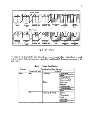
![7
If we refer only to the rotational andnon-rotational types of holes,the manufacturing processes
for producing them may significantly differ and therefore, a manufacturing analysis has to be
doneto decideuponthe appropriateprocessto beused.
After the feature mapping process (i.e. mapping of the design features into manufacturing
features), the manufacturability analysis module identifies, if any, the machining processes
capableof producing the required featureof the part, basedon the:
l production type,
l material type,
0 feature’scharacteristics,
l tolerancesand surfacefinish,
o feature’saccessibility andposition,
virhichthe designerhasto selectandprovide to the DFM system.
At the moment we decidedthat the manufacturing analysisprocesswill take into consideration
only the most common materials, the normal values for tolerances, surface finish and some
specific feature’s characteristics.In order to keep the product’s cost as low as possible, the
systemwill not take into consideration the closestvalues for tolerancesand surface finish. The
samerule appliesfor production type andparticular featurescharacteristics.
In the example below (Table 2), the feature considered is a cylindrical through hole. Its
characteristicsare the hole diameter, the hole depth and the depth-to-diameter ratio of the hole.
From the design stage,the geometrical and topological characteristicsare known. Further, the
designerhasto provide the DFM systemwith the information concerningthe production type he
or shewants to be usedwhen manufacturing the part, the material of the part, and the valuesof
tolerancesand surface finish to be achieved. After processing all this information, the most
suitable manufacturing processwill be selected for the specific feature. In our example, the
drilling processwas selectedfrom the library. Further, the constraintsof the drilling processare
applied to the hole and warn the designerabout the limitations of the this process.One of these
refersto the diameter size(concerningthe standardtill sizes),which cannotbe lessthan 1.5mm
orgreaterthan38mm [3].
Table 2: Manufacturability Analysis
Feature Production Material Surface Depth-to- Tolerances Manufacturing
Type Finish diameter [=a Processes
[run1 ratio
Cylindrical Mass Carbon 1.6-3.2 3:l *(0.05-0.25) Drilling
Through Production Steel
Hole
Another limitation of the drilling processfrom the economical point of view is the maximum
value of the depth-to-diameterratio, which should not exceed3:1. Although the applicability of
Copyright (c) 2002 Society of Manufacturing Engineers. All rights reserved.](https://image.slidesharecdn.com/tp02pub31-140926101815-phpapp02/85/Tp02-pub31-9-320.jpg)
![Through Slot Features
Round V-shaped
Slot Slot
Rectangular
Slot
Dovetail
Slot
FreeForm
Slot
T-shaped
Slot
Slot Features
Blind Pocket Open Pocket
Blind Freeform
Pocket
Open Freefarm
Pocket
PocketFeatures
References
Blind Slot Features
Rectangular
Slot
FreeForm
Slot
[l] JamesG. Bralla, Handbook of Product Designfor Manufacturing - A Practical Guide to
Low-CostProduction, McGraw-Hill Book Company, 1999.
Copyright (c) 2002 Society of Manufacturing Engineers. All rights reserved.](https://image.slidesharecdn.com/tp02pub31-140926101815-phpapp02/85/Tp02-pub31-12-320.jpg)
![PI
PI
PI
PI
WI
VI
VI
PI
G. Boothroyd, P. Dewhurst, W. Knight, Product Designfor Manufacture and Assembly,
Marcel Dekker, 1994.
Mahmoud M. Farag, Selection of Materials and Manufacturing Processes for
Engineering Design, PrenticeHall International Ltd., 1989.
D. Jacquel, J. Salmon, Design for Manufacturability: a feature-based agent-driven
approach,Pro.c Instn. A4ec.hEngrs., Vol2 14,PartB, 2000.
X. William Xu, Jack J. Ding, Integrating Design with Manufacturing, Proc. Pacific
Conferenceon Manufacturing, August 1998.
Jae Yeol Lee and Kwangsoo Kim, A feature-based approach to extracting machining
features, Elsevier, 1999.
D. T. Phamand S. S. Dimov, An approachto concurrentengineering,Proc lnstn Mech
Engrs, Vo1212,Part B, pg 13-27.
S. GaoandJ. J. Shah,Automatic recognition of interacting machiningfeatures basedon
minimal condition subgraph, Elsevier, 1999.
B. John Davies, CIM software and interfaces, Computersin Industry, Vol 33, pg 91-99,
1997.
[lo] R. Stage, C. Roberts, M. Handerson, Generating resource based flexible form
manufacturing featuresthrough objective driven clustering, Computer-AidedDesign, Vol
31,pg 119-130,1999.
[l l] X. Yan, K. Yamazaki, 9. Liu, Recognition of machining featuresand feature topologies
from NC programs,ComputerAided Design, Vol32, pg 605616,200O.
[121 Jami J ShahandMartti Mantyla, Parametric and Feature-BasedCADLCAM, 1995.
Copyright (c) 2002 Society of Manufacturing Engineers. All rights reserved.](https://image.slidesharecdn.com/tp02pub31-140926101815-phpapp02/85/Tp02-pub31-13-320.jpg)

This document describes the development of an intelligent system to incorporate manufacturing constraints into the design process. The system analyzes design features from a CAD drawing and relates them to machining features. It then determines which manufacturing processes can produce those features and whether any design for manufacturing rules have been violated. The system considers production type, materials, tolerances, surface finish, feature characteristics, and accessibility. Currently, the system focuses on classifying and analyzing hole features, such as through holes, blind holes, counterbored holes, etc. It determines the appropriate machining processes based on criteria like whether the hole has a rotational axis. The goal is to help designers create designs that are easier to manufacture.