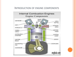
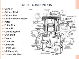
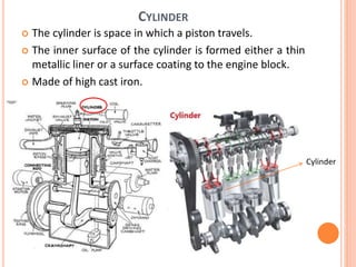
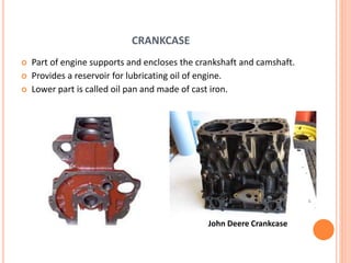
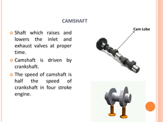
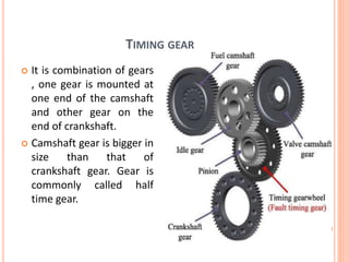
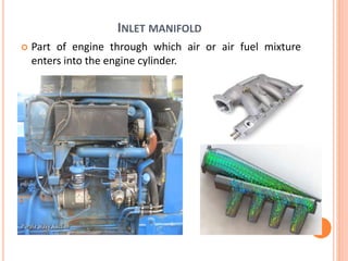
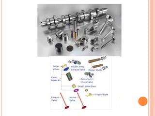
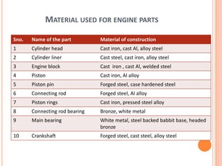
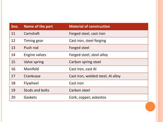
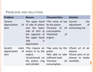
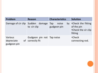
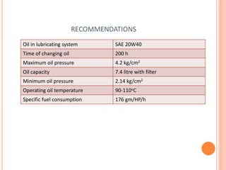
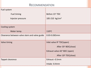
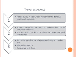
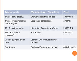
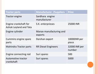
INTRODUCTION OF ENGINE
COMPONENTS
Purvi Tiwari
IGKV, Raipur (CG)
INTRODUCTION OF ENGINE COMPONENTS
ENGINE COMPONENTS
 Cylinder
 Cylinder Block
 Cylinder Head
 Cylinder Liner or Sleeve
 Piston
 Piston Ring
 Piston Pin
 Connecting Rod
 Crankshaft
 Flywheel
 Crankcase
 Camshaft
 Timing Gear
 Inlet Manifold
 Exhaust Manifold
CYLINDER
 The cylinder is space in which a piston travels.
 The inner surface of the cylinder is formed either a thin
metallic liner or a surface coating to the engine block.
 Made of high cast iron.
Cylinder
CYLINDER BLOCK
 Integrated structure comprising the cylinder of a
reciprocating engine .
It contains:-
• Cylinder
• Coolant passage
• Oil passage
• Bearings
CYLINDER HEAD
 It is the detachable portion of an engine which covers
the cylinder and includes the combustion chamber,
spark plug and valves.
GASKET
 A gasket is a mechanical seal which fills the space between
two or more mating surfaces, generally to prevent leakage
from or into the joined objects while under compression.
CYLINDER LINER OR SLEEVE
 It is installed to prevent the
damage of the walls of the
cylinder inside an engine
block.
 Dry sleeves are thin and
supported by the cylinder
block material. They are not
in direct contact with the
coolant and are generally
pressed into the block.
 Wet sleeves are directly
exposed to the coolant and
are thicker to account for
the lack of structural
support for the block.
PISTON
 Cylindrical part closed at
one end which maintains
a close sliding fit in the
engine cylinder.
 It is connected to the
connecting rod by a
piston pin.
 The force of the
expanding gases against
the closed end of the
piton, forces the piston
down in the cylinder.
 Made of cast iron.
 It is made of aluminium and
is alloy due to lightness.
Parts of Piston
• Head – top of the
piston
• Skirt- below the
piston pin designed
to absorb side
movement of piston.
Head
Skirt
TYPES OF PISTON
Dom type Cavity type Hill type
Flat type Concave type
PISTON RING
 Split expansion ring, placed in the groove of the piston.
 Made of cast iron or pressed steel alloy
Forms gas tight
combustion
chamber
Reduces contact
area between
cylinder wall and
piston wall
Controls the
cylinder lubrication
Transmit heat away
from the piston to
cylinder walls.
Functions of Piston
Rings
Piston rings are of two types:-
Compression ring
• A compression ring is the
piston ring located in
the ring groove closest to the
piston head.
• The compression ring seals the
combustion chamber from any
leakage during the combustion
process.
Oil ring
• Rings are slotted and located in
lowest groove above the piston
pin
• Control the distribution of
lubrication oil and prevent
excessive oil consumption.
• Oil ring is provided with small
holes through which excess oil
returns back to the crankcase
chamber
PISTON PIN
 It is also called Wrist pin or Gudgeon pin.
 It is used to join connecting rod to the piston.
 Made of case hardened alloy steel.
 Types of Gudgeon pin
• Pin fit in the piston bush and free in the small end
of connecting rod. After this stage both ends lock
by cir clip lock.
Full Floating Gudgeon Pin
• Pin is free to rotate in the piston bush and
connecting rod small end. The cir clip lock fit on
the both sides of gudgeon pin
Semi floating gudgeon pin
• Pin is only free in piston bush and fix in the small
end of connecting rod. Used in petrol engine.
Stationary gudgeon pin
CONNECTING ROD
 One end is attached to
the piston and other to
the crankshaft.
 It transmits the power of
combustion to the
crankshaft.
 It is made of drop forged
steel.
 Its small end is provided
with bearings, spilt into
two shells.
Split shells
CRANKSHAFT
 It is the main shaft of an engine which converts reciprocating
motion of piston into rotary motion of the flywheel.
 It is made of drop forged steel or cast steel.
Engine crankshaft of
Ashok Leyland and
TATA at Rs 25000/-
CRANK MECHANISM
FLYWHEEL
Functions of flywheel
Stored energy during power stroke and returns back same
energy.
Carries ring gear that meshes with pinion of starting motor
Rear surface serves as pressure surface for clutch plate
Serves the purpose of a pulley for transmitting power.
CRANKCASE
 Part of engine supports and encloses the crankshaft and camshaft.
 Provides a reservoir for lubricating oil of engine.
 Lower part is called oil pan and made of cast iron.
John Deere Crankcase
CAMSHAFT
 Shaft which raises and
lowers the inlet and
exhaust valves at proper
time.
 Camshaft is driven by
crankshaft.
 The speed of camshaft is
half the speed of
crankshaft in four stroke
engine.
Cam Lobe
TIMING GEAR
 It is combination of gears
, one gear is mounted at
one end of the camshaft
and other gear on the
end of crankshaft.
 Camshaft gear is bigger in
size than that of
crankshaft gear. Gear is
commonly called half
time gear.
INLET MANIFOLD
 Part of engine through which air or air fuel mixture
enters into the engine cylinder.
EXHAUST MANIFOLD
 Exhaust gases go out of the
engine cylinder.
 It is capable of with
standing high temperature
of burnt gases.
VALVE
 Used for opening and
closing the passage
leading to engine
cylinder.
 Most common type of
valve is poppet valve.
 The arrangement of valve
• L-head type
• Over-head type
Push rods: It is the mechanical linkage between the camshaft and
valves on over head valves engines used to operate the valve
mechanism. Push rods have oil passages through there length as
part of a pressurized lubrication system.
IV-0.4mm
EV-0.5mm
VALVE TIMING DIAGRAM
VALVE MECHANISM
MATERIAL USED FOR ENGINE PARTS
Sno. Name of the part Material of construction
1 Cylinder head Cast iron, cast Al, alloy steel
2 Cylinder liner Cast steel, cast iron, alloy steel
3 Engine block Cast iron , cast Al, welded steel
4 Piston Cast iron, Al alloy
5 Piston pin Forged steel, case hardened steel
6 Connecting rod Forged steel, Al alloy
7 Piston rings Cast iron, pressed steel alloy
8 Connecting rod bearing Bronze, white metal
9 Main bearing White metal, steel backed babbit base, headed
bronze
10 Crankshaft Forged steel, cast steel, alloy steel
Sno. Name of the part Material of construction
11 Camshaft Forged steel, cast iron
12 Timing gear Cast iron, steel forging
13 Push rod Forged steel
14 Engine valves Forged steel, steel alloy
15 Valve spring Carbon spring steel
16 Manifold Cast iron, cast Al
17 Crankcase Cast iron, welded steel, Al alloy
18 Flywheel Cast iron
19 Studs and bolts Carbon steel
20 Gaskets Cork, copper, asbestos
PROBLEMS AND SOLUTIONS
Problem Reason Characteristics Solution
Various
depreciation of
skirt
The upper band
of side of piston
and the lower
side of skirt at
the opposite of
the upper band
side is
depriciated
•The noise of tap
by the piston
•Increase of oil
consumption.
•Overheat of
engine.
Correct the
adjustment of
connecting rod
Scratch mark
depreciation of
skirt
•The impure air
enters in to the
engine.
•Scratchmark on
the piston, ring
and cylinder.
•Tap voice by the
piston
•Not able to take
sufficient load
•Increase oil
consumption.
•Check oil of air
cleaner.
•Check joint of air
cleaner to intake
manifold.
Problem Reason Characteristics Solution
Damage of cir clip Sudden damage
to cir clip
Tap noise by
gudgeon pin
•Check the fitting
of the pin
•Check the cir clip
fitting
Various
depreciate of
gudgeon pin
Gudgeon pin not
correctly fit
Tap noise •Check
connecting rod.
RECOMMENDATIONS
Oil in lubricating system SAE 20W40
Time of changing oil 200 h
Maximum oil pressure 4.2 kg/cm2
Oil capacity 7.4 litre with filter
Minimum oil pressure 2.14 kg/cm2
Operating oil temperature 90-110οC
Specific fuel consumption 176 gm/HP/h
RECOMMENDATION
Fuel system
Fuel timing
Injector pressure
Before 15ο TDC
185-210 kg/cm2
Cooling system
Water temp. 110οC
Clearance between valve stem and valve guide 0.03-0.065mm
Valve timing Inlet valve-9ο TDC(open)
After 35ο BDC(close)
Exhaust valve-42ο BDC (open)
After 10ο TDC(close)
Tappet clearance Exhaust -0.5mm
Intake -0.4mm
TAPPET CLEARANCE
1
• Rotate pulley in clockwise direction for the dancing
position of push rod.
2
• Rotate crank pulley one round in clockwise direction for
compression stroke.
• In compression stroke both valves are closed and push
rod are free
3
• Set the tappet clearance between valve tip and rocker
arm
• Inlet valve=0.4mm
• Exhaust valve=0.5mm
Tractor parts Manufacturer /Suppliers Price
Tractor parts casting Bhawani industries limited 10,000 INR
Tractor type air cleaner
diesel engine
Beco sales corporation 270 INR
10 HP tractor engine Hindustan Agricultural Works 25000 INR
HMT 301 tractor
crankshaft
Suri Spares 4500 INR
Double cylinder crank
case
Contour Cnc Products Private
Limited
Crankcases Godawari Spherocast Limited 85 INR per Kg
Tractor parts Manufacturer /Suppliers Price
Tractor engine Sardhara engine
manufacturer
Engine crankshaft for
Ashok Leyland and Tata
S.K. enterprieses 25000 INR
Engine cylinder Manav manufacturing and
exports
Cummins engine spare
parts
Darshan export 10000INR per
piece
Mahindra Tractor parts RR Diesel Engineers 32000 INR per
number
Engine connecting rod Suri spares 500
Automotive tractor
crankshaft
Suri spares 5000
Introduction of engine components

Introduction of engine components

  • 1.
  • 2.
  • 3.
    ENGINE COMPONENTS  Cylinder Cylinder Block  Cylinder Head  Cylinder Liner or Sleeve  Piston  Piston Ring  Piston Pin  Connecting Rod  Crankshaft  Flywheel  Crankcase  Camshaft  Timing Gear  Inlet Manifold  Exhaust Manifold
  • 4.
    CYLINDER  The cylinderis space in which a piston travels.  The inner surface of the cylinder is formed either a thin metallic liner or a surface coating to the engine block.  Made of high cast iron. Cylinder
  • 5.
    CYLINDER BLOCK  Integratedstructure comprising the cylinder of a reciprocating engine . It contains:- • Cylinder • Coolant passage • Oil passage • Bearings
  • 6.
    CYLINDER HEAD  Itis the detachable portion of an engine which covers the cylinder and includes the combustion chamber, spark plug and valves.
  • 7.
    GASKET  A gasketis a mechanical seal which fills the space between two or more mating surfaces, generally to prevent leakage from or into the joined objects while under compression.
  • 8.
    CYLINDER LINER ORSLEEVE  It is installed to prevent the damage of the walls of the cylinder inside an engine block.  Dry sleeves are thin and supported by the cylinder block material. They are not in direct contact with the coolant and are generally pressed into the block.  Wet sleeves are directly exposed to the coolant and are thicker to account for the lack of structural support for the block.
  • 9.
    PISTON  Cylindrical partclosed at one end which maintains a close sliding fit in the engine cylinder.  It is connected to the connecting rod by a piston pin.  The force of the expanding gases against the closed end of the piton, forces the piston down in the cylinder.  Made of cast iron.
  • 10.
     It ismade of aluminium and is alloy due to lightness. Parts of Piston • Head – top of the piston • Skirt- below the piston pin designed to absorb side movement of piston. Head Skirt
  • 11.
    TYPES OF PISTON Domtype Cavity type Hill type Flat type Concave type
  • 12.
    PISTON RING  Splitexpansion ring, placed in the groove of the piston.  Made of cast iron or pressed steel alloy Forms gas tight combustion chamber Reduces contact area between cylinder wall and piston wall Controls the cylinder lubrication Transmit heat away from the piston to cylinder walls. Functions of Piston Rings
  • 13.
    Piston rings areof two types:- Compression ring • A compression ring is the piston ring located in the ring groove closest to the piston head. • The compression ring seals the combustion chamber from any leakage during the combustion process. Oil ring • Rings are slotted and located in lowest groove above the piston pin • Control the distribution of lubrication oil and prevent excessive oil consumption. • Oil ring is provided with small holes through which excess oil returns back to the crankcase chamber
  • 14.
    PISTON PIN  Itis also called Wrist pin or Gudgeon pin.  It is used to join connecting rod to the piston.  Made of case hardened alloy steel.
  • 15.
     Types ofGudgeon pin • Pin fit in the piston bush and free in the small end of connecting rod. After this stage both ends lock by cir clip lock. Full Floating Gudgeon Pin • Pin is free to rotate in the piston bush and connecting rod small end. The cir clip lock fit on the both sides of gudgeon pin Semi floating gudgeon pin • Pin is only free in piston bush and fix in the small end of connecting rod. Used in petrol engine. Stationary gudgeon pin
  • 16.
    CONNECTING ROD  Oneend is attached to the piston and other to the crankshaft.  It transmits the power of combustion to the crankshaft.  It is made of drop forged steel.  Its small end is provided with bearings, spilt into two shells. Split shells
  • 19.
    CRANKSHAFT  It isthe main shaft of an engine which converts reciprocating motion of piston into rotary motion of the flywheel.  It is made of drop forged steel or cast steel. Engine crankshaft of Ashok Leyland and TATA at Rs 25000/-
  • 20.
  • 21.
    FLYWHEEL Functions of flywheel Storedenergy during power stroke and returns back same energy. Carries ring gear that meshes with pinion of starting motor Rear surface serves as pressure surface for clutch plate Serves the purpose of a pulley for transmitting power.
  • 23.
    CRANKCASE  Part ofengine supports and encloses the crankshaft and camshaft.  Provides a reservoir for lubricating oil of engine.  Lower part is called oil pan and made of cast iron. John Deere Crankcase
  • 24.
    CAMSHAFT  Shaft whichraises and lowers the inlet and exhaust valves at proper time.  Camshaft is driven by crankshaft.  The speed of camshaft is half the speed of crankshaft in four stroke engine. Cam Lobe
  • 25.
    TIMING GEAR  Itis combination of gears , one gear is mounted at one end of the camshaft and other gear on the end of crankshaft.  Camshaft gear is bigger in size than that of crankshaft gear. Gear is commonly called half time gear.
  • 26.
    INLET MANIFOLD  Partof engine through which air or air fuel mixture enters into the engine cylinder.
  • 27.
    EXHAUST MANIFOLD  Exhaustgases go out of the engine cylinder.  It is capable of with standing high temperature of burnt gases.
  • 28.
    VALVE  Used foropening and closing the passage leading to engine cylinder.  Most common type of valve is poppet valve.  The arrangement of valve • L-head type • Over-head type
  • 30.
    Push rods: Itis the mechanical linkage between the camshaft and valves on over head valves engines used to operate the valve mechanism. Push rods have oil passages through there length as part of a pressurized lubrication system. IV-0.4mm EV-0.5mm
  • 32.
  • 33.
  • 34.
    MATERIAL USED FORENGINE PARTS Sno. Name of the part Material of construction 1 Cylinder head Cast iron, cast Al, alloy steel 2 Cylinder liner Cast steel, cast iron, alloy steel 3 Engine block Cast iron , cast Al, welded steel 4 Piston Cast iron, Al alloy 5 Piston pin Forged steel, case hardened steel 6 Connecting rod Forged steel, Al alloy 7 Piston rings Cast iron, pressed steel alloy 8 Connecting rod bearing Bronze, white metal 9 Main bearing White metal, steel backed babbit base, headed bronze 10 Crankshaft Forged steel, cast steel, alloy steel
  • 35.
    Sno. Name ofthe part Material of construction 11 Camshaft Forged steel, cast iron 12 Timing gear Cast iron, steel forging 13 Push rod Forged steel 14 Engine valves Forged steel, steel alloy 15 Valve spring Carbon spring steel 16 Manifold Cast iron, cast Al 17 Crankcase Cast iron, welded steel, Al alloy 18 Flywheel Cast iron 19 Studs and bolts Carbon steel 20 Gaskets Cork, copper, asbestos
  • 36.
    PROBLEMS AND SOLUTIONS ProblemReason Characteristics Solution Various depreciation of skirt The upper band of side of piston and the lower side of skirt at the opposite of the upper band side is depriciated •The noise of tap by the piston •Increase of oil consumption. •Overheat of engine. Correct the adjustment of connecting rod Scratch mark depreciation of skirt •The impure air enters in to the engine. •Scratchmark on the piston, ring and cylinder. •Tap voice by the piston •Not able to take sufficient load •Increase oil consumption. •Check oil of air cleaner. •Check joint of air cleaner to intake manifold.
  • 37.
    Problem Reason CharacteristicsSolution Damage of cir clip Sudden damage to cir clip Tap noise by gudgeon pin •Check the fitting of the pin •Check the cir clip fitting Various depreciate of gudgeon pin Gudgeon pin not correctly fit Tap noise •Check connecting rod.
  • 38.
    RECOMMENDATIONS Oil in lubricatingsystem SAE 20W40 Time of changing oil 200 h Maximum oil pressure 4.2 kg/cm2 Oil capacity 7.4 litre with filter Minimum oil pressure 2.14 kg/cm2 Operating oil temperature 90-110οC Specific fuel consumption 176 gm/HP/h
  • 39.
    RECOMMENDATION Fuel system Fuel timing Injectorpressure Before 15ο TDC 185-210 kg/cm2 Cooling system Water temp. 110οC Clearance between valve stem and valve guide 0.03-0.065mm Valve timing Inlet valve-9ο TDC(open) After 35ο BDC(close) Exhaust valve-42ο BDC (open) After 10ο TDC(close) Tappet clearance Exhaust -0.5mm Intake -0.4mm
  • 40.
    TAPPET CLEARANCE 1 • Rotatepulley in clockwise direction for the dancing position of push rod. 2 • Rotate crank pulley one round in clockwise direction for compression stroke. • In compression stroke both valves are closed and push rod are free 3 • Set the tappet clearance between valve tip and rocker arm • Inlet valve=0.4mm • Exhaust valve=0.5mm
  • 41.
    Tractor parts Manufacturer/Suppliers Price Tractor parts casting Bhawani industries limited 10,000 INR Tractor type air cleaner diesel engine Beco sales corporation 270 INR 10 HP tractor engine Hindustan Agricultural Works 25000 INR HMT 301 tractor crankshaft Suri Spares 4500 INR Double cylinder crank case Contour Cnc Products Private Limited Crankcases Godawari Spherocast Limited 85 INR per Kg
  • 42.
    Tractor parts Manufacturer/Suppliers Price Tractor engine Sardhara engine manufacturer Engine crankshaft for Ashok Leyland and Tata S.K. enterprieses 25000 INR Engine cylinder Manav manufacturing and exports Cummins engine spare parts Darshan export 10000INR per piece Mahindra Tractor parts RR Diesel Engineers 32000 INR per number Engine connecting rod Suri spares 500 Automotive tractor crankshaft Suri spares 5000