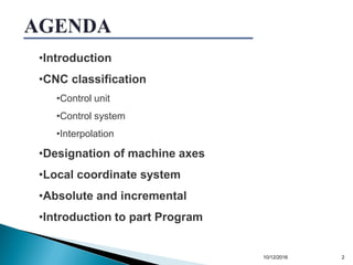
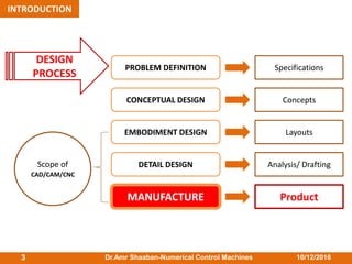
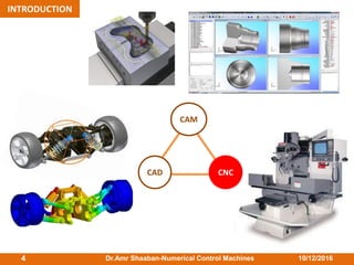
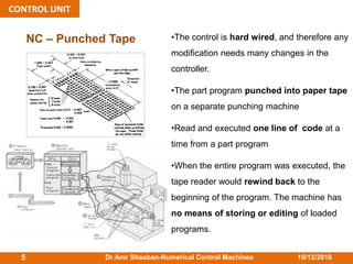
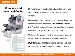
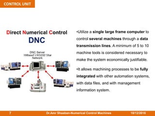
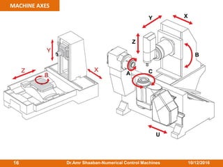
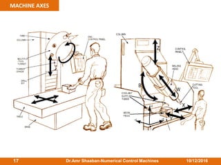
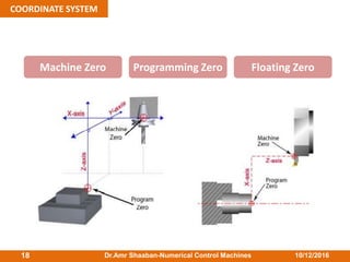
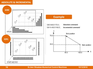
This document provides an overview of numerical control machines and CNC systems. It discusses the classification and components of CNC systems, including the control unit, control systems, interpolation types, machine axes designations, coordinate systems, and part programming. The control unit section describes NC punched tape, computerized numerical control (CNC), and direct numerical control (DNC) systems. The document also covers open and closed loop control systems, point-to-point (P-type), line (L-type), and contour (C-type) interpolation methods, and absolute and incremental programming.
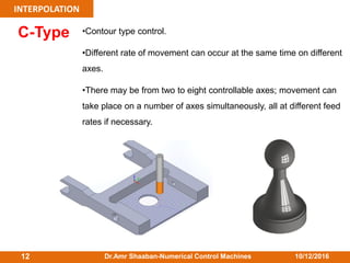


![[Deck] What's New in Spark-Iceberg Integration via DSV2.pptx](https://cdn.slidesharecdn.com/ss_thumbnails/deckwhatsnewinspark-icebergintegrationviadsv2-260210005337-25955b12-thumbnail.jpg?width=640&height=640&fit=bounds)


