Downloaded 1,026 times

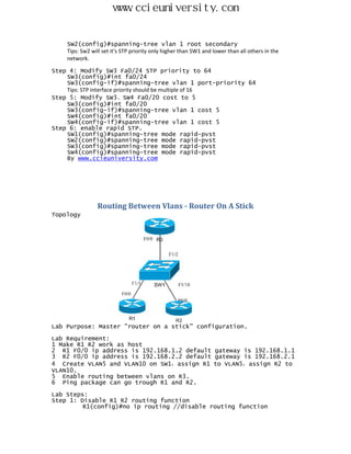
![www.ccieuniversity.com
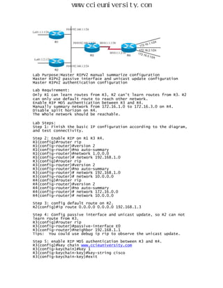
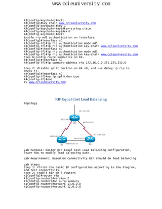
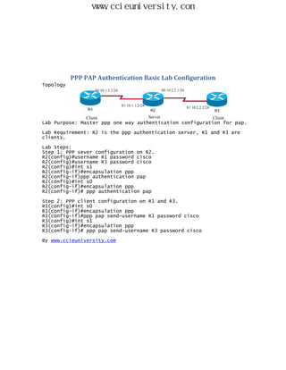
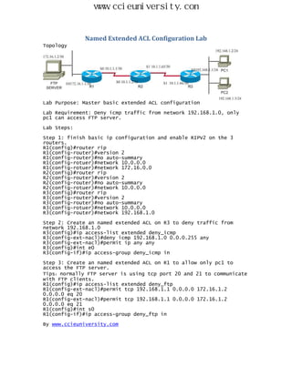
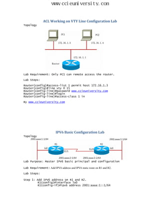
Static Route Configuration
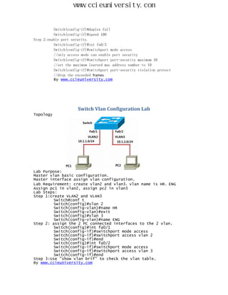
Topology
Lab Purpose: Master static route and default route configuration
Lab Requirement 1: The whole network should be reachable
R1 use egress static route configuration
R2 use next hop interface static route configuration
R2 should perform load balance to network 10.1.1.128/30
R2 should perform load balance to network 10.1.1.128/30
R3 use next hop + egress interface static route configuration
R4 use default route to access other network
Lab Steps:
Step 1 Finish the basic IP configuration according to the diagram,
and test connectivity.
Step 2 Config static route on the 4 routers.
R1(config)#ip route 10.1.1.64 255.255.255.252 s0
R1(config)#ip route 10.1.1.128 255.255.255.252 s0
R2(config)#ip route 10.1.1.128 255.255.255.252 10.1.1.66
R2(config)#ip route 10.1.1.128 255.255.255.252 192.168.1.2
Tips: If you want to enable packet based load balance, You need to
disable Cisco CEF first.
R2(config)#no ip cef
R2(config)#int s1
R2(config-if)#no ip route-cache
R2(config)#int e0
R2(config-if)#no ip route-cache
R3(config)#ip route 10.1.1.0 255.255.255.252 s1 10.1.1.65
R4(config)#ip route 0.0.0.0 0.0.0.0 10.1.1.129
Lab Requirement 2: Change load balance to floating static route on
R2, packets should prefer ethernet to serial line, when ethernet is
down, route should switch to serial line automatically.
Lab Steps: Change the Administrative Distance of static route to
enable the function of floating static route.
R2(config)#no ip route 10.1.1.128 255.255.255.252 10.1.1.66
R2(config)#ip route 10.1.1.128 255.255.255.252 10.1.1.66 2
Before we shutdown E0 interface on R2, ethernet is preferred.
S 10.1.1.128 [1/0] via 192.168.1.2
After we shutdown E0 interface on R2, the route switch to use serial
line.
S 10.1.1.128 [2/0] via 10.1.1.66
By www.ccieuniversity.com](https://image.slidesharecdn.com/ccnalabguide-130323152056-phpapp01/85/CCNA-Lab-Guide-2-320.jpg)
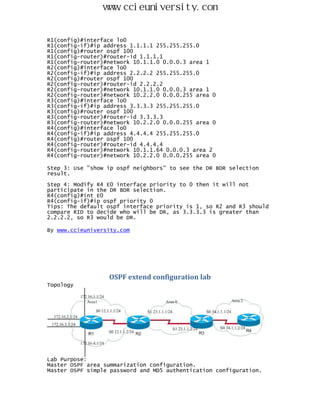
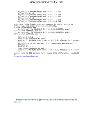

The document describes configuration labs for various routing protocols and technologies: - It includes labs for static route configuration, RIP v1/v2, EIGRP, OSPF, route redistribution, switch configuration, VLANs, VTP, STP, and routing between VLANs. - Frame relay labs cover basic configuration, static maps, routing protocols in Frame Relay networks, point-to-point and multi-point subinterfaces. - Other labs cover PPP authentication, NAT, ACLs, IPv6, and more. The labs provide instructions to configure the protocols and verify their operation in sample network topologies.


