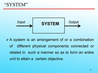
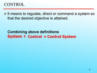
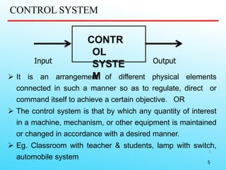
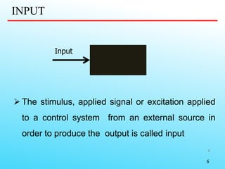
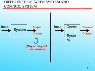
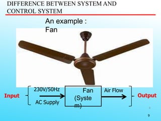
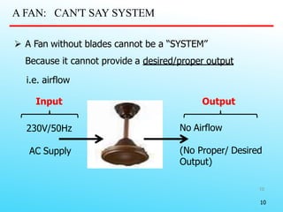
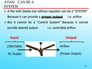
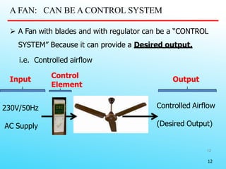
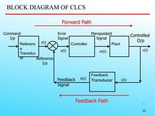
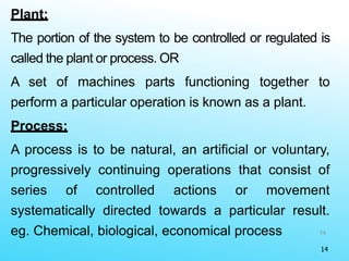
SVERI’s College of Engineering, Pandharpur
Department of Electrical Engineering
Control Systems-I
Dr. Dipti A. Tamboli
HoD, Electrical Engg. Department
2
Unit 1- Introduction to Control systems
Control System – Definition and Practical
Examples
Definition, basic components & classification of
general control system,
Open loop & Close Loop control systems,
Advantages & disadvantages, examples,
Positive & negative feedback,
Transfer Function of open loop and closed loop
control system.
Content
“SYSTEM”
 A system is an arrangement of or a combination
of different physical components connected or
related in such a manner so as to form an entire
unit to attain a certain objective.
SYSTEMInput Output
3
CONTROL
 It means to regulate, direct or command a system so
that the desired objective is attained.
Combining above definitions
System + Control = Control System
4
CONTROL SYSTEM
5
 It is an arrangement of different physical elements
connected in such a manner so as to regulate, direct or
command itself to achieve a certain objective. OR
 The control system is that by which any quantity of interest
in a machine, mechanism, or other equipment is maintained
or changed in accordance with a desired manner.
 Eg. Classroom with teacher & students, lamp with switch,
automobile system
CONTR
OL
SYSTE
M
Input Output
5
INPUT
6
 The stimulus, applied signal or excitation applied
to a control system from an external source in
order to produce the output is called input
Input
6
OUTPUT
7
 The actual response obtained from a system
is called output.
OutputInput
7
DIFFERENCE BETWEEN SYSTEM AND
CONTROL SYSTEM
8
System
Input Contro
l
Syste
m
Input Desired
Output
Proper
Output
(May or may not
be desired)
8
DIFFERENCE BETWEEN SYSTEM AND
CONTROL SYSTEM
9
An example :
Fan
Fan
(Syste
m)
230V/50Hz
AC Supply
Air Flow
Input Output
9
A FAN: CAN'T SAY SYSTEM
10
230V/50Hz
AC Supply
No Airflow
(No Proper/ Desired
Output)
 A Fan without blades cannot be a “SYSTEM”
Because it cannot provide a desired/proper output
i.e. airflow
Input Output
10
A FAN: CAN BE A
SYSTEM
11
 A Fan with blades but without regulator can be a “SYSTEM”
Because it can provide a proper output i.e. airflow
 But it cannot be a “Control System” Because it cannot
provide desired output i.e. controlled airflow
Input Output
230V/50Hz
AC Supply
Airflow
(Proper Output)
11
A FAN: CAN BE A CONTROL SYSTEM
12
 A Fan with blades and with regulator can be a “CONTROL
SYSTEM” Because it can provide a Desired output.
i.e. Controlled airflow
230V/50Hz
AC Supply
Controlled Airflow
(Desired Output)
Input Output
Control
Element
12
BLOCK DIAGRAM OF CLCS
13
Referenc
e
Transduc
er
Controller Plant
Feedback
Transducer
Command
I/p
Reference
I/p
Feedback
Signal
Manipulated
Signal
Error
Signal
Controlled
O/pr(t)
e(t)
b(t) c(t)
c(t)m(t)
Forward Path
Feedback Path
13
14
Plant:
The portion of the system to be controlled or regulated is
called the plant or process. OR
A set of machines parts functioning together to
perform a particular operation is known as a plant.
Process:
A process is to be natural, an artificial or voluntary,
progressively continuing operations that consist of
series of controlled actions or movement
systematically directed towards a particular result.
eg. Chemical, biological, economical process
14
15
Controller:
The element of the system itself or external to the system
which control the plant or process is called controller.
Disturbance:
Disturbance is a signal which tends to adversely
affect the value of the output of a syste. If such
disturbance is generated within the system itself, it is
called internal disturbance. If disturbance generated
outside the system acting as an extra input to the
system in addition to its normal input, then it is called
as external disturbance.
15
16
Feedback control:
Feedback control is an operation which, in the
presence of disturbances, tend to reduce the
difference between output of the system and the
reference input. Only unpredictable disturbances are
to be designed, since for predictable/known
disturbances, it is always possible to include
compensation within the system, so that measurement
is not necessary. Thus,
A feedback control system is one which tend to
maintain a prescribed relationship between the output
and the reference input by comparing these and using16
17
Thank You

L2 unit 1-definition and practical examples, basic clcs

  • 1.
    SVERI’s College ofEngineering, Pandharpur Department of Electrical Engineering Control Systems-I Dr. Dipti A. Tamboli HoD, Electrical Engg. Department
  • 2.
    2 Unit 1- Introductionto Control systems Control System – Definition and Practical Examples Definition, basic components & classification of general control system, Open loop & Close Loop control systems, Advantages & disadvantages, examples, Positive & negative feedback, Transfer Function of open loop and closed loop control system. Content
  • 3.
    “SYSTEM”  A systemis an arrangement of or a combination of different physical components connected or related in such a manner so as to form an entire unit to attain a certain objective. SYSTEMInput Output 3
  • 4.
    CONTROL  It meansto regulate, direct or command a system so that the desired objective is attained. Combining above definitions System + Control = Control System 4
  • 5.
    CONTROL SYSTEM 5  Itis an arrangement of different physical elements connected in such a manner so as to regulate, direct or command itself to achieve a certain objective. OR  The control system is that by which any quantity of interest in a machine, mechanism, or other equipment is maintained or changed in accordance with a desired manner.  Eg. Classroom with teacher & students, lamp with switch, automobile system CONTR OL SYSTE M Input Output 5
  • 6.
    INPUT 6  The stimulus,applied signal or excitation applied to a control system from an external source in order to produce the output is called input Input 6
  • 7.
    OUTPUT 7  The actualresponse obtained from a system is called output. OutputInput 7
  • 8.
    DIFFERENCE BETWEEN SYSTEMAND CONTROL SYSTEM 8 System Input Contro l Syste m Input Desired Output Proper Output (May or may not be desired) 8
  • 9.
    DIFFERENCE BETWEEN SYSTEMAND CONTROL SYSTEM 9 An example : Fan Fan (Syste m) 230V/50Hz AC Supply Air Flow Input Output 9
  • 10.
    A FAN: CAN'TSAY SYSTEM 10 230V/50Hz AC Supply No Airflow (No Proper/ Desired Output)  A Fan without blades cannot be a “SYSTEM” Because it cannot provide a desired/proper output i.e. airflow Input Output 10
  • 11.
    A FAN: CANBE A SYSTEM 11  A Fan with blades but without regulator can be a “SYSTEM” Because it can provide a proper output i.e. airflow  But it cannot be a “Control System” Because it cannot provide desired output i.e. controlled airflow Input Output 230V/50Hz AC Supply Airflow (Proper Output) 11
  • 12.
    A FAN: CANBE A CONTROL SYSTEM 12  A Fan with blades and with regulator can be a “CONTROL SYSTEM” Because it can provide a Desired output. i.e. Controlled airflow 230V/50Hz AC Supply Controlled Airflow (Desired Output) Input Output Control Element 12
  • 13.
    BLOCK DIAGRAM OFCLCS 13 Referenc e Transduc er Controller Plant Feedback Transducer Command I/p Reference I/p Feedback Signal Manipulated Signal Error Signal Controlled O/pr(t) e(t) b(t) c(t) c(t)m(t) Forward Path Feedback Path 13
  • 14.
    14 Plant: The portion ofthe system to be controlled or regulated is called the plant or process. OR A set of machines parts functioning together to perform a particular operation is known as a plant. Process: A process is to be natural, an artificial or voluntary, progressively continuing operations that consist of series of controlled actions or movement systematically directed towards a particular result. eg. Chemical, biological, economical process 14
  • 15.
    15 Controller: The element ofthe system itself or external to the system which control the plant or process is called controller. Disturbance: Disturbance is a signal which tends to adversely affect the value of the output of a syste. If such disturbance is generated within the system itself, it is called internal disturbance. If disturbance generated outside the system acting as an extra input to the system in addition to its normal input, then it is called as external disturbance. 15
  • 16.
    16 Feedback control: Feedback controlis an operation which, in the presence of disturbances, tend to reduce the difference between output of the system and the reference input. Only unpredictable disturbances are to be designed, since for predictable/known disturbances, it is always possible to include compensation within the system, so that measurement is not necessary. Thus, A feedback control system is one which tend to maintain a prescribed relationship between the output and the reference input by comparing these and using16
  • 17.