Downloaded 35 times
![Previous Chapter 1 Index Next
Section 1.3: Historical Periods of Control Theory is covered by slides: 5, [6], 7, 8, 9, 10
Home](https://image.slidesharecdn.com/chapter1-automaticcontroloverview-101107143337-phpapp02/85/Chapter-1-Automatic-Controloverview-1-320.jpg)
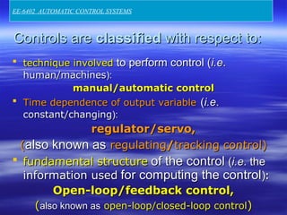
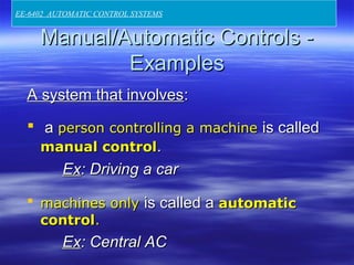
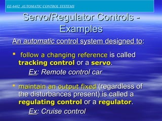
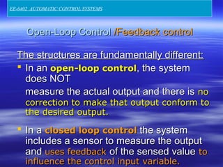
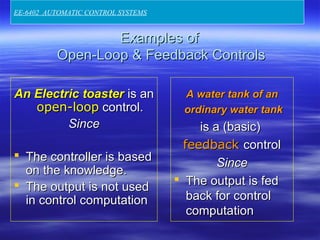
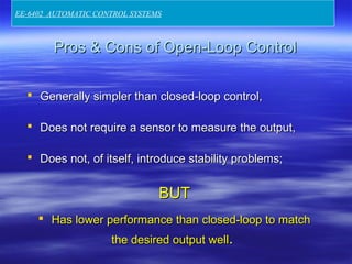
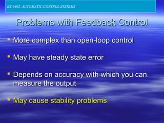
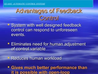
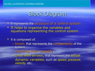
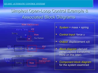
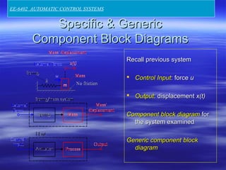
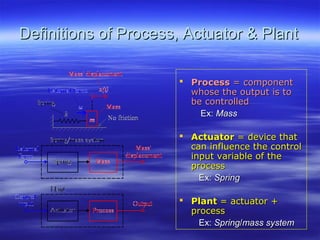
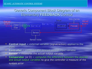
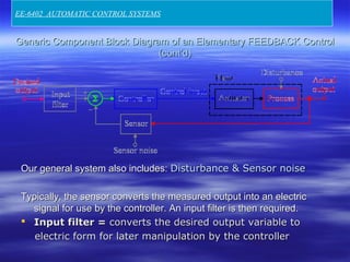
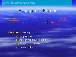
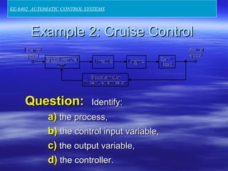
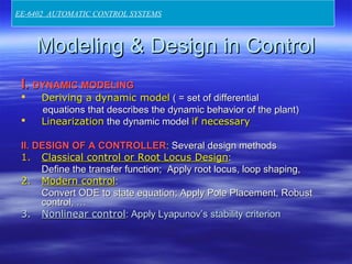
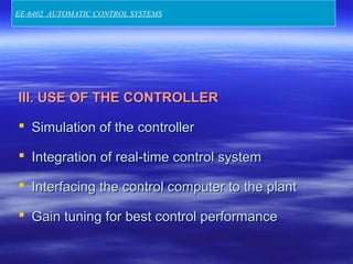
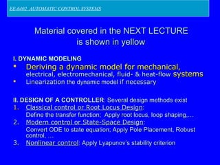

The document provides an overview of control theory, defining key terms such as control, process, actuator, and plant, and classifying controls based on technique, time dependence, and structure. It distinguishes between open-loop and feedback control systems, highlighting their respective advantages and disadvantages, and includes examples of each type. Additionally, it details the modeling and design processes in control systems, focusing on different control strategies and simulation methods.


![Chinua Achebe - Things Fall Apart [Edited Version]](https://cdn.slidesharecdn.com/ss_thumbnails/chinuaachebe-thingsfallapart2-130806172255-phpapp02-thumbnail.jpg?width=640&height=640&fit=bounds)


