Downloaded 72 times


![96
0856I–AVR–07/10
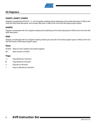
AVR Instruction Set
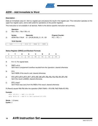
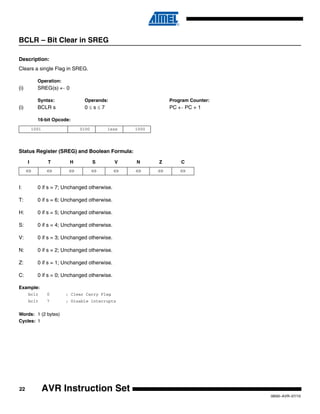
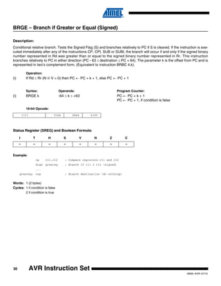
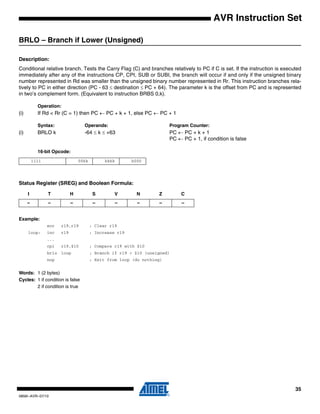
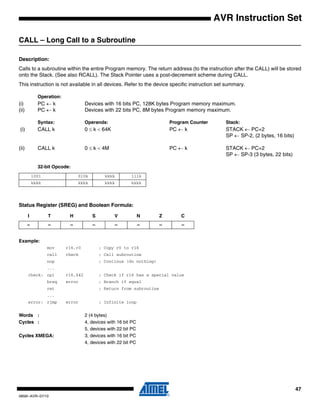
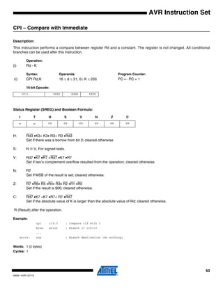
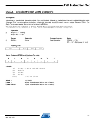
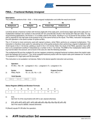
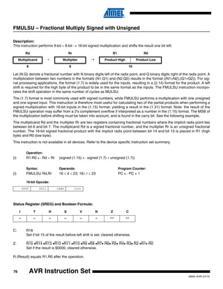
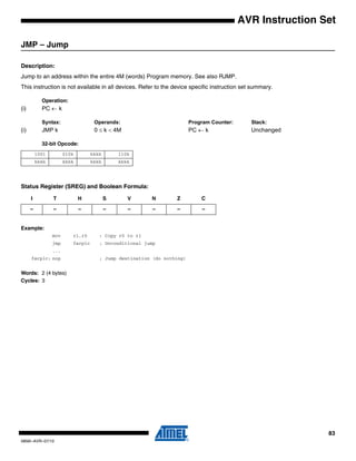
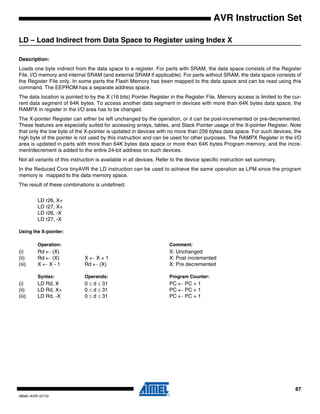
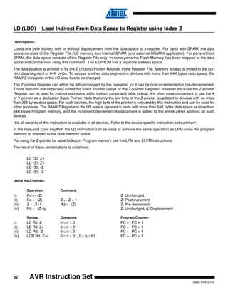
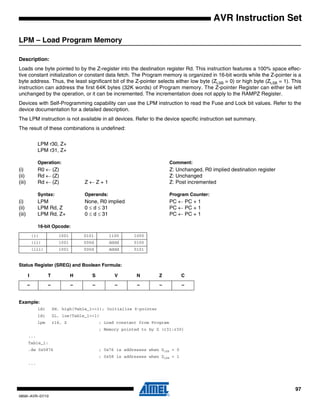
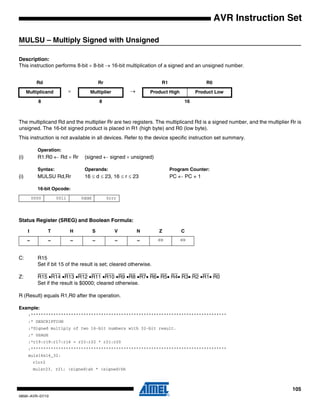
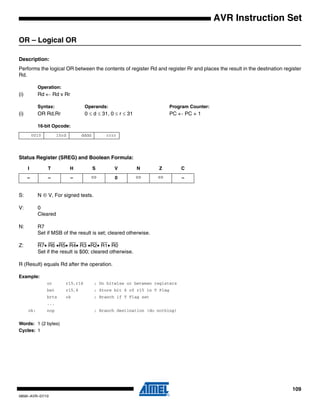
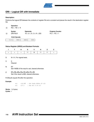
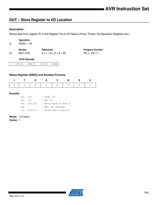
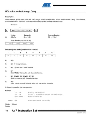
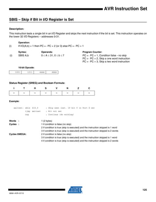
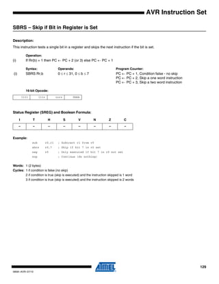
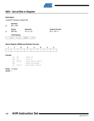
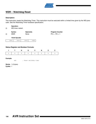
LDS (16-bit) – Load Direct from Data Space
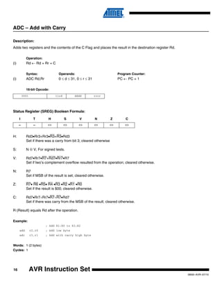
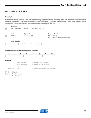
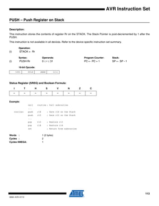
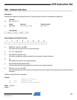
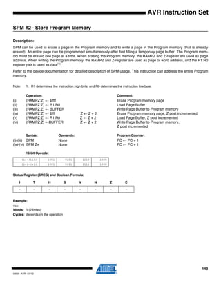
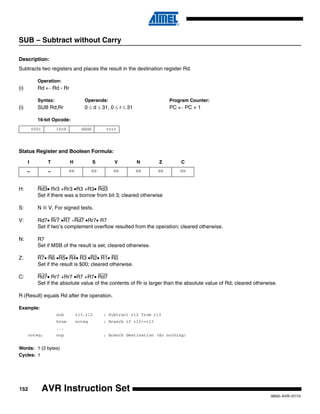
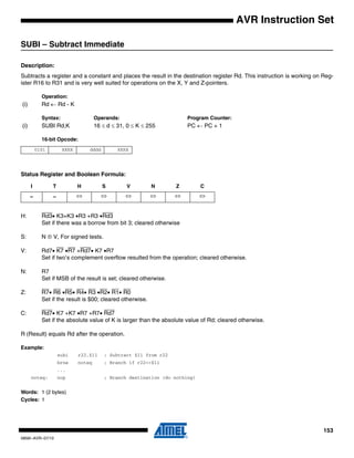
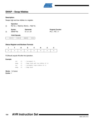
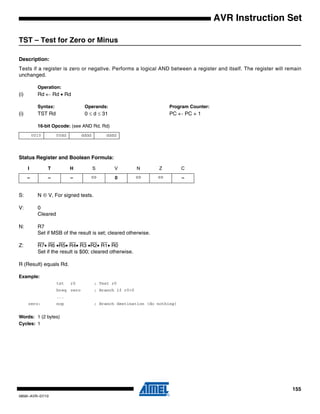
Description:
Loads one byte from the data space to a register. For parts with SRAM, the data space consists of the Register File, I/O
memory and internal SRAM (and external SRAM if applicable). For parts without SRAM, the data space consists of the reg-
ister file only. In some parts the Flash memory has been mapped to the data space and can be read using this command.
The EEPROM has a separate address space.
A 7-bit address must be supplied. The address given in the instruction is coded to a data space address as follows:
ADDR[7:0] = (INST[8], INST[8], INST[10], INST[9], INST[3], INST[2], INST[1], INST[0])
Memory access is limited to the address range 0x40..0xbf.
This instruction is not available in all devices. Refer to the device specific instruction set summary.
Operation:
(i) Rd ← (k)
Syntax: Operands: Program Counter:
(i) LDS Rd,k 16 ≤ d ≤ 31, 0 ≤ k ≤ 127 PC ← PC + 1
16-bit Opcode:
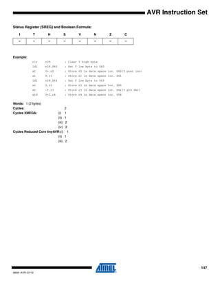
Status Register (SREG) and Boolean Formula:
Example:
lds r16,$00 ; Load r16 with the contents of data space location $00
add r16,r17 ; add r17 to r16
sts $00,r16 ; Write result to the same address it was fetched from
Words: 1 (2 bytes)
Cycles: 1
Note: Registers r0..r15 are remapped to r16..r31.
1010 0kkk dddd kkkk
I T H S V N Z C
– – – – – – – –](https://image.slidesharecdn.com/avrinstructionset-140407125446-phpapp02/85/Avr-instruction-set-96-320.jpg)


![151
0856I–AVR–07/10
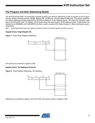
AVR Instruction Set
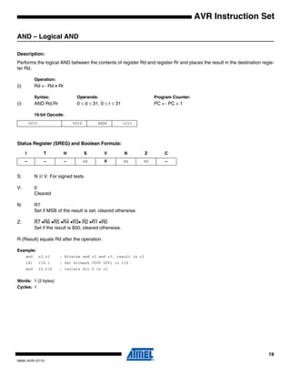
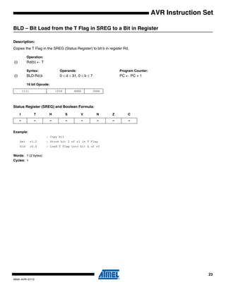
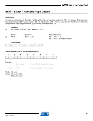
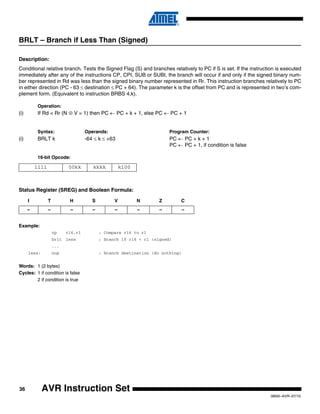
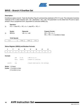
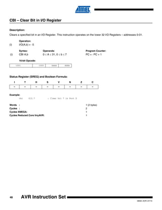
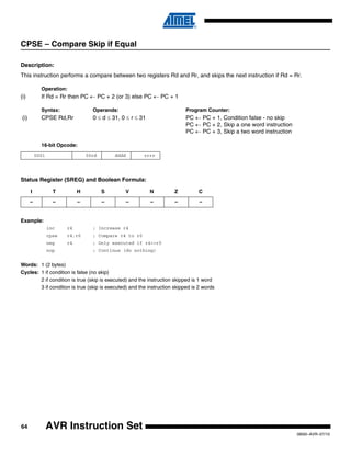
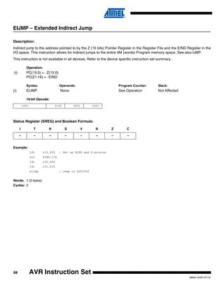
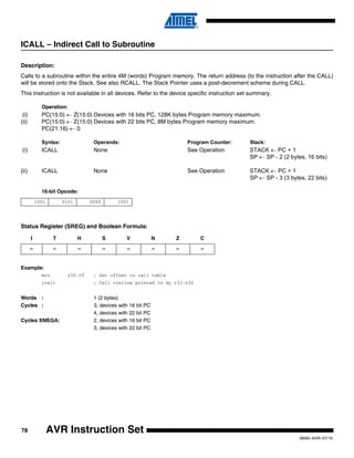
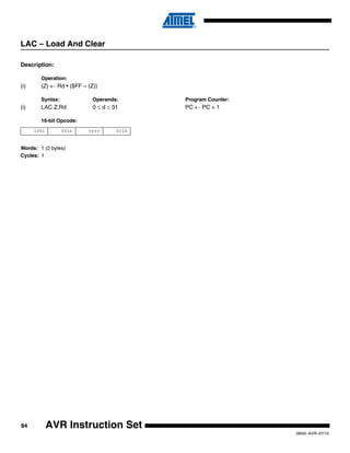
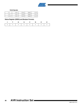
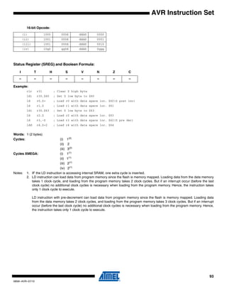
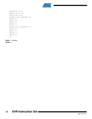
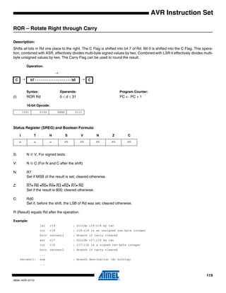
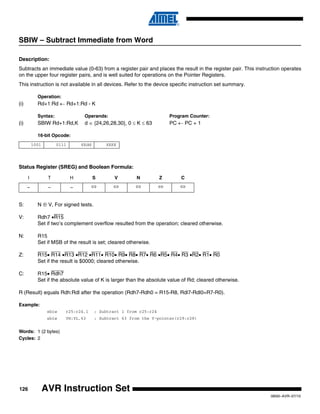
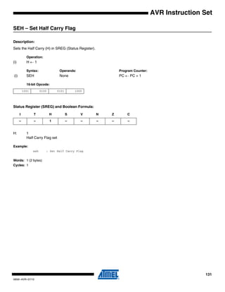
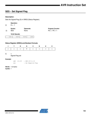
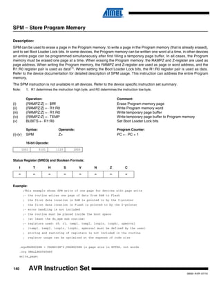
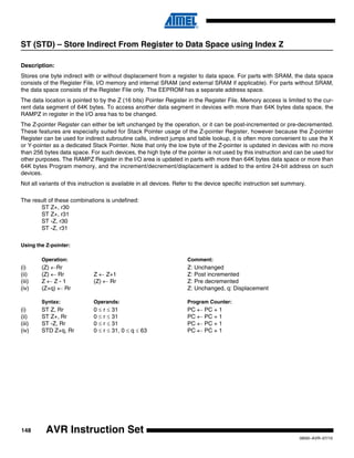
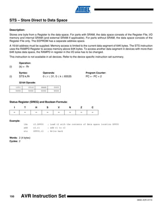
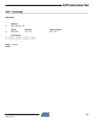
STS (16-bit) – Store Direct to Data Space
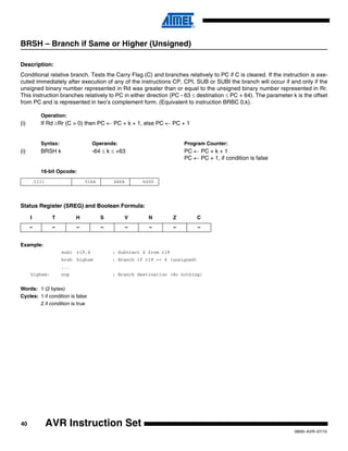
Description:
Stores one byte from a Register to the data space. For parts with SRAM, the data space consists of the Register File, I/O
memory and internal SRAM (and external SRAM if applicable). For parts without SRAM, the data space consists of the
Register File only. In some parts the Flash memory has been mapped to the data space and can be written using this com-
mand. The EEPROM has a separate address space.
A 7-bit address must be supplied. The address given in the instruction is coded to a data space address as follows:
ADDR[7:0] = (INST[8], INST[8], INST[10], INST[9], INST[3], INST[2], INST[1], INST[0] )
Memory access is limited to the address range 0x40...0xbf of the data segment.
This instruction is not available in all devices. Refer to the device specific instruction set summary.
Operation:
(i) (k) ← Rr
Syntax: Operands: Program Counter:
(i) STS k,Rr 16 ≤ r ≤ 31, 0 ≤ k ≤ 127 PC ← PC + 1
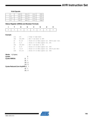
16-bit Opcode:
Status Register (SREG) and Boolean Formula:
Example:
lds r16,$00 ; Load r16 with the contents of data space location $00
add r16,r17 ; add r17 to r16
sts $00,r16 ; Write result to the same address it was fetched from
Words: 1 (2 bytes)
Cycles: 1
Note: Registers r0..r15 are remaped to r16..r31
1010 1kkk dddd kkkk
I T H S V N Z C
– – – – – – – –](https://image.slidesharecdn.com/avrinstructionset-140407125446-phpapp02/85/Avr-instruction-set-151-320.jpg)

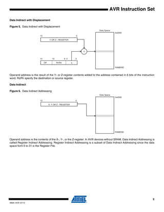
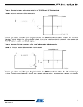
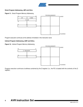
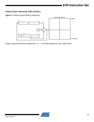
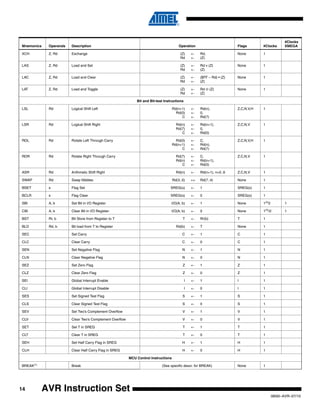
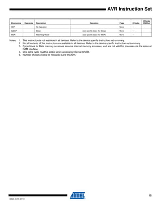
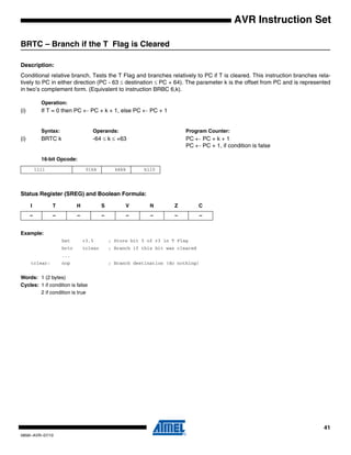
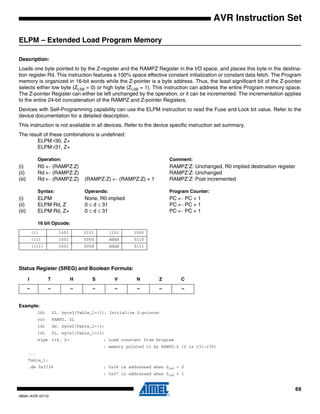
The document provides information about the instruction set nomenclature, registers, operands, status register flags, program and data addressing modes, and the complete instruction set of the AVR microcontroller architecture. It defines the purpose and bit mappings of registers like SREG, RAMPX, RAMPY, RAMPZ, and EIND. It also describes the various addressing modes for accessing program memory and data memory, including register direct, I/O direct, data direct, indirect with/without displacement, and indirect with pre/post-increment. The complete instruction set summary provides the mnemonics, operands, description, operation on flags and clock cycles for arithmetic, logic, branch, and other instructions.


![[ASM]Lab4](https://cdn.slidesharecdn.com/ss_thumbnails/asmlab4-151121101809-lva1-app6891-thumbnail.jpg?width=640&height=640&fit=bounds)


