Download to read offline


![INTERFACING WITH AND LCD
In this process it describes the operation modes of LCDs and also how to program and
interface LCD to PC via 8255 (also known as the Intel 8255 (or i8255)
Programmable Peripheral Interface(PPI) chip is a peripheral chip originally developed for
the Intel 8085 microprocessor,[1] and as such is a member of a large array of such chips, known
as the MCS-85 Family.)
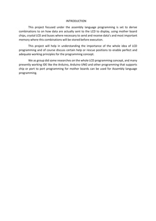
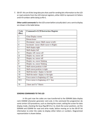
As described in the image below is the pin description for LCD
Pin Description and Function
1. VSS: this is the ground power connection also known as the negative –ve power
supply.
2. VCC: this is now the positive +ve connection for power that bring in a power supply of
+5V.
3. VEE: this as described in the diagram above is used to control the LCD contrast in
respect to the incoming power supply.
4. RS: this are now linked with the registers for information storing, so from the diagram
when RS=0 the option for command register is prompted to call all commands from
the registers but when the RS=1 the data register is set to accept data storage.
5. R/W: this is used for read and write into the registers or address or storage, when
R/W= 0 it is set to write only into the destination, but when R/W=1 it is set to read
from the destination.
6. E: often regarded as the Enable, this pin is used to as a circuit used to store information
presented by from the data pins, when data are sent , a high to low pulse must be applied
is applied to this pin, this pulse must be around 450 ns wide.](https://image.slidesharecdn.com/alplcd-140529104212-phpapp01/85/Alp-lcd-4-320.jpg)


This document describes a project to send data to an LCD display using assembly language programming. It discusses interfacing with an LCD via an 8255 chip and sending commands to set up the LCD. Code examples are provided to initialize the LCD, write commands and data, and display text. While manual programming takes time, understanding LCD interfacing helps with easy display design and addressing. The document concludes that this provides a useful tool for LCD screen programming.