This document describes the design and implementation of an embedded control system for orienting a radar antenna. The system uses a field programmable gate array (FPGA) to process input from a radar's plane position indicator (PPI) display and control a stepper motor that adjusts the antenna's azimuth position. When a target blip appears on the PPI, the FPGA commands the stepper motor to rotate clockwise or counterclockwise as needed to align the antenna to geographic north. Experimental results showed the system could successfully orient the antenna to within 0.18 degrees using the FPGA and stepper motor control approach.
SATELLITE DISH POSITIONING CONTROL BY DC MOTOR USING IR REMOTE CONTROL IAEME Publication
In this paper, PIC microcontroller was designed to develop a satellite dish positioning system which can be operated by using a remote control. The main point of using a dish is to receive signal from satellites and other broadcasting sources. In order to get the exact angle of position of the dish, it needs to be adjusted manually. In order to overcome the difficulty of adjusting manually, this paper helps in adjusting the position of the dish through a remote control. Remote control acts as a transmitter whose data is received by an IR receiver which is interfaced to a microcontroller of PIC 16F877A. The remote control sends coded data to the receiver whose output is then sent to the microcontroller.
This paper focuses on the development of a prototype of thruster motor speed controller which exhibits robust performance for an Autonomous underwater vehicle. H infinity based speed controller with particle swarm optimized weights for a sensorless BLDC motor which is used as electrical thruster has been simulated in MATLAB/ SIMULINK and implemented using TI C2000 Delfino LaunchPad LaunchXL-F28377S and BoostXL DRV 8301. A performance comparison in reference tracking has been done with conventional PI controller and experimental results have been discussed in detail. The percentage variation in speed with respect to reference speed of proposed strategy has been observed to be 0.65% whereas it is 1.1% with PI controller. It has also been found that the proposed control strategy exhibits smooth starting with better reference tracking and less torque ripples.
ArduinoBased Head GestureControlled Robot UsingWireless CommunicationIJERA Editor
This paper describes the robustness of ardiuno based head movement controlled robot. This robot is controlled using motion sensor which is mounted on the head. In future there is need of robots which can be used to ease the human tasks and interact with the human easily. Our objective is to control the robot using head gesture. Accelerometer is used to detect the direction of head movement. In order to full-fill our requirement a program has been written and executed using a microcontroller system. By observing the results of experimentation our gesture formula is very competent and it’s also enhance the natural way of intelligence and also assembled in a simple hardware circuit.
IOT based project for accident victims,where the message is directly sent to the nearby ambulance, and the traffic is maintained on the basis of the fact that whether an ambulance is present on the road or not.
International Journal of Computational Engineering Research(IJCER)ijceronline
International Journal of Computational Engineering Research(IJCER) is an intentional online Journal in English monthly publishing journal. This Journal publish original research work that contributes significantly to further the scientific knowledge in engineering and Technology
Antenna Azimuth Position Control System using PIDController & State-Feedback ...IJECEIAES
This paper analyzed two controllers with the view to improve the overall control of an antenna azimuth position. Frequency ranges were utilized for the PID controller in the system; while Ziegler-Nichols was used to tune the PID parameter gains. A state feedback controller was formulated from the state-space equation and pole-placements were adopted to ensure the model design complied with the specifications to meet transient response. MATLAB Simulink platform was used for the system simulation. The system response for both the two controllers were analyzed and compared to ascertain the best controller with best azimuth positioning for the antenna. It was observed that state-feedback controller provided the best azimuth positioning control with a little settling time, some value of overshoot and no steady-state error is detected.
The following resources come from the 2009/10 BEng in Digital Systems and Computer Engineering (course number 2ELE0065) from the University of Hertfordshire. All the mini projects are designed as level two modules of the undergraduate programmes.
The objectives of this project are to design, develop and test software for an embedded system that will smoothly control the rotation of a stepper motor, taking into account the physical constraints on the maximum operating speed of the motor.
Each student will be required to design a ‘C’ program can rotate a stepper motor to a number of user-defined positions as quickly as possible. This will include sensing of the marker pulse, the implementation of an appropriate speed profile and the use of timer-generated interrupts.
Controlled Rotation of the Shaft of a Stepper Motor with 8051 Microcontrollerinventionjournals
With a view to control the direction, speed and angle of rotation of the shaft of a stepper motor, the stepper motor was interfaced with 8051 microcontroller through 8255 PPI ports and rotating the shaft by supplying the required data by executing 8051 assembly language programs. The Hexadecimal data 07, 0B, 0D and 0E was given as inputs of stepper motor to rotate the shaft in a clock wise direction, while 07, 0E, 0D and 0B was given to the amplifiers produce opposite magnetic poles to rotate the shaft of a stepper motor in an anti clock wise direction. The speed was controlled by setting different values of the registers used in the delay subroutine. The lesser values of delay registers will increase the speed of the shaft of the stepper motor. To rotate the shaft of a stepper motor with a specified angle, a separate register was used to supply the above datas for required times to produce the suitable angle. An effort were made to rotate the shaft of the motor in both clock wise and anti clock wise alternatively with a specific angle by combining the assembly language programs of both clock wise and anti clock wise rotations at one place with appropriate count value.
Power optimisation scheme of induction motor using FLC for electric vehicleAsoka Technologies
In electric vehicles (EVs) and hybrid EVs, energy efficiency is essential where the energy storage is limited. Adding to its high stability and low cost, the induction motor efficiency improves with loss minimisation. Also, it can consume more power than the actual need to perform its working when it is operating in less than full load condition. This study proposes a control strategy based on the fuzzy logic control (FLC) for EV applications. FLC controller can improve the starting current amplitude and saves more power. Through the MATLAB/SIMULINK software package, the performance of this control was verified through simulation. As compared with the conventional proportional integral derivative controller, the simulation schemes show good, high-performance results in time-domain response and rapid rejection of system-affected disturbance. Therefore, the core losses of the induction motor are greatly reduced, and in this way improves the efficiency of the driving system. Finally, the suggested control system is validated by the experimental results obtained in the authors’ laboratory, which are in good agreement with the simulation results.
Traffic density dependent taffic light controller pdf NAVODITA KUMARI
By using this system configuration we can reduce the possibilities of traffic jams caused by traffic lights to an extent. The number of passing vehicles on the road decides the density range of traffics and on the basis of vehicle count microcontroller decides the traffic light delays.
Network Lifetime Analysis of Routing Protocols of Short Network in QualnetIOSR Journals
Abstract: A Mobile Ad-Hoc Network (MANET) is a collection of wireless mobile nodes that communicates with each other without using any existing infrastructure, access point or centralized administration. Mobile ad-hoc network have the attributes such as wireless connection, continuously changing topology, distributed operation and ease of deployment. In this paper we have compared the energy consumption of reactive, proactive & hybrid routing protocol AODV,DSR,RIP & ZRP by using different mobility model. We have analyzed the Network lifetime of protocols by varying pay load, mobility, pause time and type of traffic (CBR). A detailed simulation has been carried out in qualnet. The metrics used for performance analysis are energy consumed & battery consumption. It has been observed that RIP has better network lifetime than other.
Filtering Unwanted Messages from Online Social Networks (OSN) using Rule Base...IOSR Journals
Online Social Networks (OSNs) are today one of the most popular interactive medium to share,
communicate, and distribute a significant amount of human life information. In OSNs, information filtering can
also be used for a different, more responsive, function. This is owing to the fact that in OSNs there is the
possibility of posting or commenting other posts on particular public/private regions, called in general walls.
Information filtering can therefore be used to give users the ability to automatically control the messages
written on their own walls, by filtering out unwanted messages. OSNs provide very little support to prevent
unwanted messages on user walls. For instance, Facebook permits users to state who is allowed to insert
messages in their walls (i.e., friends, defined groups of friends or friends of friends). Though, no content-based
partialities are preserved and therefore it is not possible to prevent undesired communications, for instance
political or offensive ones, no matter of the user who posts them. To propose and experimentally evaluate an
automated system, called Filtered Wall (FW), able to filter unwanted messages from OSN user walls
Design and Implementation of Payload Camera Control System for Unmanned Aeria...ijtsrd
The aim of this research is to design and implement PIC based radio frequency wireless communication system of two axes Pan Tilt payload camera unit for UAV. Camera is used as a payload and two servo motors are used to adjust the camera positioner in two axes to take the desired photo. User interface program is designed by C language on personal computer and serial communication RS232 protocol is used for data communication between personal computer and microcontroller. SONY digital camera is used to take the desired photographs and store recorded data to its memory. Ultra High Frequency band radio frequency wireless transmitter and receiver pairs are used for data communication link between the ground station and the receiver on the vehicle. And they are Amplitude Shift Keying ASK type IC and transmission frequency is 433.92MHZ. The Futaba S3003 servo motors mounted on the payload are driven by PWM pulse related to the transmitted data from the transmitter in order to get the desire payload camera orientation. The control system is based on microcontroller PIC16F877A. The microcontroller CCS C language is used for this control system. Saw Aung Nyein Oo | Naw Octavia "Design and Implementation of Payload (Camera) Control System for Unmanned Aerial Vehicle" Published in International Journal of Trend in Scientific Research and Development (ijtsrd), ISSN: 2456-6470, Volume-3 | Issue-5 , August 2019, URL: https://www.ijtsrd.com/papers/ijtsrd26781.pdf Paper URL: https://www.ijtsrd.com/engineering/electronics-and-communication-engineering/26781/design-and-implementation-of-payload-camera-control-system-for-unmanned-aerial-vehicle/saw-aung-nyein-oo
Sigma-Delta Analog-to-Digital converter (ADC), is widely used in portable electronic products. An operational
transconductance amplifier (OTA) is one of the most important components of ADC. This paper presents a
new design of two stages OTA. The design incorporates Sleep insertion technique and leakage feedback current
approach for improving design parameters such as gain, and power as compared to earlier work. The design is
simulated in 0.18µm CMOS technology with supply voltage 1.8V.
IJERA (International journal of Engineering Research and Applications) is International online, ... peer reviewed journal. For more detail or submit your article, please visit www.ijera.com
FPGA based synchronous multi-channel PWM generator for humanoid robot IJECEIAES
In this paper, synchronous multi-channel pulse width modulation (PWM) generator for driving servo motors of humanoid robot was proposed. In an application, the humanoid robot requires smooth and beautiful movement, therefore the PWM signal for each servo motor must be synchronized. Since microcontroller (slave) has no enough channels to generate synchronous PWMs for 32 servo motors, field programmable gate array (FPGA) was used as slave for the humanoid robot. The FPGA was controlled by microcontroller (master) using serial communication. Simulation results show the system can perform serial communication, synchronize, and convert data well. The system can also generate PWM simultaneously with accurate duty cycle and fix period of 20ms.
International Journal of Engineering Research and Applications (IJERA) is an open access online peer reviewed international journal that publishes research and review articles in the fields of Computer Science, Neural Networks, Electrical Engineering, Software Engineering, Information Technology, Mechanical Engineering, Chemical Engineering, Plastic Engineering, Food Technology, Textile Engineering, Nano Technology & science, Power Electronics, Electronics & Communication Engineering, Computational mathematics, Image processing, Civil Engineering, Structural Engineering, Environmental Engineering, VLSI Testing & Low Power VLSI Design etc.
Securing your Kubernetes cluster_ a step-by-step guide to success !KatiaHIMEUR1
Today, after several years of existence, an extremely active community and an ultra-dynamic ecosystem, Kubernetes has established itself as the de facto standard in container orchestration. Thanks to a wide range of managed services, it has never been so easy to set up a ready-to-use Kubernetes cluster.
However, this ease of use means that the subject of security in Kubernetes is often left for later, or even neglected. This exposes companies to significant risks.
In this talk, I'll show you step-by-step how to secure your Kubernetes cluster for greater peace of mind and reliability.
Accelerate your Kubernetes clusters with Varnish CachingThijs Feryn
A presentation about the usage and availability of Varnish on Kubernetes. This talk explores the capabilities of Varnish caching and shows how to use the Varnish Helm chart to deploy it to Kubernetes.
This presentation was delivered at K8SUG Singapore. See https://feryn.eu/presentations/accelerate-your-kubernetes-clusters-with-varnish-caching-k8sug-singapore-28-2024 for more details.
UiPath Test Automation using UiPath Test Suite series, part 4DianaGray10
Welcome to UiPath Test Automation using UiPath Test Suite series part 4. In this session, we will cover Test Manager overview along with SAP heatmap.
The UiPath Test Manager overview with SAP heatmap webinar offers a concise yet comprehensive exploration of the role of a Test Manager within SAP environments, coupled with the utilization of heatmaps for effective testing strategies.
Participants will gain insights into the responsibilities, challenges, and best practices associated with test management in SAP projects. Additionally, the webinar delves into the significance of heatmaps as a visual aid for identifying testing priorities, areas of risk, and resource allocation within SAP landscapes. Through this session, attendees can expect to enhance their understanding of test management principles while learning practical approaches to optimize testing processes in SAP environments using heatmap visualization techniques
What will you get from this session?
1. Insights into SAP testing best practices
2. Heatmap utilization for testing
3. Optimization of testing processes
4. Demo
Topics covered:
Execution from the test manager
Orchestrator execution result
Defect reporting
SAP heatmap example with demo
Speaker:
Deepak Rai, Automation Practice Lead, Boundaryless Group and UiPath MVP
The Art of the Pitch: WordPress Relationships and SalesLaura Byrne
Clients don’t know what they don’t know. What web solutions are right for them? How does WordPress come into the picture? How do you make sure you understand scope and timeline? What do you do if sometime changes?
All these questions and more will be explored as we talk about matching clients’ needs with what your agency offers without pulling teeth or pulling your hair out. Practical tips, and strategies for successful relationship building that leads to closing the deal.
Encryption in Microsoft 365 - ExpertsLive Netherlands 2024Albert Hoitingh
In this session I delve into the encryption technology used in Microsoft 365 and Microsoft Purview. Including the concepts of Customer Key and Double Key Encryption.
GDG Cloud Southlake #33: Boule & Rebala: Effective AppSec in SDLC using Deplo...James Anderson
Effective Application Security in Software Delivery lifecycle using Deployment Firewall and DBOM
The modern software delivery process (or the CI/CD process) includes many tools, distributed teams, open-source code, and cloud platforms. Constant focus on speed to release software to market, along with the traditional slow and manual security checks has caused gaps in continuous security as an important piece in the software supply chain. Today organizations feel more susceptible to external and internal cyber threats due to the vast attack surface in their applications supply chain and the lack of end-to-end governance and risk management.
The software team must secure its software delivery process to avoid vulnerability and security breaches. This needs to be achieved with existing tool chains and without extensive rework of the delivery processes. This talk will present strategies and techniques for providing visibility into the true risk of the existing vulnerabilities, preventing the introduction of security issues in the software, resolving vulnerabilities in production environments quickly, and capturing the deployment bill of materials (DBOM).
Speakers:
Bob Boule
Robert Boule is a technology enthusiast with PASSION for technology and making things work along with a knack for helping others understand how things work. He comes with around 20 years of solution engineering experience in application security, software continuous delivery, and SaaS platforms. He is known for his dynamic presentations in CI/CD and application security integrated in software delivery lifecycle.
Gopinath Rebala
Gopinath Rebala is the CTO of OpsMx, where he has overall responsibility for the machine learning and data processing architectures for Secure Software Delivery. Gopi also has a strong connection with our customers, leading design and architecture for strategic implementations. Gopi is a frequent speaker and well-known leader in continuous delivery and integrating security into software delivery.
Builder.ai Founder Sachin Dev Duggal's Strategic Approach to Create an Innova...Ramesh Iyer
In today's fast-changing business world, Companies that adapt and embrace new ideas often need help to keep up with the competition. However, fostering a culture of innovation takes much work. It takes vision, leadership and willingness to take risks in the right proportion. Sachin Dev Duggal, co-founder of Builder.ai, has perfected the art of this balance, creating a company culture where creativity and growth are nurtured at each stage.
UiPath Test Automation using UiPath Test Suite series, part 3DianaGray10
Welcome to UiPath Test Automation using UiPath Test Suite series part 3. In this session, we will cover desktop automation along with UI automation.
Topics covered:
UI automation Introduction,
UI automation Sample
Desktop automation flow
Pradeep Chinnala, Senior Consultant Automation Developer @WonderBotz and UiPath MVP
Deepak Rai, Automation Practice Lead, Boundaryless Group and UiPath MVP
Slack (or Teams) Automation for Bonterra Impact Management (fka Social Soluti...Jeffrey Haguewood
Sidekick Solutions uses Bonterra Impact Management (fka Social Solutions Apricot) and automation solutions to integrate data for business workflows.
We believe integration and automation are essential to user experience and the promise of efficient work through technology. Automation is the critical ingredient to realizing that full vision. We develop integration products and services for Bonterra Case Management software to support the deployment of automations for a variety of use cases.
This video focuses on the notifications, alerts, and approval requests using Slack for Bonterra Impact Management. The solutions covered in this webinar can also be deployed for Microsoft Teams.
Interested in deploying notification automations for Bonterra Impact Management? Contact us at sales@sidekicksolutionsllc.com to discuss next steps.
Elevating Tactical DDD Patterns Through Object CalisthenicsDorra BARTAGUIZ
After immersing yourself in the blue book and its red counterpart, attending DDD-focused conferences, and applying tactical patterns, you're left with a crucial question: How do I ensure my design is effective? Tactical patterns within Domain-Driven Design (DDD) serve as guiding principles for creating clear and manageable domain models. However, achieving success with these patterns requires additional guidance. Interestingly, we've observed that a set of constraints initially designed for training purposes remarkably aligns with effective pattern implementation, offering a more ‘mechanical’ approach. Let's explore together how Object Calisthenics can elevate the design of your tactical DDD patterns, offering concrete help for those venturing into DDD for the first time!
Key Trends Shaping the Future of Infrastructure.pdfCheryl Hung
Keynote at DIGIT West Expo, Glasgow on 29 May 2024.
Cheryl Hung, ochery.com
Sr Director, Infrastructure Ecosystem, Arm.
The key trends across hardware, cloud and open-source; exploring how these areas are likely to mature and develop over the short and long-term, and then considering how organisations can position themselves to adapt and thrive.
Kubernetes & AI - Beauty and the Beast !?! @KCD Istanbul 2024Tobias Schneck
As AI technology is pushing into IT I was wondering myself, as an “infrastructure container kubernetes guy”, how get this fancy AI technology get managed from an infrastructure operational view? Is it possible to apply our lovely cloud native principals as well? What benefit’s both technologies could bring to each other?
Let me take this questions and provide you a short journey through existing deployment models and use cases for AI software. On practical examples, we discuss what cloud/on-premise strategy we may need for applying it to our own infrastructure to get it to work from an enterprise perspective. I want to give an overview about infrastructure requirements and technologies, what could be beneficial or limiting your AI use cases in an enterprise environment. An interactive Demo will give you some insides, what approaches I got already working for real.
DevOps and Testing slides at DASA ConnectKari Kakkonen
My and Rik Marselis slides at 30.5.2024 DASA Connect conference. We discuss about what is testing, then what is agile testing and finally what is Testing in DevOps. Finally we had lovely workshop with the participants trying to find out different ways to think about quality and testing in different parts of the DevOps infinity loop.
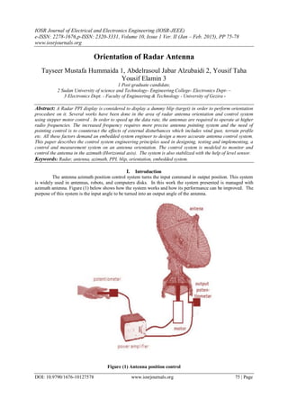
1. IOSR Journal of Electrical and Electronics Engineering (IOSR-JEEE)
e-ISSN: 2278-1676,p-ISSN: 2320-3331, Volume 10, Issue 1 Ver. II (Jan – Feb. 2015), PP 75-78
www.iosrjournals.org
DOI: 10.9790/1676-10127578 www.iosrjournals.org 75 | Page
Orientation of Radar Antenna
Tayseer Mustafa Hummaida 1, Abdelrasoul Jabar Alzubaidi 2, Yousif Taha
Yousif Elamin 3
1 Post graduate candidate,
2 Sudan University of science and Technology- Engineering College- Electronics Dept- –
3 Electronics Dept. - Faculty of Engineering & Technology - University of Gezira -
Abstract: A Radar PPI display is considered to display a dummy blip (target) in order to perform orientation
procedure on it. Several works have been done in the area of radar antenna orientation and control system
using stepper motor control . In order to speed up the data rate, the antennas are required to operate at higher
radio frequencies. The increased frequency requires more precise antenna pointing system and the need of
pointing control is to counteract the effects of external disturbances which includes wind gust, terrain profile
etc. All these factors demand an embedded system engineer to design a more accurate antenna control system.
This paper describes the control system engineering principles used in designing, testing and implementing, a
control and measurement system on an antenna orientation. The control system is modeled to monitor and
control the antenna in the azimuth (Horizontal axis). The system is also stabilized with the help of level sensor.
Keywords: Radar, antenna, azimuth, PPI, blip, orientation, embedded system.
I. Introduction
The antenna azimuth position control system turns the input command in output position. This system
is widely used in antennas, robots, and computers disks. In this work the system presented is managed with
azimuth antenna. Figure (1) below shows how the system works and how its performance can be improved. The
purpose of this system is the input angle to be turned into an output angle of the antenna.
Figure (1) Antenna position control
2. Orientation of Radar Antenna
DOI: 10.9790/1676-10127578 www.iosrjournals.org 76 | Page
The antenna control system representation is shown in figure (2) below.
Figure (2) antenna control system
For improving the control system , an approach of micro-stepping control for the step motors based on
field programmable gate array (FPGA) is presented after the micro-stepping driving theory of the step motor
with a constant torque was discussed deeply. And then the relative control system is schematically designed,
mainly includes the internal logic design of the FPGA, the communication interface design of the
microcomputer, the design of the power driving circuit, and the design of the interface circuit between the
electrical sources. At last, it is verified by some experimental investigations that the control theory and approach
presented are corrective, and the control system designed is very good to get a high precision of position control
and high control repeatability. Therefore, the technology questions from the producing reality are resolved and
the product quality is promoted.
An open loop stepper motor driver using a FPGA is also feasible. The model of the current controller is
described and gains of the controller are selected at optimal values. In this design, the FPGA is used to build a
high performance open loop driver without using a DSP; furthermore it is compatible with ASICs and mass
production methods. The experimental results verify the performance of the driver. In addition, stepper motor
controller is used to drive the stepper motor. A Very High Speed Integrated Circuit Hardware Description
Language (VHDL) is implemented on SPARATAN Field Programmable Gate Array (FPGA). The Proposed
motor controller is a set of Darlington amplifiers thus giving very high precision. Due to high torque of stepper
motor, it is capable of handling the big industrial automation system. In this system, a potentiometer technique
will be designed to give the control parameter to the FPGA, which in its turn controls the stepper motor.
II. Methodology
This paper describes a stepper motor control algorithm designed using VHDL and implemented in
FPGA. The system is capable of controlling the stepper motor in terms of a very small step angle. In addition
to this, we can make it to rotate at different speeds, displacement clockwise and anticlockwise directions. Here
a potentiometer is used for inputting the control parameter to faithfully control the antenna azimuth angle by
rotating the stepper motor clockwise and anticlockwise.
One of the major advantages of the design is its precision. It is user-friendly reduces programming
complexity and errors can be easily identified and rectified . The main block diagram is based guiding the signal
from Plane Position Indicator of the Radar (PPI) to the FPGA. Figure (3) below shows the block diagram of the
system design.
Figure (3) the block diagram of the system
3. Orientation of Radar Antenna
DOI: 10.9790/1676-10127578 www.iosrjournals.org 77 | Page
Hardware component
The hardware components for the electronic circuit design are:
Breadboard:
Breadboard (protoboard) is a construction base for a one-of-a-kind electronic circuit, a prototype.
Because the solder less breadboard does not require soldering, it is reusable, and thus can be used for temporary
prototypes and experimenting with circuit design more easily. A variety of electronic systems may be
prototyped by using breadboards.
Potentiometer:
It is used as a means of pointing to the blip on the PPI of the Radar.
ADC8080:
It is used to transform the analog signal from the PPI of the Radar into digital format to be fed to the FPGA for
processing.
HD74LS373 Latching IC:
The HD74LS373 is eight bit is register I/O mapped used as a buffer, which stores signals for future
use. Different types of latches are available HD74LS373 octal D-type transparent latch will be used in this
system. This type of latch is suitable for driving high capacitive and impedance loads.
ULN 2893A Darlington IC:
The ULN2803A is a high-voltage, high-current Darlington transistor array. The device consists of
eight NPN Darlington pairs that feature high-voltage outputs with common-cathode clamp diodes for switching
inductive loads. The collector-current rating of each Darlington pair is 500 mA. .The Darlington pairs may be
connected in parallel for higher current capability.
Lab link cable:
The lab link cables are used as a connection means in the circuit right from the PPI of the Radar up to
the stepper motor.
Stepper motor:
A stepper motor is used for the procedure of orientation of the antenna of the Radar .The number of
steps of the stepper motor is (200 steps / revolution). Equation (1) gives the value of the step angle of the stepper
motor.
One revolution 3600
Step angle = -------------------- = -------------- = 1.8 Degree --------------- (1)
200 200
III. Algorithm
The algorithm is based on supplying the FPGA through the ADC with the azimuth angle appeared on
the PPI of the Radar in the digital format .The FPGA in its turn processes the data and issues a correction
command to the stepper motor in order to align the antenna to the geographical north (00
) . The orientation
procedure of the Radar antenna is as follows;
.. The transmitter issues a signal.
.. The PPI of the Radar displays the transmitter signal as a dummy target on the PPI.
.. A potentiometer points to the blip (target) to convey the azimuth angle.
.. The ADC transforms the DC voltage into digital format.
.. The FPGA processes the digital data.
.. The FPGA issues correction command to the stepper motor through the interface.
.. The stepper motor aligns the antenna to the geographical north (00
).
VHDL programming language is used for programming the FPGA by the computer the algorithm is:
Start
Initialization:
… Program port (A1) of FPGA as input.
… Program port (A2) of FPGA as output.
--- Put transmitter mode to (OFF).
--- Adjust the plane position indicator (PPI) of the Radar to the geographical north (00
).
4. Orientation of Radar Antenna
DOI: 10.9790/1676-10127578 www.iosrjournals.org 78 | Page
--- Clear output to stepper motor.
Processing:
--- Put transmitter mode to (ON).
---- Call orientation subroutine.
End
Orientation subroutine:
Blip detection:
--- Observe the blip on the PPI of the Radar.
… Move the slide of the potentiometer to coincide with the blip on the PPI.
… Check the incoming azimuth value of the blip.
--- If the azimuth value equals zero, then go to terminate the subroutine.
--- If the azimuth value does not equal zero, then go to antenna position correction.
… Go to blip detection.
Antenna position correction:
… If the azimuth value is positive, then rotate the stepper motor one-step anticlockwise.
… If the azimuth value is negative, then rotate the stepper motor one-step clockwise.
--- Go to blip detection.
Terminate:
Return.
IV. Results
A transmitter tuned to the Radar receiver frequency is used to generate a blip (dummy target) on the
PPI display of the Radar. when applying the algorithm in paragraph (III) above, we observe the location of the
blip on the PPI .Based on the blip azimuth angle, the program in the FPGA performs the alignment of the
antenna with the blip appearance on the PPI of the Radar .The alignment processing continues till we get the
antenna exactly heading to the geographical north (0 Degrees). Each step movement of the stepper motor makes
an antenna azimuth angle correction of (1.8 Degrees) .A mechanical gearing mechanism is implemented to
enhance the stepper motor angle resolution up to of (0.18 Degrees). Table (1) below shows the results obtained
from the generation of four different dummy blips (targets) on the PPI display of the Radar and performing
antenna orientation procedure on them
Table (1) the results obtained from generating a blip (target) on the PPI display of the Radar
Blip azimuth angle on PPI (Degrees) No. of steps of stepper motor Alignment result
+ 180
East 100 anticlockwise Geographical north ( 00
)
-90
West 50 clockwise Geographical north ( 00
)
+ 270
East 150 anticlockwise Geographical north ( 00
)
-13.50
West 75 clockwise Geographical north ( 00
)
Note: The alignment (orientation) can be done by pointing towards (East, South, and West) As well.
V. Conclusion
The functionality of the design starts with activating a transmitter tuned to the Radar frequency. A
dummy blip (target) appears on the PPI display of the Radar. Any antenna azimuth angle deviation from the
geographical north will be subjected to correction procedure. Based on the blip appearance on the PPI, the
FPGA program performs the correction by commanding the stepper motor to rotate clockwise or anticlockwise.
The processing outcome is to put both the antenna and the PPI display on (00
). The alignment procedure
(orientation) makes us avoiding azimuth data capture errors by the Radar.
References
[1]. Mr.N.Sai Pavan, Mr.Ramavenkateswaran.N: MODELLING OF TH STABILIZATIONAND TRACKING CONTROL SYSTEM
FOR ANTENNA, International Journal Of Advanced Research In Computer And Communication Engineering, June 2014.
[2]. Boban Temelkovskia And Jugoslav Achkoskia “Modeling And Simulation Of Antenna Azimuth Position Control System
“International Journal Of Multidisciplinary And Current Research,2014.
[3]. Xiaodong Zhang, Junjun He, And Chunlei Sheng, “Anapproach Of Micro-Stepping Control For The Step Motors Based On FPGA,”
IEEE International Conference On Industrial Technology, Pp. 125 - 130, Dec. 2005.
[4]. Ngoc Quy Le1 And Jae Wook Jeon2” An Open-Loop Stepper Motor Driver Based On FPGA” International Conference On
Control, Automation And Systems 2007Oct. 17-20, 2007 In COEX, Seoul, Korea
[5]. Arvind Kumar1, Mrs. M. Valarmathi2” High Precision Stepper Motor Controller Implementation On FPGA With GUI On
Labview”International Journal Of Advanced Research In Electrical, Electronics And Instrumentation Engineering Vol. 2, Issue 4,
April 2013