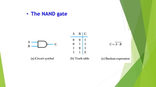
DIGITAL ELECTRONICS
Keywords:
Logic Gates, AND, OR, NOR, NAND
By :-KARAN JADHAV
Logic
Gates
3
Logic Gates
• The building blocks used to create digital circuits
are logic gates
• There are three elementary logic gates and a
range of other simple gates
• Each gate has its own logic symbol which allows
complex functions to be represented by a logic
diagram
• The function of each gate can be represented by a
truth table or using Boolean notation
4
• The AND gate
• The AND gate has the following symbol and truth table.
• Two or more input bits produce one output bit.
• Both inputs must be true (1) for the output to be true.
• Otherwise the output is false (0).
5
• The OR gate
• The OR gate has the following symbol and truth
table.
• Two or more input bits produce one output bit.
• Either inputs must be true (1) for the output to
be true.
6
• The NOT gate (or inverter)
• The simplest possible gate is called an "inverter" or a NOT
gate.
• One bit as input produces its opposite as output.
• The symbol for a NOT gate is shown below.
• The truth table for the NOT gate shows input and output.
7What happens when you add a NOT
to an AND gate?
“Not AND” =
NAND
A B X
0 0 1
0 1 1
1 0 1
1 1 0
8
• The NAND gate
9What happens when you add a NOT
to an OR gate?
“Not OR” = NOR
A B X
0 0 1
0 1 0
1 0 0
1 1 0
10
• The NOR gate
11
• The Exclusive NOR gate
• The Symbol and Truth Table is shown below.
• Output will be high for same inputs
Karan

Karan

  • 1.
    DIGITAL ELECTRONICS Keywords: Logic Gates,AND, OR, NOR, NAND By :-KARAN JADHAV
  • 2.
  • 3.
    3 Logic Gates • Thebuilding blocks used to create digital circuits are logic gates • There are three elementary logic gates and a range of other simple gates • Each gate has its own logic symbol which allows complex functions to be represented by a logic diagram • The function of each gate can be represented by a truth table or using Boolean notation
  • 4.
    4 • The ANDgate • The AND gate has the following symbol and truth table. • Two or more input bits produce one output bit. • Both inputs must be true (1) for the output to be true. • Otherwise the output is false (0).
  • 5.
    5 • The ORgate • The OR gate has the following symbol and truth table. • Two or more input bits produce one output bit. • Either inputs must be true (1) for the output to be true.
  • 6.
    6 • The NOTgate (or inverter) • The simplest possible gate is called an "inverter" or a NOT gate. • One bit as input produces its opposite as output. • The symbol for a NOT gate is shown below. • The truth table for the NOT gate shows input and output.
  • 7.
    7What happens whenyou add a NOT to an AND gate? “Not AND” = NAND A B X 0 0 1 0 1 1 1 0 1 1 1 0
  • 8.
  • 9.
    9What happens whenyou add a NOT to an OR gate? “Not OR” = NOR A B X 0 0 1 0 1 0 1 0 0 1 1 0
  • 10.
  • 11.
    11 • The ExclusiveNOR gate • The Symbol and Truth Table is shown below. • Output will be high for same inputs