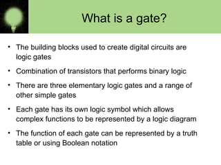
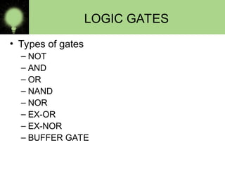
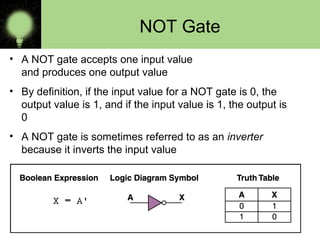
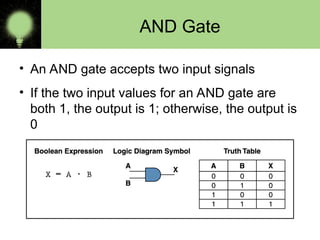
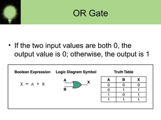
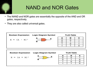
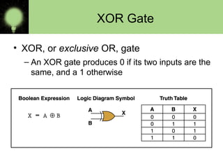
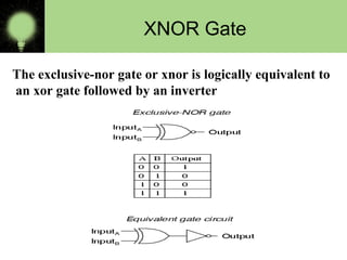
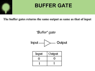
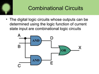
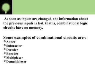
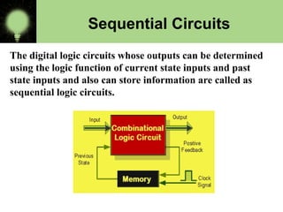
CONTENTS
• Logic Gates
• Truth table
• Types of circuits -:
 Combinational Circuits
 Sequential Circuits
What is a gate?
• The building blocks used to create digital circuits are
logic gates
• Combination of transistors that performs binary logic
• There are three elementary logic gates and a range of
other simple gates
• Each gate has its own logic symbol which allows
complex functions to be represented by a logic diagram
• The function of each gate can be represented by a truth
table or using Boolean notation
LOGIC GATES
• Types of gates
– NOT
– AND
– OR
– NAND
– NOR
– EX-OR
– EX-NOR
– BUFFER GATE
NOT Gate
• A NOT gate accepts one input value
and produces one output value
• By definition, if the input value for a NOT gate is 0, the
output value is 1, and if the input value is 1, the output is
0
• A NOT gate is sometimes referred to as an inverter
because it inverts the input value
AND Gate
• An AND gate accepts two input signals
• If the two input values for an AND gate are
both 1, the output is 1; otherwise, the output is
0
OR Gate
• If the two input values are both 0, the
output value is 0; otherwise, the output is 1
NAND and NOR Gates
• The NAND and NOR gates are essentially the opposite of the AND and OR
gates, respectively.
• They are also called universal gates.
XOR Gate
• XOR, or exclusive OR, gate
– An XOR gate produces 0 if its two inputs are the
same, and a 1 otherwise
XNOR Gate
The exclusive-nor gate or xnor is logically equivalent to
an xor gate followed by an inverter
BUFFER GATE
The buffer gates returns the same output as same as that of input
Combinational Circuits
• The digital logic circuits whose outputs can be
determined using the logic function of current
state input are combinational logic circuits
AND
AND
OR
As soon as inputs are changed, the information about
the previous inputs is lost, that is, combinational logic
circuits have no memory.
Some examples of combinational circuits are-:
Adder
Subtractor
Decoder
Encoder
Multiplexer
Demultiplexer
The digital logic circuits whose outputs can be determined
using the logic function of current state inputs and past
state inputs and also can store information are called as
sequential logic circuits.
Sequential Circuits
It is a combination of memory elements and
combinational gates.
Types of sequential circuits
Flip flops
Registers
Counters
logicgates- basic logic gates and or nand not.ppt

logicgates- basic logic gates and or nand not.ppt

  • 2.
    CONTENTS • Logic Gates •Truth table • Types of circuits -:  Combinational Circuits  Sequential Circuits
  • 3.
    What is agate? • The building blocks used to create digital circuits are logic gates • Combination of transistors that performs binary logic • There are three elementary logic gates and a range of other simple gates • Each gate has its own logic symbol which allows complex functions to be represented by a logic diagram • The function of each gate can be represented by a truth table or using Boolean notation
  • 4.
    LOGIC GATES • Typesof gates – NOT – AND – OR – NAND – NOR – EX-OR – EX-NOR – BUFFER GATE
  • 5.
    NOT Gate • ANOT gate accepts one input value and produces one output value • By definition, if the input value for a NOT gate is 0, the output value is 1, and if the input value is 1, the output is 0 • A NOT gate is sometimes referred to as an inverter because it inverts the input value
  • 6.
    AND Gate • AnAND gate accepts two input signals • If the two input values for an AND gate are both 1, the output is 1; otherwise, the output is 0
  • 7.
    OR Gate • Ifthe two input values are both 0, the output value is 0; otherwise, the output is 1
  • 8.
    NAND and NORGates • The NAND and NOR gates are essentially the opposite of the AND and OR gates, respectively. • They are also called universal gates.
  • 9.
    XOR Gate • XOR,or exclusive OR, gate – An XOR gate produces 0 if its two inputs are the same, and a 1 otherwise
  • 10.
    XNOR Gate The exclusive-norgate or xnor is logically equivalent to an xor gate followed by an inverter
  • 11.
    BUFFER GATE The buffergates returns the same output as same as that of input
  • 12.
    Combinational Circuits • Thedigital logic circuits whose outputs can be determined using the logic function of current state input are combinational logic circuits AND AND OR
  • 13.
    As soon asinputs are changed, the information about the previous inputs is lost, that is, combinational logic circuits have no memory. Some examples of combinational circuits are-: Adder Subtractor Decoder Encoder Multiplexer Demultiplexer
  • 14.
    The digital logiccircuits whose outputs can be determined using the logic function of current state inputs and past state inputs and also can store information are called as sequential logic circuits. Sequential Circuits
  • 15.
    It is acombination of memory elements and combinational gates. Types of sequential circuits Flip flops Registers Counters