Downloaded 486 times


![39
REFERENCES
1. Khurmi,R.S.,&J.K. Gupta (2014).Theory of Machines, S. Chand Publication[page
no.114]
2. Khurmi, R. S., & Gupta, J. K. (2012). Machine Design, S. Chand Publication [page
no.730]
3. Khurmi, R. S., & Gupta, J. K. (2012). Machine Design, S. Chand Publication [page
no.998]
4. Kurvinen, E., Sopanen, J., & Mikkola, A. (2015). Ball bearing model performance on
various sized rotors withand without centrifugal and gyroscopic forces. Mechanism and
Machine Theory, 90, 240-260
5.Naresh,G.Venkatesh,N.S.Vishal,SureshKannan,Thangaprakash,A.Sivasubramanian,
Dr.G.Arunkumar Design and Fabrication of Pedal Operated Hacksaw, 2014 3(11), 197-
198
6. NelsonRE Bandsawing or hacksawing? 1965 109(24), Pages 90-93
7. Raj, K. J. S. D. (2012). Modeling, Controland Prototypingof Alternative Energy
Storage Systems for HybridVehicles (Doctoral dissertation, The Ohio State University).
8. Remmerswaal J Lp Mathysen MJC Economics of the cutting-offof metals
Microtecnic, 196115(4), 140-150
9. Suzuki, A., Miyamoto, K., & Takahashi, S. (1998). U.S. Patent No. 5,791,224.
Washington, DC: U.S. Patent and Trademark Office.
10. Thompson, P. J., & Sarwar, M. (1974, September). Power hacksawing. In Proc. 15th
IMTDR Conf.
11. Usher, A. P. (2013). A History of Mechanical Inventions: Revised Edition. Courier
Corporation.](https://image.slidesharecdn.com/finalreport-160605092355/85/Solar-Powered-Hacksaw-39-320.jpg)

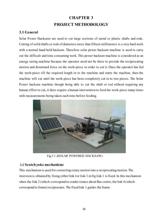
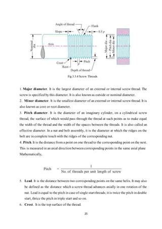
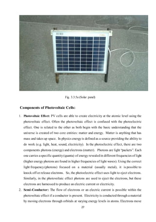
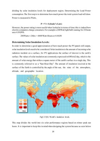
The document is a project report on the design and construction of a solar-powered hacksaw machine aimed at enhancing efficiency in cutting metals. It discusses the methodology, components, and operation of the machine, highlighting its environmental benefits and reduction in manual labor. The report also includes acknowledgments, literature reviews, and key objectives regarding sustainable manufacturing practices.