IRJET- Development of Artificial ARM using Pneumatic Artificial Muscle
•
0 likes•23 views

https://www.irjet.net/archives/V6/i5/IRJET-V6I529.pdf

Recommended
Recommended
More Related Content
What's hot
What's hot (20)
Similar to IRJET- Development of Artificial ARM using Pneumatic Artificial Muscle
Similar to IRJET- Development of Artificial ARM using Pneumatic Artificial Muscle (20)
More from IRJET Journal
More from IRJET Journal (20)
Recently uploaded
Recently uploaded (20)
IRJET- Development of Artificial ARM using Pneumatic Artificial Muscle
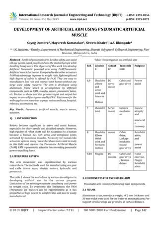
- 1. International Research Journal of Engineering and Technology (IRJET) e-ISSN: 2395-0056 Volume: 06 Issue: 05 | May 2019 www.irjet.net p-ISSN: 2395-0072 © 2019, IRJET | Impact Factor value: 7.211 | ISO 9001:2008 Certified Journal | Page 142 DEVELOPMENT OF ARTIFICIAL ARM USING PNEUMATIC ARTIFICIAL MUSCLE Suyog Dumbre1, Mayuresh Kamatakar2, Shweta Khaire3, A.S. Bhongade4 1,2,3UG Students, 4 Faculty, Department of Mechanical Engineering, Bharati Vidyapeeth College of Engineering, Navi Mumbai, Maharashtra, India ----------------------------------------------------------------------***--------------------------------------------------------------------- Abstract - Artificial pneumatic arm, besides safety, can assist old age people, weak people and alsothedisabledpeople while handling heavy work. The objective of this work is to develop Artificial Pneumatic powered arm using PAM(Pneumatic Artificial muscle) actuator. Compared to the other actuators PAM has advantage in power to weight ratio, lightweight and high degree of safety is offered by PAM. They are easy to manufacture, low cost and interact with human without any large scale safety required. The arm is developed using aluminium frame which is accomplished by different components such as PAM, muscles sensor, pneumatic tubes, etc. Factors as shape and size, pressure input and output has impact on overall force generated by PAM. It is known for the wide application in various aspects such as military, hospital, robotics, automation, etc. Key Words: Pneumatic artificial muscle, muscle sensor, actuator. 1) 1. INTRODUCTION Robots become significant to serve and assist human, especially for older people and disabled people. However, high rigidity of robot joints will be hazardous to a human because a human has soft arms and compliant joints activated by numerous muscles. Necessity for human-like actuators system, many researchershavemotivatedtostudy in this field and created the Pneumatic Artificial Muscle (PAM). PAM is pneumatic actuator forconvertingpneumatic power to pulling force. 2. LITERATURE REVIEW The arm movement was experimented by various researchers. The methods used for manufacturing are gear and cable driven arms, electric motors, hydraulic and pneumatic. The table 1 shows the work done by various investigator in developing artificial arm for the various purpose. Limitations of the existing was more complexity and power to weight ratio. To overcome this limitations the PAM (Pneumatic air muscle) can be experimented as it has properties of high power to weight ratio, and can be easily manufactured Table 1 Investigation on artificial arm Ref. Locatio n Actuat or Transmis sion Purpose 6,9 Shoulder ,elbow and wrist joint and forearm Motion DC servo motor Cable and gear drive Power assist 7 Shoulder Joint Servo motor Geneva mechanis m muscle atrophy and accelerat e recovery 8 Shoulder Elbow Wrist joint and Forearm motion motor Cable drive, Linkage mechanis m and gear drive Rehabilit ation, and power assist 9,10 Fingers DC motors Cable and gear drive , Tendon drives Hand exercise, Finger Rehabilit ation 3. COMPONENTS FOR PNEUMATIC ARM Pneumatic arm consist of following main components. 3.1 FRAME Aluminium strips, to reduce weight, of 2 mm thickness and 30 mm width were used for the frame of pneumaticarm.For support circular rings are provided at certain distance.
- 2. International Research Journal of Engineering and Technology (IRJET) e-ISSN: 2395-0056 Volume: 06 Issue: 05 | May 2019 www.irjet.net p-ISSN: 2395-0072 © 2019, IRJET | Impact Factor value: 7.211 | ISO 9001:2008 Certified Journal | Page 143 Fig 3.1.1 design of frame 3.2 PNEUMATIC AIR MUSCLE PAMs were first developed (under the name of McKiben Artificial Muscles) in the 1950s for use of artificial limbs. They are contractile and extensional devices operated by pressurized air filling a pneumatic bladder. And they can handled pressure upto 50 psi . PAM are used as a actuator. It consist of latex rubber tube surrounded by a tubular braidedfibermeshsleeveknownas flexo tube as shown in fig.1. When the bladder is inflated the mesh expands radially and contracts axially shortening the overall length of muscle and subsequentlyproducingpulling force. Fig 1 Pneumatic air muscle 3.3 THE FITTING PUSH (6MM) Union push-to-connect fittings are available as shown in fig. 2 for use with 3/8. 5/32, 5/16 and ½ inch tube. Tubing connection and tightnessaremadepossiblebystainlesssteel griping collect and o-ring inside fitting. Once inserted to the bottom of the fitting the stainless steel collet grips the tube prevents it from being disconnected until the release button is pushed. Fig 2 Composite union tee 3.4 SOLENOID VALVE 3/2 VALVE A 3/2 way solenoid valve has three ports and tow switching states as shown in fig. 3. By activating solenoid, the valve switches state and different connection between the valve port is established. Fig 3 3/2 solenoid valve 3.5 MUSCLE SENSOR Muscle sensor are used to send signals to the arduino. EMG muscle sensor as shown in fig 4 records the movements of our muscle. Fig 4 EMG muscle sensor 3.6 ARDUINO UNO Arduino uno is used for programming, it is an open source microcontroller board bases on microchip. The board is equipped with set of digital and analog i/o pins that may be interface by circuits. 3.7 AIR COMPRESSOR In both home and commercial application, one of the main roles of an air compressor is to providepowerforpneumatic tools. 4 DEVELOPMENT OF PNEUMATIC ARM The PAM actuated pneumatic arm is fabricatedwiththehelp of aluminium frame, pneumatic air muscle, muscle sensor, arduino UNO, solenoid valves, and air compressor as shown in fig 5. The signals from the hand is collected via muscle sensor and send to the arduino. Analog signals from muscle sensor are converted into digital signals and then processed by arduino and accordingly valves are controlled and
- 3. International Research Journal of Engineering and Technology (IRJET) e-ISSN: 2395-0056 Volume: 06 Issue: 05 | May 2019 www.irjet.net p-ISSN: 2395-0072 © 2019, IRJET | Impact Factor value: 7.211 | ISO 9001:2008 Certified Journal | Page 144 pressurized air is passedthroughPAMandmovementofarm is accomplished. Fig .5 Assembly of pneumatic arm 5. EXPERIMENTATION The working of the arm is demonstrated eith following. 5.1 AIR COMPRESSOR Manufacturing company: Capacity of compressor 5.2 PNEUMATIC AIR MUSCLE Dimension of latex tube: Diameter is 9.5mm and length is 280 mm Dimension of flexo tube : Diameter is 9.5mm and length is 320 mm Hose clamps 5.3 SOLENOID VALVE Body: Aluminium Anodise. Pressure: 0.15 to 0.8 Mpa Volt: 12 V 6. RESULTS The arm developed has working Pressure of 6 Bar The change in length Of Pam and deflection due to load is observed 6 Cm each. The maximum load bearing capacity of the arm is 30kg. 7. CONCLUSION The design and fabrication of pneumatic arm for lifting load is completed with economic and effective consideration.Itis mainly actuated by PAM (Pneumatic air muscle) and the movement of PAM is controlled by electro pneumaticvalves. The signals are sent through muscle sensor attached with hand to arduino and program actuates the valves. The PAMs has a wide choice for application in automation , robotics and material handling device. It gives quick response and flexible compared to hydraulic and electrical type of exoskeleton arm. This is achieved while maintaining simplicity, ease of use, implementation and maintenance. The model is expected to lift object of 30 kg weight. The entire system proved successful in building an air muscle actuated arm to accomplish the task of lifting heavy loads. 8. REFERENCES 1. R. A. R. C. Gopura and K. Kiguchi, “Development of a 6DOF Upper-Limb Exoskeleton Robot,” Int. Conf. on Inform. Automat. For Sustainability, Colombo, Sri Lanka, 2008,pp. 13-18 2. H. Kawasaki, S. Ito, Y. Ishigure, and Y. Nishimoto, T. Aoki, T. Mouri, H. SakaedaandM.Abe, “Development of a Hand Motion Assist Robot for Rehabilitation Therapy byPatient Self-Motion Control,” in Proc. IEEE Int. Conf. on Rehabil. Robotics, NoordwijkThe Netherlands 2007, pp.234-240. 3. D.Sasaki,T.Noritsugu,andM.Takaiwa,“Developme ntofActiveSupportSplintDrivenby PneumaticSoftActuator(ASSIST),”J.RoboticsandM echatronics,vol.16,pp.497-502, 2004. 4. A.GuptaandJosephL.McKibben,“Designofahaptica rmexoskeletonfortrainingand rehabilitation,”IEEE/ASMETrans.Mechatronics,v ol.11,pp.280–289,2006. 5. A. Gupta and M. K. O’Malley, “Design of a haptic arm exoskeleton for training and rehabilitation,” IEEE/ASME Trans. Mechatronics, vol. 11,pp. 280–289,2006. 6. https://en.wikipedia.org/wiki/Pneumatic_artific ial_muscles 7. E. Papadopoulos and G. Patsianis, “Design of an Exoskeleton Mechanism for the shoulder Jointin Proc. Twelfth World Congr. In Mechanism and Machine Sci, Besancon, France, 2007, pp. 1-6 8. M. Mulas, M. Folgheraiter, and G. Gini, “An EMG- Controlled Exoskeleton forHandRehabilitation”, in Proc. Int. Conf. on Rehabil Robotics, Chicago, Illinois, USA, 2005pp. 371-374 9. I. Sarakoglou, N. G. Tsagarakis,andD.G.Caldwell, “Occupational and Physical Therapy Using A Hand ExoskeletonBased Exerciser,”inProc.IEEE Int. Conf. on Intell. Robots and Syst., vol. 3, Sendai, Japan, 2004, pp 2973- 2978. 10. A. Wege and G. Hommel, “Development and Control of a Hand Exoskeleton for Rehabilitation of Hand Injuries,” in Proc. IEEE/RSJ Int. Conf. on Intell. Robots and Syst., Alberto, Canada, 2005, pp. 3046-3051