SlideShare a Scribd company logo
1 of 6
Download to read offline
International Research Journal of Engineering and Technology (IRJET) e-ISSN: 2395-0056
Volume: 10 Issue: 03 | Mar 2023 www.irjet.net p-ISSN: 2395-0072
© 2023, IRJET | Impact Factor value: 8.226 | ISO 9001:2008 Certified Journal | Page 93
Experimental Study and Investigation of Helical Pipe Heat Exchanger
with Varying Pitch
M. Ramesh Babu1, D. Ratnababu2, P. Syam3
1M.Tech student, Thermal Engineering, Department of Mechanical Engineering, Newton’s Institute of Science &
Technology, Macherla, A.P.
2Assistant Professor, Department of Mechanical Engineering, Newton’s Institute of Science & Technology,
Macherla, A.P.
3 Assistant Professor & HOD, Department of Mechanical Engineering, Newton’s Institute of Science & Technology,
Macherla, A.P.
---------------------------------------------------------------------***---------------------------------------------------------------------
Abstract -
Heat exchangers are the most researched and
constantly evolved devices in the research industry. This
project is an attempt on experimental investigationofhelical
coil heat exchangers and its best effectiveness for different
pitch values but the rest of the dimensions kept constant. In
the process of enhancing the heat transfer capacity of heat
exchangers the helical pipe heat exchangers have come inas
a passive method of heat enhancement. The reason for this
would be that the flow in the helical coils always produces a
secondary flow component to the radial velocity. This
additional component is the result of centrifugal forcedueto
flow in the curvature.
Present research work is to understand more
behavioral effects on the helical pipe heat exchanger on the
pitch of the helix is selected. Normal design procedure is
followed to design the heat exchanger but the option to vary
the pitch of the helix is provided.
The helical coil is enclosed in a vessel to simulate the shell
side of heat exchanger. The cold fluid enters the shell
through the bottom connection and flows up. It leaves the
shell through the outlet at the top. The coil is welded to a
bottom flange plate in such a way that coilassemblyremains
fixed at the bottom of the assembly.Byvaryingtheflowrates
of the hot and cold water experiment was conducted for all
the pith selected. The effectiveness was calculated for each
case. Results and plots were recorded
Key Words: helical pipe heat exchanger, helix pitch
1. INTRODUCTION
Heatexchangersarethemostresearchedandconstantly
evolved devices in the research industry. Basically a Heat
exchanger is a device that accommodates the transferofheat
from one fluid to other. It basically consists of an
arrangement to allow two fluids; usually liquids to flow in
two different passages may be concentric tubes or anyother
pattern.
As weknow heat exchanger is a deviceinwhichtheheat
energy in the form of enthalpy is transferredfromonefluidto
another fluid through the solid medium with or without
external work involved. Major applicationofheatexchangers
involve the heat transfer between the two fluids either
evaporation or condensation or just controlling the
temperature of the fluid of concern. In many medical or
chemical industry related applications it would be with an
intention of sterilizing, pasteurizing, distilling, fractionating,
crystallizing or also control process the fluid.
1.1 Shell And Tube Heat Exchanger
A shell and tube heat exchanger is one of the classes of heat
exchanger types. It is the most commonly used type of heat
exchanger in chemical processesandotheroilrefineries.This
type of heat exchanger is best suited for high-pressure and
high-temperature applications. This type of heat exchanger
basically consists of a shell (a large enclosure to withstand
pressure) with a single or bundle of tubes enclosed.Amongst
the two fluids, one flows through the shell and the other
through the tubes. The surface of the tubes helps the heat
transfer from the outer flowing fluid to theinsidefluidorvice
versa depending on the temperature gradient between the
two fluids. If a set of tubes is enclosed in the shell then that
set is called bundle of tubes.A tube bundle may be composed
by different types of tubes with or without finslongitudinally
attached to the tubes. The figure below shows a typical shell
and tube heat exchangers.
Fig 1.1: Typical Shell And Tube Heat Exchanger
International Research Journal of Engineering and Technology (IRJET) e-ISSN: 2395-0056
Volume: 10 Issue: 03 | Mar 2023 www.irjet.net p-ISSN: 2395-0072
© 2023, IRJET | Impact Factor value: 8.226 | ISO 9001:2008 Certified Journal | Page 94
1.2 Helical Pipe Heat Exchanger
In this type of heat exchanger the tube is formed into the
helical pipe and placed inside the shell. This provides a
secondary flow to the fluid flowing in this pipe. A schematic
of the helical pipe heat exchanger is shown in the following
figure.
Fig 1.2: Helical Pipe Heat Exchanger
In the process of enhancing the heat transfer capacity of
heat exchangers the helical pipe heat exchangers have come
in as a passive method of heat enhancement. The reason for
this would be that the flow in the helical coils always
produces a secondary flow component to the radial velocity.
This additional component is the result of centrifugal force
due to flow in the curvature.
As lot of literatureis available to proveabouttheflowpattern
that is generated in the helical and other curved channels. It
is also seen thata symmetrical paired vortices usuallyaffects
the main flow stream of the fluid. Also the details of these
flow characteristics are discussed in the literature survey.
2. EXPERIMENTAL SETUP
The pipe used to construct the helical section has 10mm
inside diameter and 12.7mm outer diameter. The tube
material is copper. The PitchCircleDiameter(PCD)ofthecoil
is 80mm and tube pitch is 20mm. The remaining parts of the
setup are made of mild steel. The helical coil is enclosed in a
vessel to simulate the shell side of heat exchanger. The cold
fluid enters the shell through the bottom connection and
flows up. It leaves the shell through the outlet at the top. The
coil is welded to a bottom flange plate in such a way that coil
assembly remains fixed at the bottom of the assembly. A
manually controlled mechanism is provided to push andpull
the coil according to the need.
The helical coil test section is connected to a loop, which
provides the necessary flow through the tube and shell side
of the test section and the required instrumentation. A tank
with electric heater is provided to heat the water to be
circulated through the helical coil with a total power of
2000W. The manufactured experimentalsetupisasshownin
the following figure.
Fig 2.1: experimental setup
In the process of enhancing the heat transfer capacity of a
heat exchangers the helical pipe heat exchangers have come
in as a passive method of heat enhancement. The reason for
this would be that the flow in the helical coils always
produces a secondary flow component to the radial velocity.
3. METHODOLOGY
3.1 Design Procedure
Fig 3.1: sectional view of the helical coil heat exchanger
The design was calculated as per the following equations
1) The coil tube length L for N number of turns
𝐿 = 𝑁√ (2𝜋𝑟) 2 + 𝑝2 (1)
2) The volume utilized by the coil, Vc:
Vc = ( π/4) d20L (2)
3) Annulus volume available, Va :
Va = ( π/4) (C2 – B2) 𝑝N (3)
4) The available volume for the fluid to flow in the annulus,
Vf :
Vf = 𝑉𝑎 – 𝑉c (4)
International Research Journal of Engineering and Technology (IRJET) e-ISSN: 2395-0056
Volume: 10 Issue: 03 | Mar 2023 www.irjet.net p-ISSN: 2395-0072
© 2023, IRJET | Impact Factor value: 8.226 | ISO 9001:2008 Certified Journal | Page 95
5) Equivalent diameter of the coiled tube for shell-side,
De:
𝐷𝑒 = 4𝑉𝑓/ 𝜋𝑑𝑜𝐿 (5)
3.2 Design Calculations
Assumed Number of coils N = 10
Radius of the helical is r = 80 mm
Pitch of the helical is p = 20 mm
do= 80+6.35 = 86.35 mm
di = 80-6.35 = 73.65 mm
B = 73.35 – 6.35 = 67.3 mm
C = 86.35 + (1.5 ∗12.7) = 105.4 mm
Therefore:
𝐿 = 10√ (2𝜋 80) 2 + 202= 2016 mm = 2.016 m
Vc = ( π/4) 86.352 ∗ 2016 = 1470 m3
Va = ( π/4) (105.42 – 67.32) 20 ∗ 10 = 1.033 m3
𝑉𝑓 = 14.70 − 1.033 = 13.667 m3
𝐷𝑒 = (4 ∗ 13.667 ∗ 106) / ( π ∗ 86.35 ∗ 2016) = 99.96 mm
4. RESULTS AND DISCUSSION
The experiment was conducted for different
parameters. The results are tabulated as follows.
Case 1: Full Length
4.1 Gap between Coils = 20 Mm, Parallel Flow & Full
Length
4.1.1 For Constant Cold water flow as 1 LPM
Table 4.1 Temperatures recorded for 20 mm gap between
coils 1 LPM Cold water constant flow
Table 4.2: Calculated Effectiveness for 20 mm gap between
coils 1 LPM Cold water constant flow
Fig 4.1: Plot for effectiveness 20 mm gap between coils,
Parallel flow, Cold water Flow rate 1 LPM
Sample Calculation
Heat Flow capacity of cold water:
Cc = mcCpc where for water Cpc = 4.187 kJ/ kg K
mc = 1 LPM = (1000 * 10-6 * 1000) / 60 = 0.0167 kg/s
∴ Cc = 0.0167 * 4.187 = 69.91121 kJ / K
Heat Flow capacity of Hot water:
Ch = mhCph where for water Cph = 4.187 kJ/ kg K
.mh = 1 LPM = (600 * 106 * 1000) / 60 = 0.01 kg/s
∴ Ch = 0.0167 * 4.187 = 41.87 kJ / K
From the above we can see that:
Cmin = 41.87 kJ / K and Cmax = 69.91121 kJ / K
Maximum Heat transfer theoretically:
Qmax = Cmin ( th1 – tc1) = 41.87 ( 69 – 38 ) = 1297.753 kJ
/ s
Heat Transfer in Cold water:
Qc = mc ( tc2 – tc1 ) = 0.0167 ( 43 – 38 ) = 349.5978 kJ / s
Heat Transfer in hot water:
Qh = mh ( th1 – th2 ) = 0.01 ( 69 – 46 ) = 1608.15 kJ / s
Hot Water
Temperature 0C
Cold Water
Temperature 0C
Flow Rate Of
Hot Water
(kg/s)
Flow Rate Of
Cold Water
(kg/s)
Inlet Outlet Inlet Outlet
0.01 0.0167 69 46 38 43
0.0133 0.0167 69 57 39 47
0.0167 0.0167 69 56 38 47
Ch Cc Cmin Qmax Qh Qc Q Ε
41.86 69.91 41.86 1297.75 1608.15 349.59 978.87 0.75
55.67 69.91 55.67 1670.33 839.03 559.35 699.19 0.41
69.91 69.91 69.91 2167.24 908.95 629.27 769.11 0.35
International Research Journal of Engineering and Technology (IRJET) e-ISSN: 2395-0056
Volume: 10 Issue: 03 | Mar 2023 www.irjet.net p-ISSN: 2395-0072
© 2023, IRJET | Impact Factor value: 8.226 | ISO 9001:2008 Certified Journal | Page 96
Average Heat transfer:
Q = ( Qh+Qc) / 2 = ( 1608.15 + 359.5978 ) / 2 = 978.8738
Effectiveness:
ε= ( Q / Qavg ) = 978.8738 / 1297.753
ε = 0.754284
4.1.2 For Constant Hot water flow as 1 LPM
Fig 4.2: Plot for effectiveness 20 mm Gap between coils,
Parallel flow, Hot water Flow rate 1 LPM
4.2 Gap between Coils = 20 Mm, Counter Flow & Full
Length
Table 4.3: Temperatures recorded for 20 mm gap between
coils 1 LPM Cold water constant flow
4.2.1 For Constant Cold water flow as 1 LPM
Table 4.4: Calculated Effectiveness for 20 mm gap between
coils 1 LPM Cold water constant flow
Fig 4.3 Plot for effectiveness 20 mm Gap between coils,
Counter flow, Cold water Flow rate 1 LPM
4.2.2 For Constant Hot water flow as 1 LPM
Fig 4.4: Plot for effectiveness 20 mm Gap between coils,
Counter flow, Hot water Flow rate 1 LPM
Similarly the work was continued for 10 mm pitchand0 mm
pitch for full length pipe with same flow conditions in cold
and hot flow and the results are shown below.
Fig 4.5: Plot for effectiveness Vs Mass flow rate
consolidated for parallel flow (cold water flow rate 1LPM)
Hot Water
Temperature
0C
Cold Water
Temperature
0C
Flow Rate Of
Hot Water
(kg/s)
Flow Rate Of
Cold Water
(kg/s)
Inlet Outlet Inlet Outlet
0.01 0.0167 70 53 36 49
0.0133 0.0167 69 56 38 50
0.0167 0.0167 69 57 37 50
Ch Cc Cmin Qmax Qh Qc Q Ε
41.86 69.91 41.86 1423.34 1188.63 908.95 1048.79 0.73
55.67 69.91 55.67 1781.68 978.87 839.03 908.95 0.51
69.91 69.91 69.91 2237.15 839.03 908.95 873.99 0.39
International Research Journal of Engineering and Technology (IRJET) e-ISSN: 2395-0056
Volume: 10 Issue: 03 | Mar 2023 www.irjet.net p-ISSN: 2395-0072
© 2023, IRJET | Impact Factor value: 8.226 | ISO 9001:2008 Certified Journal | Page 97
Fig 4.6: Plot for effectiveness Vs Mass flow rate
consolidated for counter flow. (cold water flow rate 1LPM)
Fig 4.7: Plot for effectiveness Vs Mass flow rate
consolidated for Parallel flow (Hot water flow rate 1LPM)
Fig 4.8: Plot for effectiveness Vs Mass flow rate
consolidated for counter flow (Hot water flow rate 1LPM)
For half length:
Fig 4.9: Plot for effectiveness Vs Mass flow rate
consolidated for parallel flow, for half length (cold water
flow rate 1LPM)
Fig 4.10: Plot for effectiveness Vs Mass flow rate
consolidated for counter flow, for half length (cold water
flow rate 1LPM)
Fig 4.11: Plot for effectiveness Vs Mass flow rate
consolidated for Parallel flow, for half length (Hot water
flow rate 1LPM)
International Research Journal of Engineering and Technology (IRJET) e-ISSN: 2395-0056
Volume: 10 Issue: 03 | Mar 2023 www.irjet.net p-ISSN: 2395-0072
© 2023, IRJET | Impact Factor value: 8.226 | ISO 9001:2008 Certified Journal | Page 98
Fig 4.12: Plot for effectiveness Vs Mass flow rate
consolidated for counter flow for half length (Hot water
flow rate 1LPM)
4.3 POWER LOSSES
Fig 4.13: losses when cold water flow rate maintained at
0.0167 kg/s.
Fig 4.13: losses when hot water flow rate maintained at
0.0167 kg/s
5. CONCLUSIONS
The heat exchanger was designed first according to the
normal design procedure. The heat exchanger was
manufactured as the dimensions obtained from the design.
The samewas repeated for the different flowratesofthecold
water, keeping thehotwaterflowrateconstant.Effectiveness
was calculated for all the flow rates. The work was done for
pitch of 20 mm,10 mm,0 mm in full length and half length
conditions.
We observe that the effectiveness ingeneralreduceswiththe
increase of the mass flow rate irrespective of the pitch.
From the research it can be easily conclude from the results
that when the gap between the coils was 10 mm and 0 mm
the effectiveness was consistentforbothparallelandcounter
flow arrangements, in both half length and full length
readings.
The consolidated graphs plotted also reveal for the half
length readings that the length chosen according to the
design i.e. 2 m is accurate and the length of the copper pipe
cannot be reduced further.
It is been observed that when power losses were calculated
and plotted accordingly, the maximum power loss has
occurred when the flow rate of cold fluid was 0.6 kg/s at 10
mm gap between the coils for counter flow. And the value
was 72.76%. It is also observed that the minimum power
losses are occurred at when the hot fluid flow rate was
maintained at 0.6 kg/s when there was no gap between the
coils for parallel flow arrangement. And the value was
25.58%.
REFERENCES
[1] “ Numerical and experimental studies of a double-
pipe helical heat exchanger” by Timothy j. Rennie
department of bioresource engineering, mcgill university,
montreal, submitted august 2004, a thesis submitted to
mcgill university in partial fulfillment of the requirements of
the degree of doctor of philosophy.
[2] “Helically Coiled Heat Exchangers - Basic design
Applications” by J. S. Jayakumar Professor, Dept. of
Mechanical Engineering, Amrita Vishwa Vidyapeetham,
Amrita School of Engineering, Amritapuri, Kollam, India.
[3] “Fabrication and Analysis of Tube-In-Tube Helical
Coil Heat Exchanger” by Mrunal P.Kshirsagar, Trupti J.
Kansara, Swapnil M. Aher, International Journal of
Engineering Research andGeneral ScienceVolume2,Issue3,
April-May 2014 ISSN 2091-2730.
[4] “ Thermal Analysis of a Helical Coil Heat
Exchanger”by Amol Andhare, V M Kriplani, J P Modak,
International Journal of Innovative Research in Advanced
Engineering (IJIRAE) ISSN: 2349-2163
[5] “Thermal Analysis Validation for Different Design
Tubes in a Heat Exchanger” byRoshan.V.MarodeandAshok.
J.Keche, International Journal of Engineering Research and
General Science Volume 3, Issue 1, January-February, 2015,
ISSN 2091-2730.

More Related Content

Similar to Experimental Study and Investigation of Helical Pipe Heat Exchanger with Varying Pitch

IRJET-Experimental Study on Helical Tube Heat Exchanger by Varying Cross Sect...
IRJET-Experimental Study on Helical Tube Heat Exchanger by Varying Cross Sect...IRJET-Experimental Study on Helical Tube Heat Exchanger by Varying Cross Sect...
IRJET-Experimental Study on Helical Tube Heat Exchanger by Varying Cross Sect...IRJET Journal
 
Esign and thermal evaluation of shell and helical coil heat exchanger
Esign and thermal evaluation of shell and helical coil heat exchangerEsign and thermal evaluation of shell and helical coil heat exchanger
Esign and thermal evaluation of shell and helical coil heat exchangereSAT Journals
 
IRJET- Heat Exchanger Analysis and Method to Improve its Effectiveness
IRJET-  	  Heat Exchanger Analysis and Method to Improve its EffectivenessIRJET-  	  Heat Exchanger Analysis and Method to Improve its Effectiveness
IRJET- Heat Exchanger Analysis and Method to Improve its EffectivenessIRJET Journal
 
IRJET- CFD Analysis of Double Pipe Heat Exchanger with Different Inner Se...
IRJET-  	  CFD Analysis of Double Pipe Heat Exchanger with Different Inner Se...IRJET-  	  CFD Analysis of Double Pipe Heat Exchanger with Different Inner Se...
IRJET- CFD Analysis of Double Pipe Heat Exchanger with Different Inner Se...IRJET Journal
 
IRJET- Design and Study of Triangular Plate and Fin Heat Exchanger
	IRJET- Design and Study of Triangular Plate and Fin Heat Exchanger	IRJET- Design and Study of Triangular Plate and Fin Heat Exchanger
IRJET- Design and Study of Triangular Plate and Fin Heat ExchangerIRJET Journal
 
IRJET- Experimental Analysis on Performance of Closed Loop Pulsating Heat Pip...
IRJET- Experimental Analysis on Performance of Closed Loop Pulsating Heat Pip...IRJET- Experimental Analysis on Performance of Closed Loop Pulsating Heat Pip...
IRJET- Experimental Analysis on Performance of Closed Loop Pulsating Heat Pip...IRJET Journal
 
SPEECH EMOTION RECOGNITION SYSTEM USING RNN
SPEECH EMOTION RECOGNITION SYSTEM USING RNNSPEECH EMOTION RECOGNITION SYSTEM USING RNN
SPEECH EMOTION RECOGNITION SYSTEM USING RNNIRJET Journal
 
Heat Transfer Enhancement of Shell and Tube Heat Exchanger Using Conical Tapes.
Heat Transfer Enhancement of Shell and Tube Heat Exchanger Using Conical Tapes.Heat Transfer Enhancement of Shell and Tube Heat Exchanger Using Conical Tapes.
Heat Transfer Enhancement of Shell and Tube Heat Exchanger Using Conical Tapes.IJERA Editor
 
IRJET- Modelling and CFD Simulation of Prototype of AC Plant Chiller On-Board...
IRJET- Modelling and CFD Simulation of Prototype of AC Plant Chiller On-Board...IRJET- Modelling and CFD Simulation of Prototype of AC Plant Chiller On-Board...
IRJET- Modelling and CFD Simulation of Prototype of AC Plant Chiller On-Board...IRJET Journal
 
PERFORMANCE ENHANCEMENT OF HEAT EXCHANGERS USING VORTEX FLAPS
PERFORMANCE ENHANCEMENT OF HEAT EXCHANGERS USING VORTEX FLAPSPERFORMANCE ENHANCEMENT OF HEAT EXCHANGERS USING VORTEX FLAPS
PERFORMANCE ENHANCEMENT OF HEAT EXCHANGERS USING VORTEX FLAPSIRJET Journal
 
Experimentation of Heat Pipe Used In Nano-Fluids
Experimentation of Heat Pipe Used In Nano-FluidsExperimentation of Heat Pipe Used In Nano-Fluids
Experimentation of Heat Pipe Used In Nano-Fluidspaperpublications3
 
IRJET- A Review on Basics of Heat Exchanger
IRJET-  	  A Review on Basics of Heat ExchangerIRJET-  	  A Review on Basics of Heat Exchanger
IRJET- A Review on Basics of Heat ExchangerIRJET Journal
 
IRJET - Performance Analysis of a Double Pipe Heat Exchanger with and wit...
IRJET -  	  Performance Analysis of a Double Pipe Heat Exchanger with and wit...IRJET -  	  Performance Analysis of a Double Pipe Heat Exchanger with and wit...
IRJET - Performance Analysis of a Double Pipe Heat Exchanger with and wit...IRJET Journal
 
IRJET- Experimental Investigation of Enhancement of Convective Heat Trans...
IRJET-  	  Experimental Investigation of Enhancement of Convective Heat Trans...IRJET-  	  Experimental Investigation of Enhancement of Convective Heat Trans...
IRJET- Experimental Investigation of Enhancement of Convective Heat Trans...IRJET Journal
 
IRJET - Review of Entropy Generation Minimization in Heat Exchanger
IRJET - Review of Entropy Generation Minimization in Heat ExchangerIRJET - Review of Entropy Generation Minimization in Heat Exchanger
IRJET - Review of Entropy Generation Minimization in Heat ExchangerIRJET Journal
 
Evaluation of Convective Heat Transfer Coefficient of Air Flowing Through an ...
Evaluation of Convective Heat Transfer Coefficient of Air Flowing Through an ...Evaluation of Convective Heat Transfer Coefficient of Air Flowing Through an ...
Evaluation of Convective Heat Transfer Coefficient of Air Flowing Through an ...Bishal Bhandari
 
IRJET- Heat Transfer Enhancement of Parallel Flow and Counter Flow Heat E...
IRJET-  	  Heat Transfer Enhancement of Parallel Flow and Counter Flow Heat E...IRJET-  	  Heat Transfer Enhancement of Parallel Flow and Counter Flow Heat E...
IRJET- Heat Transfer Enhancement of Parallel Flow and Counter Flow Heat E...IRJET Journal
 
Analysis of Heat Transfer in Spiral Plate Heat Exchanger Using Experimental a...
Analysis of Heat Transfer in Spiral Plate Heat Exchanger Using Experimental a...Analysis of Heat Transfer in Spiral Plate Heat Exchanger Using Experimental a...
Analysis of Heat Transfer in Spiral Plate Heat Exchanger Using Experimental a...ijsrd.com
 
IRJET-Numerical Investigation of Heat Performance Enhancement for a Double-Pi...
IRJET-Numerical Investigation of Heat Performance Enhancement for a Double-Pi...IRJET-Numerical Investigation of Heat Performance Enhancement for a Double-Pi...
IRJET-Numerical Investigation of Heat Performance Enhancement for a Double-Pi...IRJET Journal
 

Similar to Experimental Study and Investigation of Helical Pipe Heat Exchanger with Varying Pitch (20)

IRJET-Experimental Study on Helical Tube Heat Exchanger by Varying Cross Sect...
IRJET-Experimental Study on Helical Tube Heat Exchanger by Varying Cross Sect...IRJET-Experimental Study on Helical Tube Heat Exchanger by Varying Cross Sect...
IRJET-Experimental Study on Helical Tube Heat Exchanger by Varying Cross Sect...
 
Esign and thermal evaluation of shell and helical coil heat exchanger
Esign and thermal evaluation of shell and helical coil heat exchangerEsign and thermal evaluation of shell and helical coil heat exchanger
Esign and thermal evaluation of shell and helical coil heat exchanger
 
IRJET- Heat Exchanger Analysis and Method to Improve its Effectiveness
IRJET-  	  Heat Exchanger Analysis and Method to Improve its EffectivenessIRJET-  	  Heat Exchanger Analysis and Method to Improve its Effectiveness
IRJET- Heat Exchanger Analysis and Method to Improve its Effectiveness
 
IRJET- CFD Analysis of Double Pipe Heat Exchanger with Different Inner Se...
IRJET-  	  CFD Analysis of Double Pipe Heat Exchanger with Different Inner Se...IRJET-  	  CFD Analysis of Double Pipe Heat Exchanger with Different Inner Se...
IRJET- CFD Analysis of Double Pipe Heat Exchanger with Different Inner Se...
 
IRJET- Design and Study of Triangular Plate and Fin Heat Exchanger
	IRJET- Design and Study of Triangular Plate and Fin Heat Exchanger	IRJET- Design and Study of Triangular Plate and Fin Heat Exchanger
IRJET- Design and Study of Triangular Plate and Fin Heat Exchanger
 
IRJET- Experimental Analysis on Performance of Closed Loop Pulsating Heat Pip...
IRJET- Experimental Analysis on Performance of Closed Loop Pulsating Heat Pip...IRJET- Experimental Analysis on Performance of Closed Loop Pulsating Heat Pip...
IRJET- Experimental Analysis on Performance of Closed Loop Pulsating Heat Pip...
 
REPORT-MSD
REPORT-MSDREPORT-MSD
REPORT-MSD
 
SPEECH EMOTION RECOGNITION SYSTEM USING RNN
SPEECH EMOTION RECOGNITION SYSTEM USING RNNSPEECH EMOTION RECOGNITION SYSTEM USING RNN
SPEECH EMOTION RECOGNITION SYSTEM USING RNN
 
Heat Transfer Enhancement of Shell and Tube Heat Exchanger Using Conical Tapes.
Heat Transfer Enhancement of Shell and Tube Heat Exchanger Using Conical Tapes.Heat Transfer Enhancement of Shell and Tube Heat Exchanger Using Conical Tapes.
Heat Transfer Enhancement of Shell and Tube Heat Exchanger Using Conical Tapes.
 
IRJET- Modelling and CFD Simulation of Prototype of AC Plant Chiller On-Board...
IRJET- Modelling and CFD Simulation of Prototype of AC Plant Chiller On-Board...IRJET- Modelling and CFD Simulation of Prototype of AC Plant Chiller On-Board...
IRJET- Modelling and CFD Simulation of Prototype of AC Plant Chiller On-Board...
 
PERFORMANCE ENHANCEMENT OF HEAT EXCHANGERS USING VORTEX FLAPS
PERFORMANCE ENHANCEMENT OF HEAT EXCHANGERS USING VORTEX FLAPSPERFORMANCE ENHANCEMENT OF HEAT EXCHANGERS USING VORTEX FLAPS
PERFORMANCE ENHANCEMENT OF HEAT EXCHANGERS USING VORTEX FLAPS
 
Experimentation of Heat Pipe Used In Nano-Fluids
Experimentation of Heat Pipe Used In Nano-FluidsExperimentation of Heat Pipe Used In Nano-Fluids
Experimentation of Heat Pipe Used In Nano-Fluids
 
IRJET- A Review on Basics of Heat Exchanger
IRJET-  	  A Review on Basics of Heat ExchangerIRJET-  	  A Review on Basics of Heat Exchanger
IRJET- A Review on Basics of Heat Exchanger
 
IRJET - Performance Analysis of a Double Pipe Heat Exchanger with and wit...
IRJET -  	  Performance Analysis of a Double Pipe Heat Exchanger with and wit...IRJET -  	  Performance Analysis of a Double Pipe Heat Exchanger with and wit...
IRJET - Performance Analysis of a Double Pipe Heat Exchanger with and wit...
 
IRJET- Experimental Investigation of Enhancement of Convective Heat Trans...
IRJET-  	  Experimental Investigation of Enhancement of Convective Heat Trans...IRJET-  	  Experimental Investigation of Enhancement of Convective Heat Trans...
IRJET- Experimental Investigation of Enhancement of Convective Heat Trans...
 
IRJET - Review of Entropy Generation Minimization in Heat Exchanger
IRJET - Review of Entropy Generation Minimization in Heat ExchangerIRJET - Review of Entropy Generation Minimization in Heat Exchanger
IRJET - Review of Entropy Generation Minimization in Heat Exchanger
 
Evaluation of Convective Heat Transfer Coefficient of Air Flowing Through an ...
Evaluation of Convective Heat Transfer Coefficient of Air Flowing Through an ...Evaluation of Convective Heat Transfer Coefficient of Air Flowing Through an ...
Evaluation of Convective Heat Transfer Coefficient of Air Flowing Through an ...
 
IRJET- Heat Transfer Enhancement of Parallel Flow and Counter Flow Heat E...
IRJET-  	  Heat Transfer Enhancement of Parallel Flow and Counter Flow Heat E...IRJET-  	  Heat Transfer Enhancement of Parallel Flow and Counter Flow Heat E...
IRJET- Heat Transfer Enhancement of Parallel Flow and Counter Flow Heat E...
 
Analysis of Heat Transfer in Spiral Plate Heat Exchanger Using Experimental a...
Analysis of Heat Transfer in Spiral Plate Heat Exchanger Using Experimental a...Analysis of Heat Transfer in Spiral Plate Heat Exchanger Using Experimental a...
Analysis of Heat Transfer in Spiral Plate Heat Exchanger Using Experimental a...
 
IRJET-Numerical Investigation of Heat Performance Enhancement for a Double-Pi...
IRJET-Numerical Investigation of Heat Performance Enhancement for a Double-Pi...IRJET-Numerical Investigation of Heat Performance Enhancement for a Double-Pi...
IRJET-Numerical Investigation of Heat Performance Enhancement for a Double-Pi...
 

More from IRJET Journal

TUNNELING IN HIMALAYAS WITH NATM METHOD: A SPECIAL REFERENCES TO SUNGAL TUNNE...
TUNNELING IN HIMALAYAS WITH NATM METHOD: A SPECIAL REFERENCES TO SUNGAL TUNNE...TUNNELING IN HIMALAYAS WITH NATM METHOD: A SPECIAL REFERENCES TO SUNGAL TUNNE...
TUNNELING IN HIMALAYAS WITH NATM METHOD: A SPECIAL REFERENCES TO SUNGAL TUNNE...IRJET Journal
 
STUDY THE EFFECT OF RESPONSE REDUCTION FACTOR ON RC FRAMED STRUCTURE
STUDY THE EFFECT OF RESPONSE REDUCTION FACTOR ON RC FRAMED STRUCTURESTUDY THE EFFECT OF RESPONSE REDUCTION FACTOR ON RC FRAMED STRUCTURE
STUDY THE EFFECT OF RESPONSE REDUCTION FACTOR ON RC FRAMED STRUCTUREIRJET Journal
 
A COMPARATIVE ANALYSIS OF RCC ELEMENT OF SLAB WITH STARK STEEL (HYSD STEEL) A...
A COMPARATIVE ANALYSIS OF RCC ELEMENT OF SLAB WITH STARK STEEL (HYSD STEEL) A...A COMPARATIVE ANALYSIS OF RCC ELEMENT OF SLAB WITH STARK STEEL (HYSD STEEL) A...
A COMPARATIVE ANALYSIS OF RCC ELEMENT OF SLAB WITH STARK STEEL (HYSD STEEL) A...IRJET Journal
 
Effect of Camber and Angles of Attack on Airfoil Characteristics
Effect of Camber and Angles of Attack on Airfoil CharacteristicsEffect of Camber and Angles of Attack on Airfoil Characteristics
Effect of Camber and Angles of Attack on Airfoil CharacteristicsIRJET Journal
 
A Review on the Progress and Challenges of Aluminum-Based Metal Matrix Compos...
A Review on the Progress and Challenges of Aluminum-Based Metal Matrix Compos...A Review on the Progress and Challenges of Aluminum-Based Metal Matrix Compos...
A Review on the Progress and Challenges of Aluminum-Based Metal Matrix Compos...IRJET Journal
 
Dynamic Urban Transit Optimization: A Graph Neural Network Approach for Real-...
Dynamic Urban Transit Optimization: A Graph Neural Network Approach for Real-...Dynamic Urban Transit Optimization: A Graph Neural Network Approach for Real-...
Dynamic Urban Transit Optimization: A Graph Neural Network Approach for Real-...IRJET Journal
 
Structural Analysis and Design of Multi-Storey Symmetric and Asymmetric Shape...
Structural Analysis and Design of Multi-Storey Symmetric and Asymmetric Shape...Structural Analysis and Design of Multi-Storey Symmetric and Asymmetric Shape...
Structural Analysis and Design of Multi-Storey Symmetric and Asymmetric Shape...IRJET Journal
 
A Review of “Seismic Response of RC Structures Having Plan and Vertical Irreg...
A Review of “Seismic Response of RC Structures Having Plan and Vertical Irreg...A Review of “Seismic Response of RC Structures Having Plan and Vertical Irreg...
A Review of “Seismic Response of RC Structures Having Plan and Vertical Irreg...IRJET Journal
 
A REVIEW ON MACHINE LEARNING IN ADAS
A REVIEW ON MACHINE LEARNING IN ADASA REVIEW ON MACHINE LEARNING IN ADAS
A REVIEW ON MACHINE LEARNING IN ADASIRJET Journal
 
Long Term Trend Analysis of Precipitation and Temperature for Asosa district,...
Long Term Trend Analysis of Precipitation and Temperature for Asosa district,...Long Term Trend Analysis of Precipitation and Temperature for Asosa district,...
Long Term Trend Analysis of Precipitation and Temperature for Asosa district,...IRJET Journal
 
P.E.B. Framed Structure Design and Analysis Using STAAD Pro
P.E.B. Framed Structure Design and Analysis Using STAAD ProP.E.B. Framed Structure Design and Analysis Using STAAD Pro
P.E.B. Framed Structure Design and Analysis Using STAAD ProIRJET Journal
 
A Review on Innovative Fiber Integration for Enhanced Reinforcement of Concre...
A Review on Innovative Fiber Integration for Enhanced Reinforcement of Concre...A Review on Innovative Fiber Integration for Enhanced Reinforcement of Concre...
A Review on Innovative Fiber Integration for Enhanced Reinforcement of Concre...IRJET Journal
 
Survey Paper on Cloud-Based Secured Healthcare System
Survey Paper on Cloud-Based Secured Healthcare SystemSurvey Paper on Cloud-Based Secured Healthcare System
Survey Paper on Cloud-Based Secured Healthcare SystemIRJET Journal
 
Review on studies and research on widening of existing concrete bridges
Review on studies and research on widening of existing concrete bridgesReview on studies and research on widening of existing concrete bridges
Review on studies and research on widening of existing concrete bridgesIRJET Journal
 
React based fullstack edtech web application
React based fullstack edtech web applicationReact based fullstack edtech web application
React based fullstack edtech web applicationIRJET Journal
 
A Comprehensive Review of Integrating IoT and Blockchain Technologies in the ...
A Comprehensive Review of Integrating IoT and Blockchain Technologies in the ...A Comprehensive Review of Integrating IoT and Blockchain Technologies in the ...
A Comprehensive Review of Integrating IoT and Blockchain Technologies in the ...IRJET Journal
 
A REVIEW ON THE PERFORMANCE OF COCONUT FIBRE REINFORCED CONCRETE.
A REVIEW ON THE PERFORMANCE OF COCONUT FIBRE REINFORCED CONCRETE.A REVIEW ON THE PERFORMANCE OF COCONUT FIBRE REINFORCED CONCRETE.
A REVIEW ON THE PERFORMANCE OF COCONUT FIBRE REINFORCED CONCRETE.IRJET Journal
 
Optimizing Business Management Process Workflows: The Dynamic Influence of Mi...
Optimizing Business Management Process Workflows: The Dynamic Influence of Mi...Optimizing Business Management Process Workflows: The Dynamic Influence of Mi...
Optimizing Business Management Process Workflows: The Dynamic Influence of Mi...IRJET Journal
 
Multistoried and Multi Bay Steel Building Frame by using Seismic Design
Multistoried and Multi Bay Steel Building Frame by using Seismic DesignMultistoried and Multi Bay Steel Building Frame by using Seismic Design
Multistoried and Multi Bay Steel Building Frame by using Seismic DesignIRJET Journal
 
Cost Optimization of Construction Using Plastic Waste as a Sustainable Constr...
Cost Optimization of Construction Using Plastic Waste as a Sustainable Constr...Cost Optimization of Construction Using Plastic Waste as a Sustainable Constr...
Cost Optimization of Construction Using Plastic Waste as a Sustainable Constr...IRJET Journal
 

More from IRJET Journal (20)

TUNNELING IN HIMALAYAS WITH NATM METHOD: A SPECIAL REFERENCES TO SUNGAL TUNNE...
TUNNELING IN HIMALAYAS WITH NATM METHOD: A SPECIAL REFERENCES TO SUNGAL TUNNE...TUNNELING IN HIMALAYAS WITH NATM METHOD: A SPECIAL REFERENCES TO SUNGAL TUNNE...
TUNNELING IN HIMALAYAS WITH NATM METHOD: A SPECIAL REFERENCES TO SUNGAL TUNNE...
 
STUDY THE EFFECT OF RESPONSE REDUCTION FACTOR ON RC FRAMED STRUCTURE
STUDY THE EFFECT OF RESPONSE REDUCTION FACTOR ON RC FRAMED STRUCTURESTUDY THE EFFECT OF RESPONSE REDUCTION FACTOR ON RC FRAMED STRUCTURE
STUDY THE EFFECT OF RESPONSE REDUCTION FACTOR ON RC FRAMED STRUCTURE
 
A COMPARATIVE ANALYSIS OF RCC ELEMENT OF SLAB WITH STARK STEEL (HYSD STEEL) A...
A COMPARATIVE ANALYSIS OF RCC ELEMENT OF SLAB WITH STARK STEEL (HYSD STEEL) A...A COMPARATIVE ANALYSIS OF RCC ELEMENT OF SLAB WITH STARK STEEL (HYSD STEEL) A...
A COMPARATIVE ANALYSIS OF RCC ELEMENT OF SLAB WITH STARK STEEL (HYSD STEEL) A...
 
Effect of Camber and Angles of Attack on Airfoil Characteristics
Effect of Camber and Angles of Attack on Airfoil CharacteristicsEffect of Camber and Angles of Attack on Airfoil Characteristics
Effect of Camber and Angles of Attack on Airfoil Characteristics
 
A Review on the Progress and Challenges of Aluminum-Based Metal Matrix Compos...
A Review on the Progress and Challenges of Aluminum-Based Metal Matrix Compos...A Review on the Progress and Challenges of Aluminum-Based Metal Matrix Compos...
A Review on the Progress and Challenges of Aluminum-Based Metal Matrix Compos...
 
Dynamic Urban Transit Optimization: A Graph Neural Network Approach for Real-...
Dynamic Urban Transit Optimization: A Graph Neural Network Approach for Real-...Dynamic Urban Transit Optimization: A Graph Neural Network Approach for Real-...
Dynamic Urban Transit Optimization: A Graph Neural Network Approach for Real-...
 
Structural Analysis and Design of Multi-Storey Symmetric and Asymmetric Shape...
Structural Analysis and Design of Multi-Storey Symmetric and Asymmetric Shape...Structural Analysis and Design of Multi-Storey Symmetric and Asymmetric Shape...
Structural Analysis and Design of Multi-Storey Symmetric and Asymmetric Shape...
 
A Review of “Seismic Response of RC Structures Having Plan and Vertical Irreg...
A Review of “Seismic Response of RC Structures Having Plan and Vertical Irreg...A Review of “Seismic Response of RC Structures Having Plan and Vertical Irreg...
A Review of “Seismic Response of RC Structures Having Plan and Vertical Irreg...
 
A REVIEW ON MACHINE LEARNING IN ADAS
A REVIEW ON MACHINE LEARNING IN ADASA REVIEW ON MACHINE LEARNING IN ADAS
A REVIEW ON MACHINE LEARNING IN ADAS
 
Long Term Trend Analysis of Precipitation and Temperature for Asosa district,...
Long Term Trend Analysis of Precipitation and Temperature for Asosa district,...Long Term Trend Analysis of Precipitation and Temperature for Asosa district,...
Long Term Trend Analysis of Precipitation and Temperature for Asosa district,...
 
P.E.B. Framed Structure Design and Analysis Using STAAD Pro
P.E.B. Framed Structure Design and Analysis Using STAAD ProP.E.B. Framed Structure Design and Analysis Using STAAD Pro
P.E.B. Framed Structure Design and Analysis Using STAAD Pro
 
A Review on Innovative Fiber Integration for Enhanced Reinforcement of Concre...
A Review on Innovative Fiber Integration for Enhanced Reinforcement of Concre...A Review on Innovative Fiber Integration for Enhanced Reinforcement of Concre...
A Review on Innovative Fiber Integration for Enhanced Reinforcement of Concre...
 
Survey Paper on Cloud-Based Secured Healthcare System
Survey Paper on Cloud-Based Secured Healthcare SystemSurvey Paper on Cloud-Based Secured Healthcare System
Survey Paper on Cloud-Based Secured Healthcare System
 
Review on studies and research on widening of existing concrete bridges
Review on studies and research on widening of existing concrete bridgesReview on studies and research on widening of existing concrete bridges
Review on studies and research on widening of existing concrete bridges
 
React based fullstack edtech web application
React based fullstack edtech web applicationReact based fullstack edtech web application
React based fullstack edtech web application
 
A Comprehensive Review of Integrating IoT and Blockchain Technologies in the ...
A Comprehensive Review of Integrating IoT and Blockchain Technologies in the ...A Comprehensive Review of Integrating IoT and Blockchain Technologies in the ...
A Comprehensive Review of Integrating IoT and Blockchain Technologies in the ...
 
A REVIEW ON THE PERFORMANCE OF COCONUT FIBRE REINFORCED CONCRETE.
A REVIEW ON THE PERFORMANCE OF COCONUT FIBRE REINFORCED CONCRETE.A REVIEW ON THE PERFORMANCE OF COCONUT FIBRE REINFORCED CONCRETE.
A REVIEW ON THE PERFORMANCE OF COCONUT FIBRE REINFORCED CONCRETE.
 
Optimizing Business Management Process Workflows: The Dynamic Influence of Mi...
Optimizing Business Management Process Workflows: The Dynamic Influence of Mi...Optimizing Business Management Process Workflows: The Dynamic Influence of Mi...
Optimizing Business Management Process Workflows: The Dynamic Influence of Mi...
 
Multistoried and Multi Bay Steel Building Frame by using Seismic Design
Multistoried and Multi Bay Steel Building Frame by using Seismic DesignMultistoried and Multi Bay Steel Building Frame by using Seismic Design
Multistoried and Multi Bay Steel Building Frame by using Seismic Design
 
Cost Optimization of Construction Using Plastic Waste as a Sustainable Constr...
Cost Optimization of Construction Using Plastic Waste as a Sustainable Constr...Cost Optimization of Construction Using Plastic Waste as a Sustainable Constr...
Cost Optimization of Construction Using Plastic Waste as a Sustainable Constr...
 

Recently uploaded

Artificial-Intelligence-in-Electronics (K).pptx
Artificial-Intelligence-in-Electronics (K).pptxArtificial-Intelligence-in-Electronics (K).pptx
Artificial-Intelligence-in-Electronics (K).pptxbritheesh05
 
IVE Industry Focused Event - Defence Sector 2024
IVE Industry Focused Event - Defence Sector 2024IVE Industry Focused Event - Defence Sector 2024
IVE Industry Focused Event - Defence Sector 2024Mark Billinghurst
 
VICTOR MAESTRE RAMIREZ - Planetary Defender on NASA's Double Asteroid Redirec...
VICTOR MAESTRE RAMIREZ - Planetary Defender on NASA's Double Asteroid Redirec...VICTOR MAESTRE RAMIREZ - Planetary Defender on NASA's Double Asteroid Redirec...
VICTOR MAESTRE RAMIREZ - Planetary Defender on NASA's Double Asteroid Redirec...VICTOR MAESTRE RAMIREZ
 
CCS355 Neural Network & Deep Learning Unit II Notes with Question bank .pdf
CCS355 Neural Network & Deep Learning Unit II Notes with Question bank .pdfCCS355 Neural Network & Deep Learning Unit II Notes with Question bank .pdf
CCS355 Neural Network & Deep Learning Unit II Notes with Question bank .pdfAsst.prof M.Gokilavani
 
Decoding Kotlin - Your guide to solving the mysterious in Kotlin.pptx
Decoding Kotlin - Your guide to solving the mysterious in Kotlin.pptxDecoding Kotlin - Your guide to solving the mysterious in Kotlin.pptx
Decoding Kotlin - Your guide to solving the mysterious in Kotlin.pptxJoão Esperancinha
 
Call Girls Narol 7397865700 Independent Call Girls
Call Girls Narol 7397865700 Independent Call GirlsCall Girls Narol 7397865700 Independent Call Girls
Call Girls Narol 7397865700 Independent Call Girlsssuser7cb4ff
 
APPLICATIONS-AC/DC DRIVES-OPERATING CHARACTERISTICS
APPLICATIONS-AC/DC DRIVES-OPERATING CHARACTERISTICSAPPLICATIONS-AC/DC DRIVES-OPERATING CHARACTERISTICS
APPLICATIONS-AC/DC DRIVES-OPERATING CHARACTERISTICSKurinjimalarL3
 
INFLUENCE OF NANOSILICA ON THE PROPERTIES OF CONCRETE
INFLUENCE OF NANOSILICA ON THE PROPERTIES OF CONCRETEINFLUENCE OF NANOSILICA ON THE PROPERTIES OF CONCRETE
INFLUENCE OF NANOSILICA ON THE PROPERTIES OF CONCRETEroselinkalist12
 
Electronically Controlled suspensions system .pdf
Electronically Controlled suspensions system .pdfElectronically Controlled suspensions system .pdf
Electronically Controlled suspensions system .pdfme23b1001
 
Application of Residue Theorem to evaluate real integrations.pptx
Application of Residue Theorem to evaluate real integrations.pptxApplication of Residue Theorem to evaluate real integrations.pptx
Application of Residue Theorem to evaluate real integrations.pptx959SahilShah
 
main PPT.pptx of girls hostel security using rfid
main PPT.pptx of girls hostel security using rfidmain PPT.pptx of girls hostel security using rfid
main PPT.pptx of girls hostel security using rfidNikhilNagaraju
 
What are the advantages and disadvantages of membrane structures.pptx
What are the advantages and disadvantages of membrane structures.pptxWhat are the advantages and disadvantages of membrane structures.pptx
What are the advantages and disadvantages of membrane structures.pptxwendy cai
 
Introduction to Microprocesso programming and interfacing.pptx
Introduction to Microprocesso programming and interfacing.pptxIntroduction to Microprocesso programming and interfacing.pptx
Introduction to Microprocesso programming and interfacing.pptxvipinkmenon1
 
complete construction, environmental and economics information of biomass com...
complete construction, environmental and economics information of biomass com...complete construction, environmental and economics information of biomass com...
complete construction, environmental and economics information of biomass com...asadnawaz62
 
Sachpazis Costas: Geotechnical Engineering: A student's Perspective Introduction
Sachpazis Costas: Geotechnical Engineering: A student's Perspective IntroductionSachpazis Costas: Geotechnical Engineering: A student's Perspective Introduction
Sachpazis Costas: Geotechnical Engineering: A student's Perspective IntroductionDr.Costas Sachpazis
 
Current Transformer Drawing and GTP for MSETCL
Current Transformer Drawing and GTP for MSETCLCurrent Transformer Drawing and GTP for MSETCL
Current Transformer Drawing and GTP for MSETCLDeelipZope
 
Study on Air-Water & Water-Water Heat Exchange in a Finned Tube Exchanger
Study on Air-Water & Water-Water Heat Exchange in a Finned Tube ExchangerStudy on Air-Water & Water-Water Heat Exchange in a Finned Tube Exchanger
Study on Air-Water & Water-Water Heat Exchange in a Finned Tube ExchangerAnamika Sarkar
 
VIP Call Girls Service Hitech City Hyderabad Call +91-8250192130
VIP Call Girls Service Hitech City Hyderabad Call +91-8250192130VIP Call Girls Service Hitech City Hyderabad Call +91-8250192130
VIP Call Girls Service Hitech City Hyderabad Call +91-8250192130Suhani Kapoor
 
Concrete Mix Design - IS 10262-2019 - .pptx
Concrete Mix Design - IS 10262-2019 - .pptxConcrete Mix Design - IS 10262-2019 - .pptx
Concrete Mix Design - IS 10262-2019 - .pptxKartikeyaDwivedi3
 

Recently uploaded (20)

Artificial-Intelligence-in-Electronics (K).pptx
Artificial-Intelligence-in-Electronics (K).pptxArtificial-Intelligence-in-Electronics (K).pptx
Artificial-Intelligence-in-Electronics (K).pptx
 
IVE Industry Focused Event - Defence Sector 2024
IVE Industry Focused Event - Defence Sector 2024IVE Industry Focused Event - Defence Sector 2024
IVE Industry Focused Event - Defence Sector 2024
 
VICTOR MAESTRE RAMIREZ - Planetary Defender on NASA's Double Asteroid Redirec...
VICTOR MAESTRE RAMIREZ - Planetary Defender on NASA's Double Asteroid Redirec...VICTOR MAESTRE RAMIREZ - Planetary Defender on NASA's Double Asteroid Redirec...
VICTOR MAESTRE RAMIREZ - Planetary Defender on NASA's Double Asteroid Redirec...
 
CCS355 Neural Network & Deep Learning Unit II Notes with Question bank .pdf
CCS355 Neural Network & Deep Learning Unit II Notes with Question bank .pdfCCS355 Neural Network & Deep Learning Unit II Notes with Question bank .pdf
CCS355 Neural Network & Deep Learning Unit II Notes with Question bank .pdf
 
Decoding Kotlin - Your guide to solving the mysterious in Kotlin.pptx
Decoding Kotlin - Your guide to solving the mysterious in Kotlin.pptxDecoding Kotlin - Your guide to solving the mysterious in Kotlin.pptx
Decoding Kotlin - Your guide to solving the mysterious in Kotlin.pptx
 
Call Girls Narol 7397865700 Independent Call Girls
Call Girls Narol 7397865700 Independent Call GirlsCall Girls Narol 7397865700 Independent Call Girls
Call Girls Narol 7397865700 Independent Call Girls
 
APPLICATIONS-AC/DC DRIVES-OPERATING CHARACTERISTICS
APPLICATIONS-AC/DC DRIVES-OPERATING CHARACTERISTICSAPPLICATIONS-AC/DC DRIVES-OPERATING CHARACTERISTICS
APPLICATIONS-AC/DC DRIVES-OPERATING CHARACTERISTICS
 
INFLUENCE OF NANOSILICA ON THE PROPERTIES OF CONCRETE
INFLUENCE OF NANOSILICA ON THE PROPERTIES OF CONCRETEINFLUENCE OF NANOSILICA ON THE PROPERTIES OF CONCRETE
INFLUENCE OF NANOSILICA ON THE PROPERTIES OF CONCRETE
 
Electronically Controlled suspensions system .pdf
Electronically Controlled suspensions system .pdfElectronically Controlled suspensions system .pdf
Electronically Controlled suspensions system .pdf
 
Application of Residue Theorem to evaluate real integrations.pptx
Application of Residue Theorem to evaluate real integrations.pptxApplication of Residue Theorem to evaluate real integrations.pptx
Application of Residue Theorem to evaluate real integrations.pptx
 
main PPT.pptx of girls hostel security using rfid
main PPT.pptx of girls hostel security using rfidmain PPT.pptx of girls hostel security using rfid
main PPT.pptx of girls hostel security using rfid
 
What are the advantages and disadvantages of membrane structures.pptx
What are the advantages and disadvantages of membrane structures.pptxWhat are the advantages and disadvantages of membrane structures.pptx
What are the advantages and disadvantages of membrane structures.pptx
 
Introduction to Microprocesso programming and interfacing.pptx
Introduction to Microprocesso programming and interfacing.pptxIntroduction to Microprocesso programming and interfacing.pptx
Introduction to Microprocesso programming and interfacing.pptx
 
complete construction, environmental and economics information of biomass com...
complete construction, environmental and economics information of biomass com...complete construction, environmental and economics information of biomass com...
complete construction, environmental and economics information of biomass com...
 
Sachpazis Costas: Geotechnical Engineering: A student's Perspective Introduction
Sachpazis Costas: Geotechnical Engineering: A student's Perspective IntroductionSachpazis Costas: Geotechnical Engineering: A student's Perspective Introduction
Sachpazis Costas: Geotechnical Engineering: A student's Perspective Introduction
 
young call girls in Rajiv Chowk🔝 9953056974 🔝 Delhi escort Service
young call girls in Rajiv Chowk🔝 9953056974 🔝 Delhi escort Serviceyoung call girls in Rajiv Chowk🔝 9953056974 🔝 Delhi escort Service
young call girls in Rajiv Chowk🔝 9953056974 🔝 Delhi escort Service
 
Current Transformer Drawing and GTP for MSETCL
Current Transformer Drawing and GTP for MSETCLCurrent Transformer Drawing and GTP for MSETCL
Current Transformer Drawing and GTP for MSETCL
 
Study on Air-Water & Water-Water Heat Exchange in a Finned Tube Exchanger
Study on Air-Water & Water-Water Heat Exchange in a Finned Tube ExchangerStudy on Air-Water & Water-Water Heat Exchange in a Finned Tube Exchanger
Study on Air-Water & Water-Water Heat Exchange in a Finned Tube Exchanger
 
VIP Call Girls Service Hitech City Hyderabad Call +91-8250192130
VIP Call Girls Service Hitech City Hyderabad Call +91-8250192130VIP Call Girls Service Hitech City Hyderabad Call +91-8250192130
VIP Call Girls Service Hitech City Hyderabad Call +91-8250192130
 
Concrete Mix Design - IS 10262-2019 - .pptx
Concrete Mix Design - IS 10262-2019 - .pptxConcrete Mix Design - IS 10262-2019 - .pptx
Concrete Mix Design - IS 10262-2019 - .pptx
 

Experimental Study and Investigation of Helical Pipe Heat Exchanger with Varying Pitch

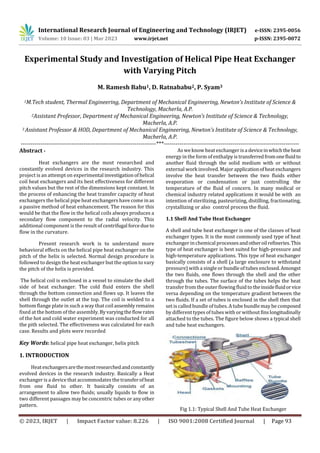
  • 1. International Research Journal of Engineering and Technology (IRJET) e-ISSN: 2395-0056 Volume: 10 Issue: 03 | Mar 2023 www.irjet.net p-ISSN: 2395-0072 © 2023, IRJET | Impact Factor value: 8.226 | ISO 9001:2008 Certified Journal | Page 93 Experimental Study and Investigation of Helical Pipe Heat Exchanger with Varying Pitch M. Ramesh Babu1, D. Ratnababu2, P. Syam3 1M.Tech student, Thermal Engineering, Department of Mechanical Engineering, Newton’s Institute of Science & Technology, Macherla, A.P. 2Assistant Professor, Department of Mechanical Engineering, Newton’s Institute of Science & Technology, Macherla, A.P. 3 Assistant Professor & HOD, Department of Mechanical Engineering, Newton’s Institute of Science & Technology, Macherla, A.P. ---------------------------------------------------------------------***--------------------------------------------------------------------- Abstract - Heat exchangers are the most researched and constantly evolved devices in the research industry. This project is an attempt on experimental investigationofhelical coil heat exchangers and its best effectiveness for different pitch values but the rest of the dimensions kept constant. In the process of enhancing the heat transfer capacity of heat exchangers the helical pipe heat exchangers have come inas a passive method of heat enhancement. The reason for this would be that the flow in the helical coils always produces a secondary flow component to the radial velocity. This additional component is the result of centrifugal forcedueto flow in the curvature. Present research work is to understand more behavioral effects on the helical pipe heat exchanger on the pitch of the helix is selected. Normal design procedure is followed to design the heat exchanger but the option to vary the pitch of the helix is provided. The helical coil is enclosed in a vessel to simulate the shell side of heat exchanger. The cold fluid enters the shell through the bottom connection and flows up. It leaves the shell through the outlet at the top. The coil is welded to a bottom flange plate in such a way that coilassemblyremains fixed at the bottom of the assembly.Byvaryingtheflowrates of the hot and cold water experiment was conducted for all the pith selected. The effectiveness was calculated for each case. Results and plots were recorded Key Words: helical pipe heat exchanger, helix pitch 1. INTRODUCTION Heatexchangersarethemostresearchedandconstantly evolved devices in the research industry. Basically a Heat exchanger is a device that accommodates the transferofheat from one fluid to other. It basically consists of an arrangement to allow two fluids; usually liquids to flow in two different passages may be concentric tubes or anyother pattern. As weknow heat exchanger is a deviceinwhichtheheat energy in the form of enthalpy is transferredfromonefluidto another fluid through the solid medium with or without external work involved. Major applicationofheatexchangers involve the heat transfer between the two fluids either evaporation or condensation or just controlling the temperature of the fluid of concern. In many medical or chemical industry related applications it would be with an intention of sterilizing, pasteurizing, distilling, fractionating, crystallizing or also control process the fluid. 1.1 Shell And Tube Heat Exchanger A shell and tube heat exchanger is one of the classes of heat exchanger types. It is the most commonly used type of heat exchanger in chemical processesandotheroilrefineries.This type of heat exchanger is best suited for high-pressure and high-temperature applications. This type of heat exchanger basically consists of a shell (a large enclosure to withstand pressure) with a single or bundle of tubes enclosed.Amongst the two fluids, one flows through the shell and the other through the tubes. The surface of the tubes helps the heat transfer from the outer flowing fluid to theinsidefluidorvice versa depending on the temperature gradient between the two fluids. If a set of tubes is enclosed in the shell then that set is called bundle of tubes.A tube bundle may be composed by different types of tubes with or without finslongitudinally attached to the tubes. The figure below shows a typical shell and tube heat exchangers. Fig 1.1: Typical Shell And Tube Heat Exchanger
  • 2. International Research Journal of Engineering and Technology (IRJET) e-ISSN: 2395-0056 Volume: 10 Issue: 03 | Mar 2023 www.irjet.net p-ISSN: 2395-0072 © 2023, IRJET | Impact Factor value: 8.226 | ISO 9001:2008 Certified Journal | Page 94 1.2 Helical Pipe Heat Exchanger In this type of heat exchanger the tube is formed into the helical pipe and placed inside the shell. This provides a secondary flow to the fluid flowing in this pipe. A schematic of the helical pipe heat exchanger is shown in the following figure. Fig 1.2: Helical Pipe Heat Exchanger In the process of enhancing the heat transfer capacity of heat exchangers the helical pipe heat exchangers have come in as a passive method of heat enhancement. The reason for this would be that the flow in the helical coils always produces a secondary flow component to the radial velocity. This additional component is the result of centrifugal force due to flow in the curvature. As lot of literatureis available to proveabouttheflowpattern that is generated in the helical and other curved channels. It is also seen thata symmetrical paired vortices usuallyaffects the main flow stream of the fluid. Also the details of these flow characteristics are discussed in the literature survey. 2. EXPERIMENTAL SETUP The pipe used to construct the helical section has 10mm inside diameter and 12.7mm outer diameter. The tube material is copper. The PitchCircleDiameter(PCD)ofthecoil is 80mm and tube pitch is 20mm. The remaining parts of the setup are made of mild steel. The helical coil is enclosed in a vessel to simulate the shell side of heat exchanger. The cold fluid enters the shell through the bottom connection and flows up. It leaves the shell through the outlet at the top. The coil is welded to a bottom flange plate in such a way that coil assembly remains fixed at the bottom of the assembly. A manually controlled mechanism is provided to push andpull the coil according to the need. The helical coil test section is connected to a loop, which provides the necessary flow through the tube and shell side of the test section and the required instrumentation. A tank with electric heater is provided to heat the water to be circulated through the helical coil with a total power of 2000W. The manufactured experimentalsetupisasshownin the following figure. Fig 2.1: experimental setup In the process of enhancing the heat transfer capacity of a heat exchangers the helical pipe heat exchangers have come in as a passive method of heat enhancement. The reason for this would be that the flow in the helical coils always produces a secondary flow component to the radial velocity. 3. METHODOLOGY 3.1 Design Procedure Fig 3.1: sectional view of the helical coil heat exchanger The design was calculated as per the following equations 1) The coil tube length L for N number of turns 𝐿 = 𝑁√ (2𝜋𝑟) 2 + 𝑝2 (1) 2) The volume utilized by the coil, Vc: Vc = ( π/4) d20L (2) 3) Annulus volume available, Va : Va = ( π/4) (C2 – B2) 𝑝N (3) 4) The available volume for the fluid to flow in the annulus, Vf : Vf = 𝑉𝑎 – 𝑉c (4)
  • 3. International Research Journal of Engineering and Technology (IRJET) e-ISSN: 2395-0056 Volume: 10 Issue: 03 | Mar 2023 www.irjet.net p-ISSN: 2395-0072 © 2023, IRJET | Impact Factor value: 8.226 | ISO 9001:2008 Certified Journal | Page 95 5) Equivalent diameter of the coiled tube for shell-side, De: 𝐷𝑒 = 4𝑉𝑓/ 𝜋𝑑𝑜𝐿 (5) 3.2 Design Calculations Assumed Number of coils N = 10 Radius of the helical is r = 80 mm Pitch of the helical is p = 20 mm do= 80+6.35 = 86.35 mm di = 80-6.35 = 73.65 mm B = 73.35 – 6.35 = 67.3 mm C = 86.35 + (1.5 ∗12.7) = 105.4 mm Therefore: 𝐿 = 10√ (2𝜋 80) 2 + 202= 2016 mm = 2.016 m Vc = ( π/4) 86.352 ∗ 2016 = 1470 m3 Va = ( π/4) (105.42 – 67.32) 20 ∗ 10 = 1.033 m3 𝑉𝑓 = 14.70 − 1.033 = 13.667 m3 𝐷𝑒 = (4 ∗ 13.667 ∗ 106) / ( π ∗ 86.35 ∗ 2016) = 99.96 mm 4. RESULTS AND DISCUSSION The experiment was conducted for different parameters. The results are tabulated as follows. Case 1: Full Length 4.1 Gap between Coils = 20 Mm, Parallel Flow & Full Length 4.1.1 For Constant Cold water flow as 1 LPM Table 4.1 Temperatures recorded for 20 mm gap between coils 1 LPM Cold water constant flow Table 4.2: Calculated Effectiveness for 20 mm gap between coils 1 LPM Cold water constant flow Fig 4.1: Plot for effectiveness 20 mm gap between coils, Parallel flow, Cold water Flow rate 1 LPM Sample Calculation Heat Flow capacity of cold water: Cc = mcCpc where for water Cpc = 4.187 kJ/ kg K mc = 1 LPM = (1000 * 10-6 * 1000) / 60 = 0.0167 kg/s ∴ Cc = 0.0167 * 4.187 = 69.91121 kJ / K Heat Flow capacity of Hot water: Ch = mhCph where for water Cph = 4.187 kJ/ kg K .mh = 1 LPM = (600 * 106 * 1000) / 60 = 0.01 kg/s ∴ Ch = 0.0167 * 4.187 = 41.87 kJ / K From the above we can see that: Cmin = 41.87 kJ / K and Cmax = 69.91121 kJ / K Maximum Heat transfer theoretically: Qmax = Cmin ( th1 – tc1) = 41.87 ( 69 – 38 ) = 1297.753 kJ / s Heat Transfer in Cold water: Qc = mc ( tc2 – tc1 ) = 0.0167 ( 43 – 38 ) = 349.5978 kJ / s Heat Transfer in hot water: Qh = mh ( th1 – th2 ) = 0.01 ( 69 – 46 ) = 1608.15 kJ / s Hot Water Temperature 0C Cold Water Temperature 0C Flow Rate Of Hot Water (kg/s) Flow Rate Of Cold Water (kg/s) Inlet Outlet Inlet Outlet 0.01 0.0167 69 46 38 43 0.0133 0.0167 69 57 39 47 0.0167 0.0167 69 56 38 47 Ch Cc Cmin Qmax Qh Qc Q Ε 41.86 69.91 41.86 1297.75 1608.15 349.59 978.87 0.75 55.67 69.91 55.67 1670.33 839.03 559.35 699.19 0.41 69.91 69.91 69.91 2167.24 908.95 629.27 769.11 0.35
  • 4. International Research Journal of Engineering and Technology (IRJET) e-ISSN: 2395-0056 Volume: 10 Issue: 03 | Mar 2023 www.irjet.net p-ISSN: 2395-0072 © 2023, IRJET | Impact Factor value: 8.226 | ISO 9001:2008 Certified Journal | Page 96 Average Heat transfer: Q = ( Qh+Qc) / 2 = ( 1608.15 + 359.5978 ) / 2 = 978.8738 Effectiveness: ε= ( Q / Qavg ) = 978.8738 / 1297.753 ε = 0.754284 4.1.2 For Constant Hot water flow as 1 LPM Fig 4.2: Plot for effectiveness 20 mm Gap between coils, Parallel flow, Hot water Flow rate 1 LPM 4.2 Gap between Coils = 20 Mm, Counter Flow & Full Length Table 4.3: Temperatures recorded for 20 mm gap between coils 1 LPM Cold water constant flow 4.2.1 For Constant Cold water flow as 1 LPM Table 4.4: Calculated Effectiveness for 20 mm gap between coils 1 LPM Cold water constant flow Fig 4.3 Plot for effectiveness 20 mm Gap between coils, Counter flow, Cold water Flow rate 1 LPM 4.2.2 For Constant Hot water flow as 1 LPM Fig 4.4: Plot for effectiveness 20 mm Gap between coils, Counter flow, Hot water Flow rate 1 LPM Similarly the work was continued for 10 mm pitchand0 mm pitch for full length pipe with same flow conditions in cold and hot flow and the results are shown below. Fig 4.5: Plot for effectiveness Vs Mass flow rate consolidated for parallel flow (cold water flow rate 1LPM) Hot Water Temperature 0C Cold Water Temperature 0C Flow Rate Of Hot Water (kg/s) Flow Rate Of Cold Water (kg/s) Inlet Outlet Inlet Outlet 0.01 0.0167 70 53 36 49 0.0133 0.0167 69 56 38 50 0.0167 0.0167 69 57 37 50 Ch Cc Cmin Qmax Qh Qc Q Ε 41.86 69.91 41.86 1423.34 1188.63 908.95 1048.79 0.73 55.67 69.91 55.67 1781.68 978.87 839.03 908.95 0.51 69.91 69.91 69.91 2237.15 839.03 908.95 873.99 0.39
  • 5. International Research Journal of Engineering and Technology (IRJET) e-ISSN: 2395-0056 Volume: 10 Issue: 03 | Mar 2023 www.irjet.net p-ISSN: 2395-0072 © 2023, IRJET | Impact Factor value: 8.226 | ISO 9001:2008 Certified Journal | Page 97 Fig 4.6: Plot for effectiveness Vs Mass flow rate consolidated for counter flow. (cold water flow rate 1LPM) Fig 4.7: Plot for effectiveness Vs Mass flow rate consolidated for Parallel flow (Hot water flow rate 1LPM) Fig 4.8: Plot for effectiveness Vs Mass flow rate consolidated for counter flow (Hot water flow rate 1LPM) For half length: Fig 4.9: Plot for effectiveness Vs Mass flow rate consolidated for parallel flow, for half length (cold water flow rate 1LPM) Fig 4.10: Plot for effectiveness Vs Mass flow rate consolidated for counter flow, for half length (cold water flow rate 1LPM) Fig 4.11: Plot for effectiveness Vs Mass flow rate consolidated for Parallel flow, for half length (Hot water flow rate 1LPM)
  • 6. International Research Journal of Engineering and Technology (IRJET) e-ISSN: 2395-0056 Volume: 10 Issue: 03 | Mar 2023 www.irjet.net p-ISSN: 2395-0072 © 2023, IRJET | Impact Factor value: 8.226 | ISO 9001:2008 Certified Journal | Page 98 Fig 4.12: Plot for effectiveness Vs Mass flow rate consolidated for counter flow for half length (Hot water flow rate 1LPM) 4.3 POWER LOSSES Fig 4.13: losses when cold water flow rate maintained at 0.0167 kg/s. Fig 4.13: losses when hot water flow rate maintained at 0.0167 kg/s 5. CONCLUSIONS The heat exchanger was designed first according to the normal design procedure. The heat exchanger was manufactured as the dimensions obtained from the design. The samewas repeated for the different flowratesofthecold water, keeping thehotwaterflowrateconstant.Effectiveness was calculated for all the flow rates. The work was done for pitch of 20 mm,10 mm,0 mm in full length and half length conditions. We observe that the effectiveness ingeneralreduceswiththe increase of the mass flow rate irrespective of the pitch. From the research it can be easily conclude from the results that when the gap between the coils was 10 mm and 0 mm the effectiveness was consistentforbothparallelandcounter flow arrangements, in both half length and full length readings. The consolidated graphs plotted also reveal for the half length readings that the length chosen according to the design i.e. 2 m is accurate and the length of the copper pipe cannot be reduced further. It is been observed that when power losses were calculated and plotted accordingly, the maximum power loss has occurred when the flow rate of cold fluid was 0.6 kg/s at 10 mm gap between the coils for counter flow. And the value was 72.76%. It is also observed that the minimum power losses are occurred at when the hot fluid flow rate was maintained at 0.6 kg/s when there was no gap between the coils for parallel flow arrangement. And the value was 25.58%. REFERENCES [1] “ Numerical and experimental studies of a double- pipe helical heat exchanger” by Timothy j. Rennie department of bioresource engineering, mcgill university, montreal, submitted august 2004, a thesis submitted to mcgill university in partial fulfillment of the requirements of the degree of doctor of philosophy. [2] “Helically Coiled Heat Exchangers - Basic design Applications” by J. S. Jayakumar Professor, Dept. of Mechanical Engineering, Amrita Vishwa Vidyapeetham, Amrita School of Engineering, Amritapuri, Kollam, India. [3] “Fabrication and Analysis of Tube-In-Tube Helical Coil Heat Exchanger” by Mrunal P.Kshirsagar, Trupti J. Kansara, Swapnil M. Aher, International Journal of Engineering Research andGeneral ScienceVolume2,Issue3, April-May 2014 ISSN 2091-2730. [4] “ Thermal Analysis of a Helical Coil Heat Exchanger”by Amol Andhare, V M Kriplani, J P Modak, International Journal of Innovative Research in Advanced Engineering (IJIRAE) ISSN: 2349-2163 [5] “Thermal Analysis Validation for Different Design Tubes in a Heat Exchanger” byRoshan.V.MarodeandAshok. J.Keche, International Journal of Engineering Research and General Science Volume 3, Issue 1, January-February, 2015, ISSN 2091-2730.