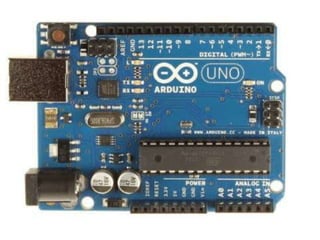
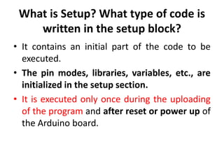
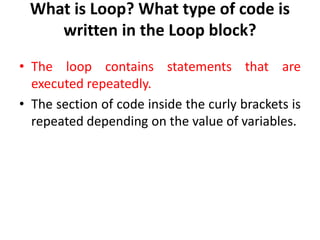
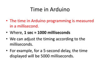
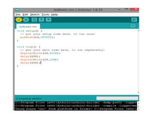
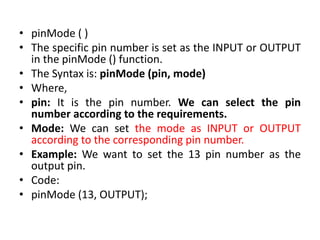
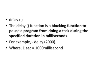
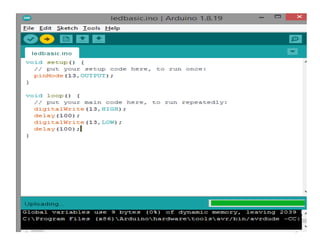
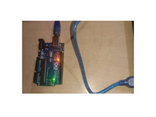
The document discusses the Arduino UNO board. It describes the components of the board including the ATmega328 microcontroller and digital and analog pins. It explains how to program the board using the Arduino IDE and connect it to a computer via USB. The steps to get started with the board are outlined, including installing drivers and uploading code to control digital pins using functions like pinMode(), digitalWrite(), and delay().
Introduction to Arduino, presented by Sana Mateen.
The Arduino UNO is an easy-to-use standard board based on the ATmega328P microcontroller, with digital and analog I/O pins.
Arduino IDE (Integrated Development Environment) allows programming Arduino boards offline and online. USB connection is crucial for programming.
Detailed components of Arduino UNO: ATmega328 Microcontroller, ICSP pin, Digital I/O pins, TX and RX LEDs, various voltage related pins, and connectors.
Arduino IDE (Integrated Development Environment) allows programming Arduino boards offline and online. USB connection is crucial for programming.
Steps to install drivers, connect Arduino to the computer, and upload sketches using the Arduino IDE.
The Setup block initializes variables and runs once, while the Loop block executes code repeatedly based on variable values.
Time in Arduino programming is measured in milliseconds. For instance, a 5-second delay translates to 5000 milliseconds.
Functions pinMode() sets pin INPUT/OUTPUT, and digitalWrite() to set pin HIGH/LOW with examples. digitalRead() reads pin value.
The delay() function pauses execution for a specified duration in milliseconds, for example, delay(2000) equates to 2 seconds.
Arduino UNO
• TheArduino UNO is a standard board of
Arduino. Here UNO means 'one' in Italian.
• Arduino UNO is based on an
ATmega328P microcontroller.
• It is easy to use compared to other boards,
such as the Arduino Mega board, etc.
• The board consists of digital and analog
Input/Output pins (I/O), shields, and other
circuits.
3.
• It isprogrammed based on IDE, which stands
for Integrated Development Environment. It
can run on both online and offline platforms.
• The IDE is common to all available boards of
Arduino.
• ATmega328 Microcontroller-It is a single chip
Microcontroller of the ATmel family. The processor
code inside it is of 8-bit. It combines Memory (SRAM,
EEPROM, and Flash), Analog to Digital Converter, SPI
serial ports, I/O lines, registers, timer, external and
internal interrupts, and oscillator.
• ICSP pin - The In-Circuit Serial Programming pin allows
the user to program using the firmware of the Arduino
board.
• Power LED Indicator- The ON status of LED shows the
power is activated. When the power is OFF, the LED will
not light up.
• Digital I/O pins- The digital pins have the value HIGH or
LOW. The pins numbered from D0 to D13 are digital
pins.
7.
• TX andRX LED's- The successful flow of data is
represented by the lighting of these LED's.
• AREF- The Analog Reference (AREF) pin is used
to feed a reference voltage to the Arduino
UNO board from the external power supply.
• Reset button- It is used to add a Reset button
to the connection.
• USB- It allows the board to connect to the
computer. It is essential for the programming
of the Arduino UNO board.
8.
• Crystal Oscillator-The Crystal oscillator has a
frequency of 16MHz, which makes the Arduino
UNO a powerful board.
• Voltage Regulator- The voltage regulator
converts the input voltage to 5V.
• GND- Ground pins. The ground pin acts as a pin
with zero voltage.
• Vin- It is the input voltage.
• Analog Pins- The pins numbered from A0 to A5
are analog pins. The function of Analog pins is to
read the analog sensor used in the connection. It
can also act as GPIO (General Purpose Input
Output) pins.
9.
• We canprogram the Arduino UNO using the
Arduino IDE. The Arduino IDE is the Integral
Development program, which is common to all
the boards.
• We can also use Arduino Web Editor, which
allows us to upload sketches and write the code
from our web browser (Google Chrome
recommended) to any Arduino Board. It is an
online platform.
• The USB connection is essential to connect the
computer with the board. After the connection,
the PWR pins will light in green. It is a green
power LED.
10.
Steps
• The stepsto get started with Arduino UNO are
listed below:
• Install the drivers of the board.
• As soon we connect the board to the
computer, Windows from XP to 10 will
automatically install the board drivers.
• But, if you have expanded or downloaded the
zip package, follow the below steps:
11.
• Click onStart -> Control Panel -> System and Security.
• Click on System -> Device Manager -> Ports (COM &LPT) -
> Arduino UNO (COMxx). If the COM &LPT is absent,
look Other Devices -> Unknown Device.
• Right-click to Arduino UNO (COmxx) -> Update Driver
Software -> Browse my computer for driver software.
• Select the file "inf" to navigate else, select
"ArduinoUNO.inf" .
• Installation Finished.
• Open the code or sketch written in the Arduino software.
• Select the type of board.
Click on 'Tools' and select Board, as shown below:
12.
Select the port.Click on the Tools -> Port (select the port). The port likely will
be COM3 or higher. For example, COM6, etc. The COM1 and COM2 ports will not
appear, because these two ports are reserved for the hardware serial ports.
Now, upload and run the written code or sketch.
To upload and run, click on the button present on the top panel of the Arduino display,
as shown below:
Within the few seconds after the compile and run of code or sketch, the RX and TX
light present on the Arduino board will flash.
The 'Done Uploading' message will appear after the code is successfully uploaded.
The message will be visible in the status bar.
14.
What is Setup?What type of code is
written in the setup block?
• It contains an initial part of the code to be
executed.
• The pin modes, libraries, variables, etc., are
initialized in the setup section.
• It is executed only once during the uploading
of the program and after reset or power up of
the Arduino board.
15.
What is Loop?What type of code is
written in the Loop block?
• The loop contains statements that are
executed repeatedly.
• The section of code inside the curly brackets is
repeated depending on the value of variables.
16.
Time in Arduino
•The time in Arduino programming is measured
in a millisecond.
• Where, 1 sec = 1000 milliseconds
• We can adjust the timing according to the
milliseconds.
• For example, for a 5-second delay, the time
displayed will be 5000 milliseconds.
19.
• pinMode ()
• The specific pin number is set as the INPUT or OUTPUT
in the pinMode () function.
• The Syntax is: pinMode (pin, mode)
• Where,
• pin: It is the pin number. We can select the pin
number according to the requirements.
• Mode: We can set the mode as INPUT or OUTPUT
according to the corresponding pin number.
• Example: We want to set the 13 pin number as the
output pin.
• Code:
• pinMode (13, OUTPUT);
20.
• digitalWrite( )
•The digitalWrite ( ) function is used to set the value of a
pin as HIGH or LOW.
• Where,
• HIGH: It sets the value of the voltage. For the 5V board,
it will set the value of 5V, while for 3.3V, it will set the
value of 3.3V.
• LOW: It sets the value = 0 (GND).
• If we do not set the pinMode as OUTPUT, the LED
may light dim.
• The syntax is: digitalWrite( pin, value HIGH/LOW)
• pin: We can specify the pin number or the declared
variable.
21.
• Let's understandwith an example.
• Example:
• digitalWrite (13, HIGH);
• digitalWrite (13, LOW);
• The HIGH will ON the LED and LOW will OFF
the LED connected to pin number 13.
22.
• What isthe difference between digitalRead ()
and digitalWrite ()?
• The digitalRead () function will read the
HIGH/LOW value from the digital pin, and the
digitalWrite () function is used to set the
HIGH/LOW value of the digital pin.
23.
• delay ()
• The delay () function is a blocking function to
pause a program from doing a task during the
specified duration in milliseconds.
• For example, - delay (2000)
• Where, 1 sec = 1000millisecond