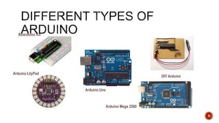
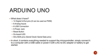
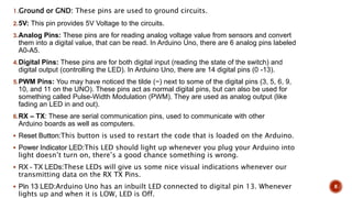
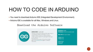
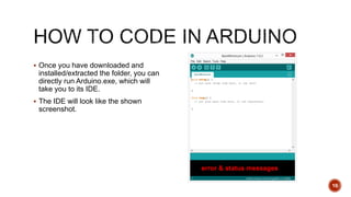
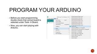
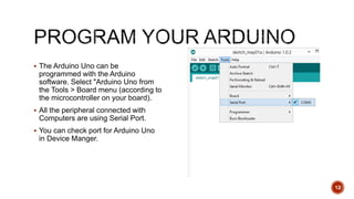
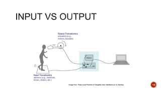
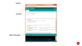
IOT :INTERNET OF THINGS
 INTRODUCTION
 DIFFERENT TYPES
 ARDUINO UNO
 HOW IT WORKS
2
 Arduino is the go-to gear for artists, hobbyists, students, and anyone with a gadgetry
dream.
 Arduino rose out of another formidable challenge: how to teach students to create
electronics, fast.
 With Arduino, you can control almost everything around you be it simple LED or giant
Robots.
3
 Basically Arduino is Microcontroller.
 Microcontroller is microprocessor with memory, RAM and some other peripheral
connected with it.
 The Arduino Uno is a microcontroller board based on the ATmega328 .
The ATmega328 has Flash memory of 32 KB (with 0.5 KB used for the bootloader). It
also has 2 KB of SRAM and 1 KB of EEPROM
4
5
Arduino Mega 2560
Arduino LilyPad
Arduino Uno
DIY Arduino
Boarduino Kit
 What does it have?
 14 Digital In/Out pins (6 can be used as PWM)
 6 Analog Inputs
 A USB Connection
 A Power Jack
 Reset Button
 On-board LED
 SCL/SDA pins (Serial Clock/ Serial Data pins)
 In short, it contains everything needed to support the microcontroller; simply connect it
to a computer with a USB cable or power it with a AC-to-DC adapter or battery to get
started.
6
Pune Makers ( http://www.meetup.com/Pune-Makers/ ) 7
1.Ground or GND: These pins are used to ground circuits.
2.5V: This pin provides 5V Voltage to the circuits.
3.Analog Pins: These pins are for reading analog voltage value from sensors and convert
them into a digital value, that can be read. In Arduino Uno, there are 6 analog pins labeled
A0-A5.
4.Digital Pins: These pins are for both digital input (reading the state of the switch) and
digital output (controlling the LED). In Arduino Uno, there are 14 digital pins (0 -13).
5.PWM Pins: You may have noticed the tilde (~) next to some of the digital pins (3, 5, 6, 9,
10, and 11 on the UNO). These pins act as normal digital pins, but can also be used for
something called Pulse-Width Modulation (PWM). They are used as analog output (like
fading an LED in and out).
6.RX – TX: These are serial communication pins, used to communicate with other
Arduino boards as well as computers.
 Reset Button:This button is used to restart the code that is loaded on the Arduino.
 Power Indicator LED:This LED should light up whenever you plug your Arduino into
light doesn’t turn on, there’s a good chance something is wrong.
 RX – TX LEDs:These LEDs will give us some nice visual indications whenever our
transmitting data on the RX TX Pins.
 Pin 13 LED:Arduino Uno has an inbuilt LED connected to digital pin 13. Whenever
lights up and when it is LOW, LED is Off.
8
 You need to download Arduino IDE (Integrated Development Environment).
 Arduino IDE is available for all Mac, Windows.and Linux.
9
 Once you have downloaded and
installed/extracted the folder, you can
directly run Arduino.exe, which will
take you to its IDE.
 The IDE will look like the shown
screenshot.
10
error & status messages
 Before you start programming,
double check that correct board is
selected under Tools  Board.
 Now, you can start playing with
Arduino.
11
 The Arduino Uno can be
programmed with the Arduino
software. Select "Arduino Uno from
the Tools > Board menu (according to
the microcontroller on your board).
 All the peripheral connected with
Computers are using Serial Port.
 You can check port for Arduino Uno
in Device Manger.
12
13
Image from Theory and Practice of Tangible User Interfaces at UC Berkley
14
 digitalWrite()
 analogWrite()
 digitalRead()
 If (statements) / Boolean
 analogRead
 Serial Communication
Microcontrollers are digital devices – ON or OFF. Also called – discrete.
Analog signals are anything that can be a full range of values.
15
5 V
0 V
5 V
0 V
Analog Sensors
16
Sensors Variables
Mic soundVolume
Photoresistor lightLevel
Potentiometer dialPosition
Temp Sensor temperature
Flex Sensor bend
Accelerometer tilt/acceleration
Digital Sensors
•Digital sensors are more
straight forward than Analog.
•No matter what the sensor
there are only two settings: On
and Off
•Example, Push button, Switch
 “Serial” because data is broken into bits, each sent one after another in a single wire.
 Compiling turns your program into binary data (ones and zeros)
 Uploading sends the bits through USB cable to the Arduino
 The two LEDs near the USB connector blink when data is transmitted.
 RX blinks when the Arduino is receiving data.
 TX blinks when the Arduino is transmitting data
17
18
Compile
Upload
Status Message
Bhoomika p
R22ES006

arduino uno

  • 1.
  • 2.
     INTRODUCTION  DIFFERENTTYPES  ARDUINO UNO  HOW IT WORKS 2
  • 3.
     Arduino isthe go-to gear for artists, hobbyists, students, and anyone with a gadgetry dream.  Arduino rose out of another formidable challenge: how to teach students to create electronics, fast.  With Arduino, you can control almost everything around you be it simple LED or giant Robots. 3
  • 4.
     Basically Arduinois Microcontroller.  Microcontroller is microprocessor with memory, RAM and some other peripheral connected with it.  The Arduino Uno is a microcontroller board based on the ATmega328 . The ATmega328 has Flash memory of 32 KB (with 0.5 KB used for the bootloader). It also has 2 KB of SRAM and 1 KB of EEPROM 4
  • 5.
    5 Arduino Mega 2560 ArduinoLilyPad Arduino Uno DIY Arduino Boarduino Kit
  • 6.
     What doesit have?  14 Digital In/Out pins (6 can be used as PWM)  6 Analog Inputs  A USB Connection  A Power Jack  Reset Button  On-board LED  SCL/SDA pins (Serial Clock/ Serial Data pins)  In short, it contains everything needed to support the microcontroller; simply connect it to a computer with a USB cable or power it with a AC-to-DC adapter or battery to get started. 6
  • 7.
    Pune Makers (http://www.meetup.com/Pune-Makers/ ) 7
  • 8.
    1.Ground or GND:These pins are used to ground circuits. 2.5V: This pin provides 5V Voltage to the circuits. 3.Analog Pins: These pins are for reading analog voltage value from sensors and convert them into a digital value, that can be read. In Arduino Uno, there are 6 analog pins labeled A0-A5. 4.Digital Pins: These pins are for both digital input (reading the state of the switch) and digital output (controlling the LED). In Arduino Uno, there are 14 digital pins (0 -13). 5.PWM Pins: You may have noticed the tilde (~) next to some of the digital pins (3, 5, 6, 9, 10, and 11 on the UNO). These pins act as normal digital pins, but can also be used for something called Pulse-Width Modulation (PWM). They are used as analog output (like fading an LED in and out). 6.RX – TX: These are serial communication pins, used to communicate with other Arduino boards as well as computers.  Reset Button:This button is used to restart the code that is loaded on the Arduino.  Power Indicator LED:This LED should light up whenever you plug your Arduino into light doesn’t turn on, there’s a good chance something is wrong.  RX – TX LEDs:These LEDs will give us some nice visual indications whenever our transmitting data on the RX TX Pins.  Pin 13 LED:Arduino Uno has an inbuilt LED connected to digital pin 13. Whenever lights up and when it is LOW, LED is Off. 8
  • 9.
     You needto download Arduino IDE (Integrated Development Environment).  Arduino IDE is available for all Mac, Windows.and Linux. 9
  • 10.
     Once youhave downloaded and installed/extracted the folder, you can directly run Arduino.exe, which will take you to its IDE.  The IDE will look like the shown screenshot. 10 error & status messages
  • 11.
     Before youstart programming, double check that correct board is selected under Tools  Board.  Now, you can start playing with Arduino. 11
  • 12.
     The ArduinoUno can be programmed with the Arduino software. Select "Arduino Uno from the Tools > Board menu (according to the microcontroller on your board).  All the peripheral connected with Computers are using Serial Port.  You can check port for Arduino Uno in Device Manger. 12
  • 13.
    13 Image from Theoryand Practice of Tangible User Interfaces at UC Berkley
  • 14.
    14  digitalWrite()  analogWrite() digitalRead()  If (statements) / Boolean  analogRead  Serial Communication
  • 15.
    Microcontrollers are digitaldevices – ON or OFF. Also called – discrete. Analog signals are anything that can be a full range of values. 15 5 V 0 V 5 V 0 V
  • 16.
    Analog Sensors 16 Sensors Variables MicsoundVolume Photoresistor lightLevel Potentiometer dialPosition Temp Sensor temperature Flex Sensor bend Accelerometer tilt/acceleration Digital Sensors •Digital sensors are more straight forward than Analog. •No matter what the sensor there are only two settings: On and Off •Example, Push button, Switch
  • 17.
     “Serial” becausedata is broken into bits, each sent one after another in a single wire.  Compiling turns your program into binary data (ones and zeros)  Uploading sends the bits through USB cable to the Arduino  The two LEDs near the USB connector blink when data is transmitted.  RX blinks when the Arduino is receiving data.  TX blinks when the Arduino is transmitting data 17
  • 18.
  • 19.

Editor's Notes

  • #5 Flash- Where program is stored. SRAM-Static Random Access Memory ( sketch creates and manipulates variables when it runs ) EEPROM- Electrically Erasable Programmable Read-Only Memory ( memory whose values are kept when the board is turned off )